Load Balancing-Failover Methods using Static
Route with Address List, ECMP, PCC, and Nth for
Optimizing LAN Network: A Comparison
Febrian Wahyu Christanto
1, Susanto
2and Agus Priyanto
31,2 Universitas Semarang, Department of Information Technology, Semarang, Indonesia 3 SMK Negeri 2 Semarang, Department of Information Technology, Semarang, Indonesia
Abstract: Internet network is a means of infrastructure to support the learning and working process. Some internet network problems that often occur are internet connection is lost, the connection is slow, and the output does not match the bandwidth that is owned. This can be accommodated by using 2 (two) internet modem units from different ISP combined with the Load Balancing process. Load Balancing used to combine two internet modems so that one connection can become a backup connection if the main connection is lost. Nowadays Load Balancing has 4 (four) methods, they are Static Router with Address List, ECMP, PCC, and Nth. The problem is choosing the best method for Load Balancing. This research uses the PPDIOO network development method. From the results of tests conducted in this research indicate the balance of internet access and bandwidth performance owned by ISP1 and ISP2 after the Load Balancing process is carried out. From testing 4 (four) Load Balancing methods, the results show that the Nth method produces 79.2% bandwidth by testing for 40 (forty) days. The conclusion is that the Nth method is more effective to be applied on a LAN network compared to other Load Balancing methods because it can divide the internet connection path when browsing, downloading, and can do a failover. Expectations going forward after applying Load Balancing Nth method can improve internet performance that is used every day for learning and working activities in an organization.
Keywords: Load Balancing, Failover, Static Route with Address List, ECMP, PCC, Nth.
1.
Introduction
Physical Network Topology emphasizes hardware related to systems including workstations, terminals, servers, and cables. Physical topology determines how the system is physically connected to a computer network device through the actual cable for data transmission [1].
MikroTik uses Linux is an operating system that is used as a network router to provide administrative settings that can be accessed using a Windows Application called WinBox. The advantage of this configuration is the computer that will be used as a Router does not require high specifications [2]. Failover is a resource that allows system administrators to automatically transfer data handling to the backup system in case of problems with the main system. Automatic failover is the best technique for computer networks with internet access when damaged or lost connectivity due to various factors, such as storms and natural disasters. In some organizations, automated Failover systems are used to
protect potential data loss in situations such as disasters or emergencies. Automatic failover allows direct handling without making settings on the server and ensures internet access goes well through the backup system if the main system is attacked by a storm or other disaster [3].
Internet network infrastructure in SMK Negeri 2 Semarang (a school in Indonesia) is quite large and extensive. Internet access including all office spaces, computer laboratories, and WiFi HotSpot throughout schools must get full internet access services so that all academicians feel they can learn and work well while at school. SMK Negeri 2 Semarang has 2 (two) internet modem units, namely the first modem from ISP Indihome with a bandwidth speed of 100 Mbps and the second modem from ISP Astinet with a bandwidth speed of 20 Mbps. The internet modem is expected to provide good and stable performance to produce optimal bandwidth for daily internet access needs at school.
Problems that occur in internet connections at SMK Negeri 2 Semarang, such as the occurrence of slow connections (down connection) and lost connections (loss connection) in one of the ISP connection lines caused by several factors, namely disconnection of FO (Fiber Optic) cables, interference or maintenance from ISP service centers, internet network traffic congestion, and small problems that arise around the school. This can disrupt the learn and work activities of internet users at SMK Negeri 2 Semarang.
and apply the best method in accordance with the characteristics of the LAN network.
2.
Network Development Method
This research uses PPDIOO methods, such as Prepare, Plan, Design, Implement, Operate, and Optimize. This PPDIOO method cycle defines approaches that can be followed for each phase of development of the Cisco version of the network life cycle. As in Figure 1 which consists of 6 (six) phases as follows.
Figure 1. PPDIOO Method [6]
Figure 1 above is the sequence of the Prepare, Plan, Design, Implement, Operate, and Optimize (PPDIOO) method. This is because the PPDIOO method is more effective for network development than the NDLC method which is more used in business in developing networks. The following is an explanation related to each stage of the PPDIOO method as follows:
Prepare: Analyzing existing problems, such as how to optimize LAN network performance by applying Load Balancing - Failover techniques from several methods using the MikroTik RB750 Router that can provide smooth and optimal internet networks, namely searching for materials, guides, references, practice materials, video tutorials , and scheduling so that the implementation phase can run well according to the initial plan.
Planning: Plan and prepare equipment such as the MikroTik RB750 Router to implement Load Balancing-Failover techniques, switches used as terminators on client PCs, Belden Cat 5e cable as a link between PCs and network devices, RJ-45 connectors are used as connectors at the end of the UTP network cable ( Unshielded Twisted-Pair) to connect the network device port to the PC, and the PC administrator used to manage and configure the Router. Design: Making a network topology design in this study with 2 (two) internet modems and 1 (one) MikroTik RB750 Router which will be configured with Load Balancing - Failover techniques. Network topology design using Microsoft Visio 2013.
Implement: Apply everything that has been planned, cover the installation and configuration of Load Balancing - Failover on the MikroTik RB750 Router to connect to the internet.
Operate: Test the Load Balancing-Failover method by disconnecting one of the ISP connections and monitoring the gateway traffic by downloading using the client computer.
Optimize: Use the most effective Load Balancing-Failover method and do maintenance if new problems occur on the network.
3.
Load Balancing
Load Balancing distributes IP traffic to multiple copies of TCP / IP network services. Each of them runs on a host on a server cluster. Partitions from client requests are allowed through hosts and clients to access clusters using 1 (one) or more virtual IP addresses. From the client's point of view, the cluster is like a server that responds to requests. If network traffic increases, the network administrator only connects other servers to the cluster [7]. Load Balancing Topology is in Figure 2
Figure 2. Load Balancing Network Topology [8]. Figure 2 above is the Load Balancing network topology consisting of 2 (two) connection links, the main link and the backup link merged into one with the Router. So if the main link arises, the backup link will automatically be activated. 3.1Static Route with Address List
Static Route with Address List is Load Balancing which classifies an IP Address range so that it can pass through one of the gateways by using static routing. This method is often used in internet cafes in order to distinguish between PC for browsing and PCs for online games. Mikrotik will determine the gateway path used by distinguishing src-addresses in data packets [9].
3.2Equal Cost Multi Path (ECMP)
Equal Cost Multi-Path (ECMP) is the selection of alternating exit routes at the gateway.
Both packets will pass through both gateways with the same load (equal cost) on each gateway. The value of the equal cost can also be defined as asymmetrically or unbalanced during routing. This is because the two ISP have vastly different speeds or bandwidths [9]. In Figure 3 is the flow of ECMP.
Figure 3 above is a client computer connected to the internet with the ECMP method of Load Balancing system. ECMP will hashing and will select the gateway ISP 1 or gateway 2 when one of the internet lines are down. ECMP will back up the connections of the two gateways combined into one. 3.3 Nth
Load Balancing Nth is a load balancing technique that forms a certain sequence which will later be used as a queuing system within the formed mangle rule. Load Balancing Nth uses the Round Robin algorithm which determines the division of connections from the mangling process to the Load Balancing route. The Nth which is implemented in a series consists of every, packet, and counter which is realized in an integer series. In this Load Balancing method, the incoming data packet will be marked as ‘n’ variable in an integer data type. With the existing rules, the path that has been marked as Nth will be combined the total bandwidth at the output which is the sum of each bandwidth on the two connections. One of the drawbacks of the Nth method is that it can break up due to gateway switching due to Load Balancing [9].
Figure 4. Nth System Flow Chart
Figure 4 is the flow of the Nth system that will process all data from the client to internet access on the Router during the mangling process based on the order of the Nth packet. The packet routing process will be routed through ISP-1 or ISP-2. Data packets from clients that enter the Router will be marked with a connection mark at the mangle stage based on the Nth order. Then each mark on the Nth packet will be given a routing mark that will determine which path to pass. During the masquerade stage, the IP address of the ISP interface used will be translated into a gateway [9].
3.4 Peer Connection Classifier (PCC)
Peer Connection Classifier (PCC) is a method that provides specifications for a packet to a specific connection gateway. PCC classifies connection traffic that will go through or out of the Router into several groups. This grouping can be
distinguished by src-address, ff-address, src-port, and dst.-port. MikroTik will determine the gateway path that was passed at the beginning of the connection traffic so that subsequent data packets that are still related to the previous data packet will be passed on the same gateway path. So that period has a disadvantage that is an overload on one of the gateways [9]. Following in Figure 5 is the flow of the PCC system.
Figure 5. PCC System Flow Chart
In Figure 5 above, it explains the workload of Load Balancing input that enters the Router through an interface that has not experienced mangle or routing processes. At this stage, the Router will read the packet header and determine the packet will be forwarded or included in the prerouting chain. The next stage of incoming connections through the ether1 interface will be marked as ISP1, while incoming connections through the ether2 interface will be marked as ISP2. Both of these interfaces lead to connections originating from the local interface to the internet to chain load balancing. Connections are marked with the results of the PCC, where the results of the hashing will be divided by 2 (two) representing the number of ISPs and the remainder of the division is used as a sign of the connections entering the Chain Load Balancing. Broadly speaking, if the remainder of the sharing result is 0 then the connection will be marked ISP1, if the remainder of the division is 1 then the connection will be marked ISP2.
4.
System Design Analysis
4.1 Hardware Requirement Analysis
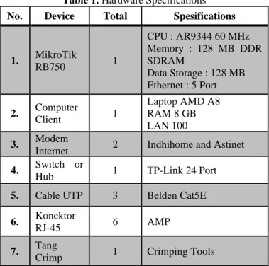
The specifications of the hardware requirements used to configure the Load Balancing-Failover of each method on the LAN network are shown in Table 1 below.
Table 1. Hardware Specifications No. Device Total Spesifications
1. MikroTik
RB750 1
CPU : AR9344 60 MHz Memory : 128 MB DDR SDRAM
Data Storage : 128 MB Ethernet : 5 Port
2. Computer
Client 1
Laptop AMD A8 RAM 8 GB LAN 100 3. Modem
Internet 2 Indhihome and Astinet 4. Switch or
Hub 1 TP-Link 24 Port
5. Cable UTP 3 Belden Cat5E
6. Konektor
RJ-45 6 AMP
7. Tang
Table 1 above is the need for network equipment used Load Balancing such as the MikroTik RB750 router used for the Load Balancing process of both internet modems, client computers are used for configuration and internet testing, switches or hubs are used to connect client computers to the MikroTik RB750 router with UTP cables.
4.2 Software Requirement Analysis
Some software that is used to support the application and testing of Load Balancing-Failover techniques are in Table 2.
Table 2. Software Specifications
No. Software Information
1. Winbox Versi.3.1 Software for remote to the MikroTik RB750 router
2. Microsoft Windows 8
As a client computer used to configure MikroTik routers and to test the internet
3.
Application Chrome, Mozilla Firefox, Internet Explorer
Browser application used to test the internet
4 Internet Download Manager (IDM)
Application used for downloading at maximum speed
Table 2 above is the application requirements for implementing Load Balancing techniques on LAN networks. 4.3 Network Topology
The initial network topology at SMK Negeri 2 Semarang is a LAN network with two internet modem units and two routers as shown in Figure 6.
Figure 6 above is an old network topology with 2 (two) internet modems and two MikroTik RB750 routers. The internet modem from the ISP Indihome is connected to the first router and the internet is distributed to the laboratory after that in each laboratory there is a MikroTik RB750 router connected to the client computer. While the internet modem from ISP Astinet is connected to the second router and the internet is distributed to the office computer.
Figure 6. Initial Network Topology
After analyzing the initial network topology, this phase also designed a new network topology following the Load Balancing topology as shown in Figure 7 below.
Figure 7. New Network Topology Design
Figure 7 is a new network topology with Load Balancing, the two internet modems that are connected to the MikroTik RB750 Router and distributed internet connections in the laboratory and office space. There are 5 (five) ports with LAN network connectors in the 5 (five) ports used namely port 1 (one) is used for internet modems from ISP Indihome, port 2 (two) is used for internet modems from ISP Astinet, port 3 (three) used for laboratory room, port 4 (four) is used for administration room, and port 5 (five) is used for teacher's room using UTP cable media.
5
Implementation Results
5.1 Network Traffic Monitoring
This test uses the Winbox Version 3.18 application on the ISP 1 and ISP 2 interface menus, so you will see network traffic that is passed from both ISP. As in Figure 8 below. 5.1.1Static Route Method with Address List
Figure 8 above shows that the Static Route method when distributing bandwidth is not balanced. Bandwidth obtained by ISP 1 reaches 50.1 Mbps while ISP 2 reaches 592 Kbps
5.1.2Equal Cost Multi-Path (ECMP) Method
Figure 9. ECMP Network Traffic Monitoring Method Figure 9 above shows that the ECMP method distributes the shared download bandwidth equally. Bandwidth obtained by ISP 1 reaches 25.2 Mbps and ISP 2 reaches 18.1 Mbps. 5.1.3Peer Connection Clasifier (PCC) Method
Figure 10 below shows that the PCC method when distributing bandwidth uses only one ISP connection and produces Bandwidth reaching 48.3 Mbps.
Figure 10. PCC Network Traffic Monitoring Method 5.1.4Nth Method
Figure 11. Nth Network Traffic Monitoring Method Figure 11 above shows that the Nth method divided into a balanced and powerful way when bandwidth distribution
process. The bandwidth obtained by ISP 1 reaches 88.7 Mbps while ISP 2 reaches 18.1 Mbps.
5.2 Download Testing
This test downloads 2 (two) videos and will know which ISP connection path will be missed.
5.2.1Static Route with Address List Method
Figure 12. Download Traffic with Static Route Figure 12 above network traffic when downloading 2 (two) videos still use ISP 2 connection lines with downloads of 4.2 Mbps, while ISP 1 is used as a backup channel.
5.2.2Equal-Cost Multi-Path (ECMP) Method
Figure 13. Download Traffic with ECMP
Figure 13 above is network traffic when downloading 2 (two) videos of the two ISP connections. This means that the Load Balancing ECMP method can divide the two ISP connection lines. ISP 1 of 2.7 Mbps and ISP 2 with downloads of 2.3 Mbps.
5.2.3 Peer Connection Classifier (PCC) Method When downloading 2 (two) videos using ISP 1 connection line with the amount of 23.6 Mbps like as in Figure 14.
5.2.4Nth Method
Figure 15. Download Traffic with Nth
Figure 15 above is the network traffic connection lines ISP 1 and ISP 2, which means the Nth method runs in a balanced manner with 92.9 Mbps and ISP 2 with 20 Mbps.
5.3Failover Testing
The failover test functions as a backup path if one ISP connection is lost. This point discuss failover test from each load balancing method.
5.3.1Static Route with Address List Failover
Figure 16. Failover with Static Router
Figure 16 is a client computer path which both requests ping google.com-t using ISP 1 and the network is lost, but client 2 (two) remains active and quickly switches lanes to ISP 2. 5.3.2Equal-Cost Multi-Path (ECMP) Failover
Figure 17. Failover with Equal-Cost Multi-Path (ECMP) Figure 17 above states that the ECMP method uses ISP 1. When ISP 1 is disconnected there is a second delay to switch to ISP 2, when ISP 1 returns, then ping to google.co.id will
return to ISP 1 with a delay of about 10 seconds to back to ISP 1.
5.3.3Peer Connection Classifier (PCC) Failover
Figure 18 below states that the PCC method uses ISP 1. When ISP 1 is disconnected, it quickly switches to ISP 2. When ISP 1 returns, ping to google.co.id will return to ISP 1 with a delay of about 10 seconds to return to the ISP 1.
Figure 18. Failover with Peer Connection Classifier (PCC) 5.3.4Nth Failover
Figure 19. Failover with Nth
Figure 19 is the Nth method that uses ISP 1. When ISP 1 is disconnected, it quickly switches to ISP 2. When ISP 1 is back, ping to google.co.id will return to ISP 1 with a delay of about 9 seconds to return to ISP 1.
5.4Public IP Addresses Detection Testing
This test is to find out the Public IP address on the client computer while browsing. This test uses an online application on the site www.whatismyaddress.com.
5.4.1Static Route with Address List
In Figure 20 above, the Static Route method can use different Public IP with 2 (two) client computers. This can distinguish the two paths that will be used.
5.4.2Equal Cost Multi-Path (ECMP)
Figure 21. Public IP with ECMP
Figure 21 shows that the ECMP method uses a different Public IP than 2 (two) client computers when browsing the internet.
5.4.3Peer Connection Clasifier (PCC)
Figure 22. Public IP with PCC
Figure 22 above shows that the Load Balancing PCC method uses the same Public IP as 2 (two) clients.
5.4.4Nth
In Figure 23 above shows that the Nth method uses the Round Robin Algorithm method which regulates the load alternately from one ISP to another.
Figure 23. Public IP with Nth
5.5Speed Test Bandwidth Graph
From previous tests, it is known the average of SpeedTest bandwidth from each Load Balancing method. The parameters tested are ping, download, and upload using an online-based application on the website www.speedtest.net. As in Figure 24 and Figure 25 below.
6 2
93.44
19.00 27.53
5.00
0 20 40 60 80 100
Internet Services Provider 1
Internet Services Provider 2
Ping (ms) Download (mbps) Uplad (mbps)
Figure 24. Before Implementing Load Balancing Graph Figure 24 above is a graph of SpeedTest bandwidth before the Load Balancing process of each internet modem. On the internet modem from ISP Indihome pinged 6 ms, downloaded 93.44 Mbps, and uploaded 27.53 Mbps, while the internet modem from ISP Astinet contained ping 2 ms, downloaded 19.00 Mbps, and uploaded 5.00 Mbps.
Figure 25. After Implementing Load Balancing Graph Figure 25 above is a graph after the Load Balancing process which is explained that load balancing is a technique of distributing the two ISP channels equally or evenly.
5.6Equations
Info : Amount of Max Bandwidth = 120 Mbps
After knowing the average of the load balancing graph above, the following is a calculation using the formula that has been explained previously as follows:
a.Static Route with Address List Method
Download 93.1 Mbps : 120 Mbps x 100 % = 77.5 % Upload 29.98 Mbps : 120 Mbps x 100 % = 23.4 % b.ECMP Method
Download 94.34 Mbps : 120 Mbps x 100 % = 78.0 % Upload 28.61 Mbps : 120 Mbps x 100 % = 24.0 % c. PCC Method
Download 93.84 Mbps : 120 Mbps x 100 % = 77.5 % Upload 28.99 Mbps : 120 Mbps x 100 % = 24.2 % d.Nth Method
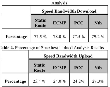
Download 95.79 Mbps : 120 Mbps x 100 % = 79.2 % Upload 32.74 Mbps : 120 Mbps x 100 % = 27.3 % The value of 120 Mbps is a combination of the two internet modems, 100 Mbps from the ISP 1 Indihome internet modem and 20 Mbps from the ISP 2 Astinet internet modem. The following is a percentage table of the results of the SpeedTest download analysis based on the above calculation contained in Table 3 and Table 4.
Table 3. Percentage Results of SpeedTest Download Analysis
Speed Bandwidth Download
Static
Route ECMP PCC Nth
Percentage 77.5 % 78.0 % 77.5 % 79.2 %
Table 4. Percentage of Speedtest Upload Analysis Results
Speed Bandwidth Upload
Static
Route ECMP PCC Nth
Percentage 23.4 % 24.0 % 24.2% 27.3%
6
Conclusions
Load Balancing Process on the MikroTik RB750 Router using the Static Route method with Address List, Equal-Cost Multi-Path (ECMP), Peer Connection Classifier (PCC), and Nth can solve the problem. If the main connection loss connection occurs then the internet connection will automatically move on the connection line that is still active. So it does not interfere with internet users in learning activities and work in an organization.
From the results of the Load Balancing test for 40 (forty) days generated data download each method, there are Static Route with Address List (77.5%), ECMP (78.0%), PCC (77.5%), and Nth (79.5%). And data upload for each method,
there are Static Route with Address List (23.4%), ECMP (24.0%), PCC (24.2%), and Nth (27.3%). So it can be concluded that Load Balancing with the Nth method is more optimal and effectively applied to LAN networks compared to other Load Balancing methods. This is because the Nth method is more powerful in bandwidth, can divide the two internet lines while browsing, downloading, and can run failover properly.
Suggestions for future research are bandwidth management on the MikroTik RB750 Router so that bandwidth can be shared evenly on active clients. And further research is needed for the application of Load Balancing for more than 2 (two) ISP connection lines.
References
[1] S. Santra and P. P. Acharjya, “A Study And Analysis on Computer Network Topology For Data Communication,” Int. J. Emerg. Technol. Adv. Eng., vol. 3, no. 1, pp. 522–525, 2013. [2] M. D. Lesmana Siahaan, “MikroTik Bandwidth Management to Gain the Users Prosperity Prevalent,” Int. J. Eng. Trends Technol., vol. 42, no. 5, pp. 218–222, 2017.
[3] R. Yusuf, “Implementation of Load Balancing and Automatic Failover for Application Internet Banking,” Int. J. Curent Res., vol. 8, no. 09, 2016.
[4] S. Discher, “Load Balancing Using PCC & RouterOS,” ISP
Supplies, 2016. [Online]. Available:
https://mum.mikrotik.com/presentations/US12/steve.pdf. [Accessed: 01-Feb-2019].
[5] R. K. Paredes, A. M. Sison, and R. P. Medina, “Bandwidth Allocation Mechanism based on Users’ Web Usage Patterns for Campus Networks,” Int. J. Commun. Networks Inf. Secur., vol. 10, no. 2, pp. 380–388, 2018.
[6] M. R. R. Fernando, L. M. N. Magaly, and C. S. M. Jose, “Analysis of Methodologies of Data Networks LAN,” Int. J. Adv. Eng. Res. Sci., vol. 3, no. 9, pp. 52–61, 2016.
[7] J. P. Duque, D. D. Beltrán, and G. P. Leguizamón, “OpenDaylight vs. Floodlight: Comparative Analysis of a Load Balancing Algorithm for Software Defined Networking,” Int. J. Commun. Networks Inf. Secur., vol. 10, no. 2, pp. 348– 357, 2018.
[8] T. Kirnak, “Bandwidth-based Load-Balancing With Failover. The Easy Way.,” Atris, 2012. [Online]. Available: https://mum.mikrotik.com/presentations/US12/tomas.pdf. [Accessed: 20-Jan-2019].
[9] E. R. Gene, “Implementasi Load Balancing Dengan Dua ISP Menggunakan Metode Nth (Koneksi Ke-N) Dan Per Connection Classifier (Pcc) Pada Mikrotik,” Sanata Dharma University, 2018.
[10] V. A. Armansyah, “Rumus Persentase,” rumus.co.id, 2019. [Online]. Available: https://rumus.co.id/rumus-persentase/. [Accessed: 01-Jul-2019].
Load Balancing Result
![Figure 2. Load Balancing Network Topology [8].](https://thumb-us.123doks.com/thumbv2/123dok_us/8121918.2154167/2.892.487.805.820.1128/figure-load-balancing-network-topology.webp)