International Journal of Communication Networks and Information Security (IJCNIS) Vol. 12, No. 2, August 2020
Performance Comparison of New Designs of Chien
Search and Syndrome Blocks for Bch and Reed
Solomon Codes
Mohamed Elghayyaty
1, Omar Mouhib
1, Azeddine Wahbi
2, Ahmed Amine Barakate
1, Anas El Habti El Idrissi
1,
Laamari Hlou
1and Abdelkader Hadjoudja
11Laboratory of Electrical Engineering and Energy System, Faculty of Sciences, University Ibn Tofail, Kenitra, Morocco 2Laboratory of Industrial Engineering, data processing and logistic, Faculty of sciences Ain Chock, University Hassan II, Casablanca,
Morocco
Abstract: Error correcting codes constitute one of the core technologies in telecommunications field, especially digital communication applications. The objective of this paper is to compare performance among new designs of chien search block on the one hand and syndrome architectures on the other hand in error correcting codes. All comparison of all designs is made by computing the number of logic, bit error rate values and number of iteration in the case of syndrome architectures
Analysis results show that the performances of the new designs based on both second factorization method and Three-Parallel Syndrome architecture are superior to the performances of traditional designs.
Keywords: Error Correcting Codes, Error Locator Polynomial, Chien Search Block, Syndrome Computation Block, Bit Error Rate (BER).
1.
Introduction
The quality of a digital transmission depends mainly on the quantity of errors introduced into the transmission channel [1] [2]. Error checking by coding is therefore essential. The use of digital signal processing techniques, and in particular the coding of the information to be transmitted, allows the detection and correction of transmission errors [3] [4]. As these techniques make it possible to control the errors induced by the noise of the transmission channel, they are called "channel coding". Among the main techniques used, block coding and convolution coding are predominant. Blocks coding are used in particular in Ethernet networks, in wireless transmission standards such as Bluetooth, and in HDTV (High Definition Television) and DVB-C (Digital Video Broadcasting-Cable) transmission standards. Convolution coding is very common in digital wireless communication systems [5] [6] [7] and other codes like RS (Reed-Solomon), and BCH (Bose, Ray-Chaudhuri) [8]. The Reed Solomon codes are block and not binary codes where the message is divided into blocks to which is added redundant information. The length of the blocks depends on the capacity of this code. For each block on the addition of protection bits or of the additional parity for the old code, a word of n symbols. It is also a systematic code, i.e. the control symbols are added at the end of the information. The coder takes K data symbols and calculates the control information to construct n symbols, which gives n-k control symbols. The decoder can correct at most t symbols, or 2t = n-k. There are more efficient codes for detecting and correcting errors, for example, the RS code (255,233.33) which is used by NASA in space communications and also in a digital terrestrial transmission chain (DVB-T).
The BCH codes (Bose, Ray-Chaudhuri, Hocquenghem), were invented in the 1960, they are cyclic codes and today they are used as a reference for many recent error correction codes. . These are relatively efficient codes, simple to implement and for which there is a set of low complexity algebraic decoding algorithms. The encoder / decoder assembly makes it possible to construct a cyclic code and to correct a number of t errors in a block of n coded symbols transmitted. Understanding the concepts of algebra in the Galois Field (GF) is necessary to better understand these codes. The block length of the BCH code built on GF (2m) is
given by n = 2m – 1. Their uses are in particular in
communications by satellite DVB-S2, compact discs CD and DVD.
A number of methods have been proposed to enhance the performance of the chien search block and syndrome architecture [9] [10] [11] [12] [13].
The goal of this work is to present a comparison analysis of the new chien search and new syndrome block with others designs in order to enhance these performances [14] [15] [16] [17].
Finally, the obtained results indicate the proposed designs as having high performance. All designs are evaluated in terms of BER, number of iterations and logic gate resources [18]. The rest of the paper is organized as follows: The Proposed robust factorization methods for RS and BCH decoder are presented in section 2. The syndromes architecture is presented in the session 3, Performance Analysis of the designed circuits are presented in section 3, followed by a conclusion.
2.
Proposed Robust Factorization Methods for
RS and BCH Decoder
The proposed algorithm is based on a specific and methodic factorization of the error locator polynomial such as {(P (x) = Axn + B, where n = 1)} should be depicted in this
polynomial. This method allows us to conceive a new circuit of Chien Search Block i.e. we can minimize both the number of components and the response time compared to the basic Chien search block.
2.1 Design using the First factorization method
If we take the case of RS (15, 11, t) the error locator polynomial is:
Λ(x) =14X2+14X+1 (1)
It’s a polynomial of degree 2 as type:
The equation (2) can be written as form: Λ (x) = (αX+β) (αX+γ)= α2X2 +αXγ+ αXβ+βγ
= α2X2+α(γ+β)X+βγ (3)
Or A2 = α2 ,A1 = α(γ+β) and A0=βγ
For equation (2) the basic circuit corresponding is represented in Figure 1.
Figure 1. Basic schema of Chien Search.
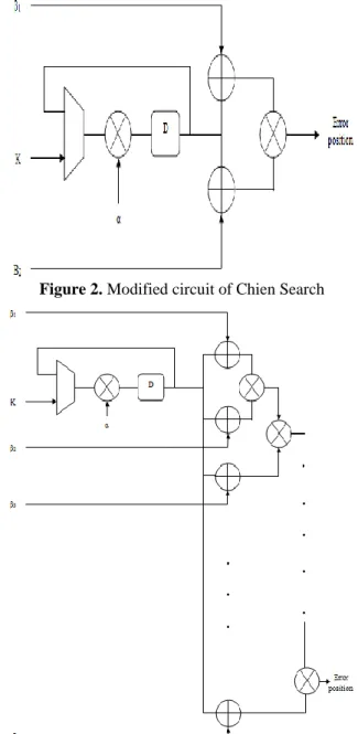
For the equation (3) the modified circuit by using the factorization method is represented in Figure 2.
Figure 2. Modified circuit of Chien Search
Figure 3. Modified circuit of Chien Search
For the case of a polynomial of degree 3 we have: Λ (X) = (αX+β) (αX+γ) (αX+λ)
= (α2X2 + α (γ + β) X + β.γ) (α X+ λ) (4)
Generally for:
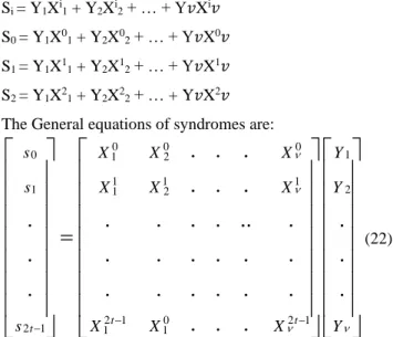
Λ (X) = (αX+β) (αX+ γ) … (αX+ν) (5) The corresponding logic circuit is represented in Figure 3.
2.2 Design using the second factorization method
• Case for odd polynomial
If we take the polynomial of degree 3 we have:
Λ(X) =AX3+BX2+ CX+D= X2(Ax + B) + (Cx + D) (6)
If we take the polynomial of degree5 we have: Λ(X) = AX5+BX4+ CX3+D X2+EX+F
= X4(Ax + B) + X2 (Cx + D) + ( EX+F) (7)
If we take the polynomial of degree7 we have: Λ(X) =AX7+BX6+ CX5+D X4+EX3+F X2+GX+H
= X6(Ax + B) + X4 (Cx + D)
+ X2(EX+F)+ (GX+H) (8)
If we take the polynomial of degree 9 we have:
Λ(X) =AX9+BX8+ CX7+D X6+EX5+F X4+GX3+H X2+IX+J
= X8(AX + B) +X6 (CX + D) + X4(EX+F)
+X2( GX+H)+( IX+J) (9)
If we take the polynomial of degree n we have:
Λ(X) = AnXn+ An-1Xn-1 +…+A1X1+A0 (10) (10)
• Case for even polynomial
If we take the polynomial of degree 4we have: Λ(X) = AX4+BX3+CX2+DX+E
=X3(AX+B)+X(CX+D)+E (11)
If we take the polynomial of degree 6 we have:
Λ(X) = AX6+BX5+CX4+DX3+EX2+FX+G= X5(AX+B) +X3
(CX+D) + X (EX + F)+G (12) If we take the polynomial of degree 8 we have:
Λ(X) = AX8+BX7+CX6+DX5+EX4+FX3+GX2+HX+I
= X7(AX+B)+X5 (CX+D) (13)
+X3 (EX + F)+X (GX + H) + I
If we take the polynomial of degree 10 we have: Λ(X) =
AX10+BX9+CX8+DX7+EX6+FX5+GX4+HX3+IX2+JX+K
= X9(AX+B) +X7 (CX+D)+X5 (EX + F)+X3(GX+H)
+X(IX+J) + K (14) If we take the polynomial of degree n we have:
Λ(X) = AnXn+ An-1Xn-1 +…+A1X1+A0 (15)
International Journal of Communication Networks and Information Security (IJCNIS) Vol. 12, No. 2, August 2020
Figure 5. Modified circuit 2 of Chien Search Block polynomial as degree 6
3.
Syndromes Architecture
The calculation of the syndrome is defined as the remainder of the division between the received polynomial R(x) and the generator polynomial g (x). The rest indicated the presence of errors. As the division operation is always a complex operation in relation to sums and additions, we are led to look for another method for calculating the syndrome. The calculation of the syndrome can also be carried out by an iterative process as illustrated in Figure 6. Before being able to calculate the polynomial of the syndrome, we must wait until we have received all the elements of the polynomial R (x).
Figure 6. syndrome calculator cell Given the binary codeword polynomial:
C(𝑥) = C0+C1𝑥+⋯+C𝑛−1𝑥𝑛−1 (16)
The received polynomial R (𝑥) =R0+R1𝑥+⋯+R𝑛−1𝑥𝑛−1 is the
sum of C (𝑥) and E( 𝑥)
R (x) = C (x) + E( x) (17)
Where:
E (𝑥) = E0+ E1𝑥+⋯+E𝑛−1𝑥𝑛−1 (18)
We obtain:
S i = R (αi) = C (αi) + E (αi ) = E (αi ) (19)
Or:
M(x).Xn-k = g(x).q(x) +X(x) (20)
M(x).Xn-k + X(x) = g(x).q(x) => C(x) = g (αi).q (αi) = 0
Then:
Si = R (αi) = E(αi) = Y1αie1+ Y2 αie2 + … + Y𝑣 αi e𝑣
= Y1Xi1 + Y2Xi2 + … + Y𝑣Xi𝑣 (21)
Where X1 = αe1, X2= αe2………..X𝑣= αe𝑣
By the equation (21) we can define the different equations which link the polynomial Syndrome errors:
Si = Y1Xi1 + Y2Xi2 + … + Y𝑣Xi𝑣
S0 = Y1X01 + Y2X02 + … + Y𝑣X0𝑣
S1 = Y1X11 + Y2X12 + … + Y𝑣X1𝑣
S2 = Y1X21 + Y2X22 + … + Y𝑣X2𝑣
The General equations of syndromes are:
0 0 0
1
0 1 2
1 1 1
2
1 1 2
2 1 0 2 1
2 1 1 1
. .
.
. .
.
.
.
.
. . ..
.
.
.
.
.
. .
.
.
.
.
.
.
. .
.
.
.
. .
.
t t
t
s X X X Y
s X X X Y
s X X X Y
− −
−
=
(22)
If the received code r (x) is not affected by errors then all the coefficients of the Syndrome will be zero (r (x) = c (x)).
3.1 Methods for Calculing the syndromes
The syndrome computation block calculates all the syndromes Si (1 ≤ i ≤16) by putting the roots of generator polynomial g(x) into the received codeword polynomial R(x).
For example the code RS (15, 11): 2t=4 syndrome (S0, S1, S2,S3)
𝑆 (𝑥) = 𝑆3𝑥3 + 𝑆2𝑥2 + 𝑆1𝑥1 + 𝑆0𝑥0 (23) Direct Method:
The equation for calculing the syndrome with the direct method [19] is:
Si = R(αi) = Rn-1(αi)n-1+ Rn-2(αi)n-2+…+ R1(α1)+R0 (24)
For calculing S1 we replace x by α1 in the following
equation:
S0 = (α0)14 +2(α0)13 + 3(α0)12 + 4(α0)11 + 5(α0)10 + 11(α0)9 +
7(α0)8 +8(α0)7 + 9(α0)6 + 10(α0)5 + 11(α0)4 + 3(α0)3 + (α 0)2 +
12(α0) + 12
S0=15
S1 = (α1)14 + 2(α1)13 + 3(α1)12 + 4(α1)11 + 5(α1)10 + 11(α1)9 +
7(α1)8 +8(α1)7 + 9(α1)6 + 10(α1)5 + 11(α1)4 + 3(α1)3+ (α1)2 +
12(α1) + 12
S1 = 3
Horner Method:
The equation for calculing the syndrome with the Horner Method [20] is:
Si = (………( Rn-1αi+ Rn-2)αi+…+ R1)α1+R0 (25)
S2 = (((((((((((((1 α2 + 2).α2 + 3) α2 + 4).α2 + 5) α2 + 11).α2 +
7).α2 + 8) α2 + 9) α2 + 10).α2 + 11)
S3 = (((((((((((((1 α3 + 2).α3 + 3) α3 + 4).α3 + 5) α3 + 11).α3 +
7).α3 + 8) α3 + 9) α3 + 10).α3 + 11)
S3 = 12
𝑆 (𝑥) = 𝑆3𝑥3 + 𝑆2𝑥2 + 𝑆1𝑥1 + 𝑆0𝑥0
𝑆 (𝑥) = 12𝑥3+ 4𝑥2+ 3𝑥1+ 15𝑥0
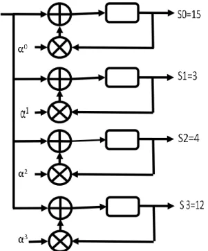
The following figure shows the principle of calculation of the four syndromes at the same time:
Figure 7. Logic circuit of the RS syndrome block (15, 11)
3.2 Serial Architecture
The serial syndrome computation block is implemented by following equation 4.
Si = R (αi) = r254(αi)254 + r253(αi)253 +……. r1(αi) + r0 (26)
Figure 8. Serial Syndrome Block Diagram
The received vector enters serially to the circuit to compute the syndrome coefficients in parallel in n or (255) clock cycles, as shown in Figure 8.
For the case of RS (255, 239,) where: N = 255, K = 239 we have N-K = t =16=> 16 Syndromes: S1, S2, …, S16.
S1 can be calculated by the direct method and the even syndromes can be calculated using the following relationship S2i = Si2.
3.3 Three-Parallel Syndrome
Three -parallel syndrome computation block [ref] can be expressed by the equation presented in equation. 4. Which equivalent to equation.4.1 but in another form.
R(x) = r254x254 + r253x253 +……. r1x + r0 (27)
G(x) = (x-α0) (x-α1) ………. (x-α14) (x-α15) (28)
Si = R(αi) = r
254(αi)254 + r253(αi)253 +……. r1(αi) + r0 (29)
Where: i = 1, 2, . . ., 2t
Figure 9. Three parallel syndrome computation block The Three parallel syndrome computation block calculated by this equation:
S i= R(αi) =
((…(r254(αi)2+r253(αi)1+r252)(αi)3+r251(αi)2+r250(αi)1+r249)
(αi)3+….)(αi) 3+r
2(αi)2+r1(αi)1+r0 ) (30)
In the first clock, the mot received is (r254, r253, r252) in parallel, the second mot r252 is going to adder, r523 is
multiplied by αi and added to r
252,the final r254 is multiplied by
(αi)2 and added to( r
253*(αi)1+r251). So the output of latch(1) is :
r254(αi)2r253*(αi)1+r251.the second clock the output of latch(1) is
multiplied by (αi)3 and then added with r
251(αi)2+ r250(αi)1+r249
4.
Performance Analysis of the Designed
Circuits
4.1 performance and Comparison of designs based factorization methods
The proposed circuits are compared in terms of BER performance and Number of iterations, and number of minimized logic gates.
Tables 1, 2 and 3, also Figure 10, 11, 12, 13, 14 and 15 show the evaluation of the performance based on the number of the used logic gates and the obtained values of bit error rate BER for all designs by using the modified circuit for different error locator polynomials, especially in the case of second factorization method both odd error locator and even error locator.
Table 1. Computational minimization rate logic gates and BER values of the design based first factorization method
Error locator polynomial
Minimization rate
BER
Λ(X) =AX2+BX+ C 45, 45 0,000054
Λ(X) =AX3+BX2+
CX+D 46,66 0,000053
Λ(X) =AX4+BX3+
CX2+DX+E
47,36 0,000052
. . .
. . .
. . . Λ(X)=AnXn+
…….+A1X+A0
2
1
.100 %
3 4
n
n
+
+
D
D
D
International Journal of Communication Networks and Information Security (IJCNIS) Vol. 12, No. 2, August 2020
Table 2. Computational minimization rate logic gates and BER values of the design based second factorization method
with odd error locator polynomial Error locator
polynomial
Minimization rate BER
Λ(X) =AX3+BX2+
CX+D
33 ,33 0.000066
Λ(X) =
AX5+BX4+CX3+DX2+
EX+F
34,78 0 .000065
Λ(X)=AX7+BX6+CX5
+DX4+EX3+FX2+GX+
H
35,48 0.000064
. . .
. . .
. . . Λ(X)=AnXn+
…….+A1X+A0
Table 3. Computational minimization rate logic gates and BER values of the design based second factorization method
with even error locator polynomial Error locator polynomial Minimization
rate
BER
Λ(X)=AX4+BX3+CX2+
DX+E 31,57 0,000068
Λ(X)=AX6+BX5+CX4+
DX3+EX2+FX+G
33, 33 0,000066 Λ(X)=AX8+BX7+CX6+
DX5+EX4+FX3+GX2+H
X+I 34 ,28 0,000065 .
. .
. . .
. . . Λ(X)=AnX+…..A1X+A0
These tables provide the necessary information about the performance of each design in terms of Number of minimized logic gates and the bit error rate (BER).
During testing from all designs, we can see that there is a significant decrease of number of minimized logic gates after enhancement is applied (for both proposed designs). Minimization rate for the second factorization method is over 34% or 35%, and for the first factorization method varies from 45% to 47,36%. Therefore, although for both presented figures 10, 11, 12, 13, 14 and 15, also table 1, 2 and 3 comparisons, we can say that both proposed designs, especially, the one based first factorization are adequate solutions for BCH and RS decoders and give slightly better results.
1 2 3
42,5 43,0 43,5 44,0 44,5 45,0 45,5 46,0 46,5 47,0
Mi
n
imi
za
ti
o
n
ra
t
(%
)
Error locator polynomial degree
Figure 10. Evolution of the minimization rate depending on the degree of the error locator polynomial for the modified
circuit based first factorization method
3 4 5 6 7
33,0 33,5 34,0 34,5 35,0 35,5
Error locator polynomial degree
Mi
n
imi
za
ti
o
n
ra
t
(%
)
Figure 11. Evolution of the minimization rate depending on the degree of the odd error locator polynomial for the
modified circuit based second factorization method
4 5 6 7 8
31,5 32,0 32,5 33,0 33,5 34,0 34,5
Error locator polynomial degree
Mi
n
imi
za
ti
o
n
ra
t
(%
)
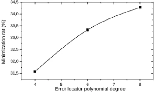
Figure 12. Evolution of the minimization rate depending on the degree of the even error locator polynomial for the
modified circuit based second factorization method
42,5 43,0 43,5 44,0 44,5 45,0 45,5 46,0 46,5 47,0 5,2x10⁻⁵
5,2x10⁻⁵
5,3x10⁻⁵
5,3x10⁻⁵
5,4x10⁻⁵
BER
Minimization rate (%)
Figure 13. Evolution of the bit error rate BER depending on the minimization rate for the modified circuit based first
33,0 33,5 34,0 34,5 35,0 35,5 6,4x10⁻⁵ 6,4x10⁻⁵ 6,5x10⁻⁵ 6,5x10⁻⁵ 6,6x10⁻⁵ BER
Minimization rate (%)
Figure 14. Evolution of the bit error rate BER depending on the minimization rate for the modified circuit based second
factorization method with odd error locator polynomial
31,5 32,0 32,5 33,0 33,5 34,0 34,5
6,5x10⁻⁵ 6,5x10⁻⁵ 6,6x10⁻⁵ 6,6x10⁻⁵ 6,7x10⁻⁵ 6,7x10⁻⁵ 6,8x10⁻⁵ BER
Minimization rate (%)
Figure 15. Evolution of the bit error rate BER depending on the minimization rate for the modified circuit based second
factorization method with even error locator polynomial
4.2 performance and Comparison of the serial and parallel Circuits for the syndrome Computation architectures
Let’s discuss now the performances of different types of Syndrome Computation Architectures by using number of iteration criteria. In this context, Table 5 shows the effect of the number of iteration to the performance of the proposed designs.
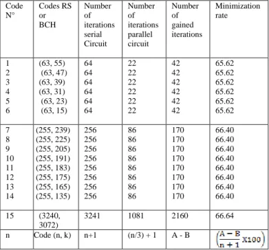
In this table 4 shows the number of the gained iterations by using the basic and the modified circuit for different RS and BCH codes.
Table 4. Computational minimization rate of logic gates and number of iterations of the serial and parallel Circuits for the
syndrome Computation block
Minimization rate Number of gained iterations Number of iterations parallel circuit Number of iterations serial Circuit Codes RS or BCH Code N° 65.62 65.62 65.62 65.62 65.62 65.62 42 42 42 42 42 42 22 22 22 22 22 22 64 64 64 64 64 64 (63, 55) (63, 47) (63, 39) (63, 31) (63, 23) (63, 15) 1 2 3 4 5 6 66.40 66.40 66.40 66.40 66.40 66.40 66.40 66.40 170 170 170 170 170 170 170 170 86 86 86 86 86 86 86 86 256 256 256 256 256 256 256 256 (255, 239) (255, 225) (255, 205) (255, 191) (255, 183) (255, 175) (255, 165) (255, 135) 7 8 9 10 11 12 13 14 66.64 2160 1081 3241 (3240, 3072) 15
A - B (n/3) + 1 n+1
Code (n, k) n
As can be seen, we use the following parameter Block Length (n) and the number of information symbols in a code word (k). Thus, from this analysis, we can see that first design based the first factored method gives the better performance than the other design in term number of gained iterations. Because, it needs ((n/3) + 1) iteration instead (n+1) for the second design, however this method gives Minimization rate between 66.40 and 65.62.
This increase in performance, as well as the increase in reliability makes it perfect for BCH and RS decoders. Here the number of iterations are taken are minimize and its summary of the performance is presented in Table 5.
Figure 16 shows the minimization rate performance of the modified Circuit for the syndrome Computation architectures. Performance analysis is carried out by varying the Block Length (n) and number of information symbols in a code word (k) and calculating the corresponding number of iteration and minimization rate percentage. The results obtained are compared to that obtained from the serial circuit.
65,6 65,8 66,0 66,2 66,4 66,6 66,8 (3240,3070) (255,239) Mi ni mi za tio n ra te (% ) code (n,k) (63,55)
Figure 16. Evolution of the minimization rate depending on the code (n, k)
5.
Conclusions
In this work, different designs were analyzed and compared .therefore, several test scenarios concerning the proposed designs have been carried out, in order to validate its effectiveness. Evaluation performances showed that it is effective when the new designs are applied.
The major advantage of the proposed design using second factorization method is its minimized number of logic gates and ease of implementation. That is can decrease the BER to optimal values.
For the second contribution, the new design based Three-Parallel Syndrome architecture shows a high performance in term number of gained iterations. It can be seen that when considering the minimized number of iterations, the Three-Parallel Syndrome architecture is the obvious choice for the real time RS and BCH decoders.
Further work could be done in optimizing designs for RS and BCH codes and developing techniques specifically designed and LPDC codes.
References
[1] Orhan Gazi, “Forward Error Correction via Channel Coding Engineering”, Springer, Cham, 2020
[2] P. Salija and B. Yamuna, “Optimum energy efficient error control techniques in wireless systems: a survey”, journal of Communications Technology and Electronics, vol. 60, pp. 1257–1263, 2015.
International Journal of Communication Networks and Information Security (IJCNIS) Vol. 12, No. 2, August 2020
[4] Robert H. Morelos, “Zaragoza, The Art of Error Correcting Coding”, John Wiley & Sons, Electronic, ISBN:9780470847824, 2002.
[5] K. Deergha Rao, “Channel Coding Techniques for Wireless Communication”s, Electronic ISBN: 978-81-322-2292-7, Springer India, 2015.
[6] Trung Q. Duong and Nguyen-Son Vo, “Wireless Communications and Networks for 5G and Beyond”, MOBILE
NETWORKS AND APPLICATIONS, VOL. 24, PP.443–446,2019.
[7] Krishnamoorthy Narasu Raghavan et al., “Performance Analysis of Convolution Code with Variable Constraint Length in Shallow Underwater Acoustic Communication”, International Journal of Computer Network and Information Security (IJCNIS), Vol.11, No.2, PP. 13-20, 2019.
[8] Rajashri Khanai et al., “Performance Analysis of Underwater Acoustic Communication using IDMA-OFDM-MIMO with Reed Solomon and Turbo Code”, International Journal of Computer Network and Information Security (IJCNIS), Vol.10, No.12, PP.41-46, 2018.
[9] Elghayyaty Mohamed et al., “Minimized Logic Gates Number Of Components In The Chien Search Block For Reed-Solomon (RS)”, American Journal of Engineering Research (AJER), Vol.7, No.2, pp. 110-116, 2018.
[10] MelikeYigit, PinarSarisarayBoluk, V. CagriGungor, “A new efficient error control algorithm for wireless sensor networks in smart grid”, Computer Standards & Interfaces, Vol. 63, pp. 27-42, 2019.
[11] Vrajkishandugar et al., “A Survey On Hamming Codes For Error Detection”, 2nd International Conference On Intelligent Computing, Instrumentation And Control Technologies (ICICICT), pp. 633-638, 2019.
[12] Jagannathsamanta et al., “FPGA Based Area Efficient RS(23, 17) Codec”, Microsystem Technologies, Vol. 23, pp. 639-650, 2017.
[13]Vicente Torres et al., “Soft-Decision Low-Complexity Chase Decoders For The Rs(255,239) Code”, Electronics, Vol. 9, No. 8, 2019.
[14] Elghayyaty Mohamed et al., “Performance Study of BCH Error Correcting Codes Using the Bit Error Rate Term BER”, Int. Journal of Engineering Research and Application, Vol. 7, No. 2, pp.52-54, 2017.
[15] V. Pushpa et al., “BER Analysis Of BPSK for Block Codes and Convolution Codes Over AWGN Channel”, International Journal Of Pure And Applied Mathematics, Vol. 114, No. 11, pp. 221-230, 2017.
[16] Alyaa Al-Barrak et al., “Enhancing BER Performance Limit of BCH and RS Codes Using Multipath Diversity”, Computers, Vol. 6, No. 21, pp. 1-13, 2017.
[17]Bashar Tahir et al., “BER Comparison Between Convolutional, Turbo, LDPC, and Polar Codes”, IEEE 24th International Conference On Telecommunications (Ict), pp. 1-7, 2017. [18] Yuval Genga et al. , “Improving the Decoding Performance of
the PTA Algorithm for RS Codes Through the Extension of the Parity Check Matrix”, IEEE Africon, pp. 171-174, 2017. [19] Richard W. Middlestead, “Digital Communications with
Emphasis On Data Modems: Theory, Analysis, Design, Simulation, Testing, And Applications”, Wiley Telecom, Electronic ISBN: 9781119011866, JOHN WILEY & SONS,
INC.,2017.