Low Complexity Reliability Based Message Passing Decoder
Architecture For Non Binary LDPC Codes
Maddirala Kranthi Kiran M.Tech Student (VLSI System Design) Srinivasa Institute of Science And Technology,
kadapa
Email-Id: [email protected]
G Venkata Karthik Assistant Professor
Srinivasa Institute of Science and Technology, kadapa
Email–Id:[email protected]
Abstract: Non-binary low-density parity-check (NB-LDPC) codes can achieve better error-correcting performance than their binary counterparts at the cost of higher decoding complexity when the codeword length is moderate. The recently developed iterative reliability-based majority-logic NB-LDPC decoding has better performance complexity tradeoffs than previous algorithms. This paper first proposes enhancement schemes to the iterative hard reliability-based majority-logic decoding (IHRB-MLGD). Compared to the IHRB algorithm, our enhanced (E)-IHRB algorithm can achieve significant coding gain with small hardware overhead. Then low-complexity partial-parallel NB-LDPC decoder architectures are developed based on these two algorithms. Moreover, novel schemes are developed to keep a small proportion of messages in order to reduce the memory requirement without causing noticeable performance loss. In addition, a shift-message structure is proposed by using memories concatenated with variable node units to enable efficient partial-parallel decoding for cyclic NB-LDPC codes. our proposed decoders have at least tens of times lower complexity with moderate coding gain loss.
Index Terms—Iterative majority-logic decoding, low-density parity-check (LDPC) codes, Tanner Graph, Algorithms, non-binary, partial-parallel, VLSI,
I. Introduction
NON-BINARY low-density parity-check (NB-LDPC) codes defined over GF (q) (q>2) can achieve higher coding gain than their binary counterparts when the code length is moderate. However, the decoding of NB-LDPC codes is much
more complicated since vectors of messages need to be computed and stored. To reduce the complexity of the belief propagation (BP) for NB-LDPC decoding, frequency-domain, log-domain and mixed-domain decoders were proposed. In addition, further complexity reductions have been made in the extended Min-sum (EMS) and Min-max algorithms through approximating the computations involved in non-binary BP. Decoder architectures based on the EMS and Min-max algorithms can be found in. It was reported that the implementation of a partial parallel Min-max decoder for a (744, 653) NB-LDPC code over GF(25) needs more than 47 000 slices on a Xilinx Virtex-IIPro FPGA device and can only achieve a throughput of 9.3 Mbps when 15 decoding iterations are carried out. On the other hand, a binary LDPC decoder for the WiMax standard needs less than 2500 slices on a device of the same family to achieve 28 Mbps.
can achieve effective complexity-performance tradeoff. Compared to the ISRB algorithm, the IHRB algorithm updates reliability messages based on the hard decisions instead of probabilities of the received symbols. Hence, at the cost of moderate coding gain loss, the IHRB algorithm has much lower computation complexity and memory requirement than the ISRB algorithm. Nevertheless, mapping the IHRB algorithm directly to hardware implementation still leads to high complexity.
This paper first proposes an enhanced (E-)IHRB algorithm. Through incorporating the probability information from the channel into the message initialization of the IHRB algorithm and excluding the contribution of the same check node from the variable-to-check (v-to-c) message, the E-IHRB algorithm can bridge the performance gap between the IHRB and ISRB algorithms with small complexity overhead. Novel partial parallel architectures are also developed in this paper to efficiently implement the IHRB and E-IHRB algorithms through algorithmic and architectural optimizations. Many construction methods of NB-LDPC codes lead to quasi-cyclic (QC) or cyclic codes For QC codes, our IHRB decoder processes one row of sub-matrices at a time, and the variable node units (VNUs) are implemented by simple logic when all ( q) messages in a vector are kept. Cyclic NB-LDPC codes have the advantage that their encoders can be implemented easily by linear feedback shift registers. However, these cyclic codes usually involve finite fields of high order, in which case keeping all q messages leads to large memory requirement. Novel schemes are developed in this paper to store only a small proportion of the messages without incurring noticeable performance loss. In addition, a shift message decoder architecture is proposed for cyclic NB-LDPC codes to enable efficient partial-parallel processing. The message shifting is accomplished through concatenating memories with VNUs to reduce the area requirement. It is non-trivial to extend the IHRB decoder architecture to implement the E-IHRB algorithm since recording the messages from check nodes may
lead to large memory overhead, especially when the column weight of the code is not small.
The structure of this paper is as follows. Section II introduces the IHRB algorithm for NB-LDPC decoding. The proposed E-IHRB algorithm is detailed in Section III. Then the IHRB and E-IHRB decoder architectures are presented in Sections IV and V, respectively. After complexity analyses and comparisons are done in Section VI, conclusions are drawn in Section VII.
II . IHRB–MLD Algorithm
An LDPC code is a linear block code that can be defined by the corresponding parity check matrix H or the associated Tanner graph. In the Tanner graph, a check (variable) node rep-resents a row (column) of H, and the ith check node is connected to the jth variable node if the
corresponding entry hi,jin H is nonzero. To simplify
notations, this paper considers regular NB-LDPC codes, whose H matrix has constant row weight dc
and constant column weight dv. To reduce the decoder hardware complexity, QC, and cyclic NB-LDPC codes can be constructed using the methods. The H - matrix of a QCNB-LDPC code can be divided into sub-matrices that are zero or shifted identity matrices with nonzero entries replaced by elements of GF(q) .For a cyclic NB-LDPC code, the H matrix consists of a single circulant matrix whose entries are elements of GF(q) or a column of circulant matrices.
Algorithm A : IHRB- MLGD Algorithm
Initialization : Rj,l(0)= r if Zj(0)= l;
Rj,l (0)
= 0 if Zj (0)
!= l for K = 0; Imax
A1:stop if Z(K) HT= 0 for i = 0 to m-1 for J€ Ni
A2 : ϭi,j = hi,j-1∑u€Ni\jZu(k)hi,u
A3 : if (ϭi,j = αl) Rj,l(k)= Rj(k)+1
for j = 0 to n-1
A4 : Zj(K+1) = field elements of maxlRj,l(k+1)
In the IHRB algorithm, the reliability measures of the received symbols are updated in each iteration based on the hard-decision symbols. Throughout this paper, the superscript (k) is added to denote the values in the kth decoding iteration whenever necessary. In addition, a vector of variables with subscripts is also represented by the same variable with deleted subscript. For a NB-LDPC code of length n , let Z(k) = [ Z0(K), Z1(K), Z2(K), …… Z
n-1(K)] be the hard decision vector of the received symbols in the Kth decoding iteration, and z(0) consists of the hard decisions made from the channel output. Rj
(K) = [ Rj,0
(k) , Rj,1
(k) , Rj,2
(k)
, ……… Rj,q-1 (k)
] is the reliability measure vector of the jth received symbol, representing the probabilities that the jth received symbol equals each field element. Assume that the H matrix has m rows. Define ,
Ni = {j: 0 , 0 <j < n,hi,j / 0}
Mj = {i: 0 , 0 <i < m, hi,j / 0}and the{ 0,
1,……….. q-1} set consists of all elements of GF(q)
.The IHRB algorithm can be described by Algorithm A
III. Enhanced IHRB–MLD Algorithm
One reason that the IHRB algorithm has performance loss compared to the ISRB algorithm is that the soft information is lost in the initialization of the reliability easures: the reliability measure for the hard-decision symbol is set to, while all other measures in the same vector are set to zero. Recording different initialization values does not cost extra memory, if the word length is not changed. Hence, the IHRB algorithm can be enhanced by initializing the reliability measures according to the probability information from the channel in a way similar to that in the ISRB algorithm. Nevertheless, to reduce the decoder hardware complexity, the maximum reliability measure in each vector should
be set to a constant r in the format of 2m–1 (w€ Z+)
as before , so that it does not need to be stored , and the Clipping can be Simplified as will be detailed.
Such initialization can be done first as Rj,l(0) = | Uj,l P |, ( 0 < l < q ) where p is a constant that similar effect as the U in the ISRB decoding. The Optimum Value of P can be derived from simulations, and is affected by the data format of reliability measures and dynamic range of the symbol reliabilities from the channel.
Algorithm B: E -IHRB- MLGD Algorithm
Initialization : Rj,l(0)= max (| |+ r–maxl( ) ) if Zj(0) = Zj(0);
for K = 0; Imax
B1:stop if Z (K)
HT= 0 for i = 0 to m-1 for J€ Ni
B2 : ϭi,j(k) = hi,j-1∑u€Ni\jZu(k)hi,u
B3 : if (ϭi,j = αl) Rj,l(k)= Rj,l(k)+1
Rj,l(k+1)= Rj,l(k)
for j = 0 to n-1
B4 : Rj (K+1)max
= maxlRj (K+1)max
Zj (K+1)max
field elements of maxl
Rj,l(k+1)max
B5 : Rj(K+1)max2 = second largest Rj(K+1)max
Zj(K+1)max= field elements of maxl
Rj,l(k+1)max2
for i
€Mj if (ϭi,j(k) = Zj(K+1) &
(Rj (K+1)max
< Rj (K+1)max2
+1)
Zi,j(K+1)= Zjr(K+1)
elseZ
IV. PARTIAL–PARALLEL ARCHITECTURES FOR IHRB-MLGD
Since the E-IHRB algorithm is based on the IHRB algorithm, this section presents architecture design for the IHRB algorithm first. Then the modifications needed to implement the E-IHRB algorithm are introduced in the next section.
Fully-parallel decoders require overwhelming complexity for NB-LDPC codes that are not very short. On the other hand, serial design cannot achieve fast decoding speed. Compared to random codes, these codes enable more efficient partial-parallel processing due to the regularity in the matrix. In this section, partial-parallel IHRB decoder architectures are developed for these two types of codes.
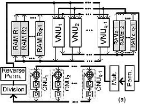
Fig : 1 IHRB-MLGD architecture for QCNB-LDPC Codes
A. IHRB-MLGD Architecture for QCNB-LDPC Codes
The H matrix of a QCNB-LDPC code consists of sub-matrices that are either zero or shifted identity matrices with nonzero entries replaced by finite field elements. In our design, one row of sub-matrices of H is processed at a time. Assume that H consists r x t of sub-matrices of dimension (q-1) x
(q-1). If none of the sub_matrices is zero , then dc= t and dv =t . The top level architecture of our proposed IHRB decoder for QCNB-LDPC codes is shown in Fig. 5(a). RAM Ri (1< i < q) stores reliability measure vectors R(q-1)b+i-1
(k)
for b = 0,1,….,t-1 ,and all the q measures in a vector are stored in the same address location. A similar scheme is used to store the hard-decision symbols in RAM z, except that each RAM z consists of two blocks: one for Z(k)and for Z(k+1). Using this storage scheme, the messages for one block column (q-1 columns) of H can be accessed simultaneously.
Fig 2 : VNU architecture when all q messages are kept.
One row of sub-matrices is processed at a time in our design, and each sub-matrix has at most one nonzero entry in each column. Hence, at most one of the measures in each Rj(k) vector can be added by one each time. The multiplexor at the output of the memory storing in Fig. 2 selects Rj,l(k) ifϭi,j = αl , and passes it to the adder to be increased by one. In our design, the clipping is done at the same time as the reliability measure updating, and can be simplified since at most one measure in each vector is increased by one at a time. If Rj,l(k) the for which is ϭi,j = αl already r before the addition by one, it should remain unchanged and each of the other nonzero reliability measures in
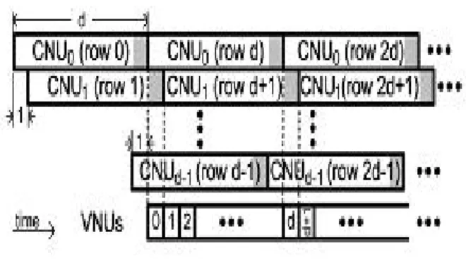
Fig 3: Computation Scheduling in IHRB–MLGD for Cyclic Codes.
the same vector is subtracted by one. The outputs of the second-row multiplexors in the top part of Fig. 2 are the updated and clipped reliability measures, except Rj,l(k) , which should come from the 2-to-1 multiplexor in the middle. To address this issue, a binary decoder is employed to convertϭi,j to a binary tuple, which is only “1” in the bit if ϭi,j = αl . This binary tuple is used as the select signals for the top-row multiplexor.
According to the initialization in Algorithm A and the clip-ping method adopted, the hard-decision symbol can be only replaced by ϭi,j when
the corresponding Rj,l(k) is already r before it is increased by one. Hence, instead of being updated at the end of each decoding iteration, which requires finding the index of the largest reliability measure in each vector, can be updated using a multiplexor as shown in Fig. 2 during the processing of each block row of .
The q-1 VNUs update the reliability measure vectors and hard-decision symbols for one block column at a time. Hence, the variable node processing (A3 and A4 steps of Algorithm A) for a block row of can be completed in clock cycles. These computations can overlap with the check node processing for the next block row. Hence, the decoding with iterations Imax takes around (1+ r Imax)t clock cycles in this IHRB decoder for QCNB-LDPC codes.
B. IHRB-MLGD Architecture for Cyclic NB-LDPC Codes
This subsection considers the decoder design for cyclic NB-LDPC codes whose matrix consists of a single circulant matrix. Using the construction methods , each row in a cyclic is cyclically shifted previous row multiplied by w , where w is a primitive element of GF(q) . However, the nonzero entries in a row appear at irregular locations. If the CNU or VNU has multiple messages to process at a time, the hardware complexity will increase significantly. Hence, the decoder architecture developed previously for QC codes can not achieve efficient partial-parallel processing for cyclic codes.
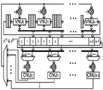
Fig 4 : IHRB–MLGD architecture for cyclic NB-LDPC Codes.
Fig. 4 shows our proposed IHRB decoder architecture for cyclic NB-LDPC codes. Assume that there are nonzero entries In the first row of the cyclic H , and they are located at positions p0p1,….Pd-1. Our
design employs d CNUs. Each CNU has the same architecture as that shown in Fig.1, and computes a check sum in d clock cycles. However CNUi, starts one clock cycle after CNUi-1 in this cyclic decoder. The hard-decision symbols Z(k) and Z(k+1) are stored in two sets of shift registers, and are cyclically shifted by one position to the left in each clock cycle. Accordingly, all CNUs can read from the same d registers of Z(k)located at positions . P0,P1-1, ……, Pd-1–(d-1). As a result, the permutation network for routing messages to CNUs is simplified. The connections illustrated in Fig. 4 is for an example code with P0,P1,P2,…..= 0,3,7……. Each multiplexor
in this figure sends one of the d hard-decision symbols to the connected CNU at a time after it is multiplied by the corresponding entry in H . The select signals of these multiplexors can be generated by counters. Similarly, the counter for the (i+1)th multiplexor lags behind that for the ith multiplexor by one clock cycle. It takes d clock cycles to compute the first check sum in CNU0 . After that, one additional check sum will be available from CNU0,
CNU1, in each clock cycle. More-over, after a CNU finished computing the check sum for row i+d , it can start the check sum . The gray areas in this figure indicate the clock cycles in which the check sums for the corresponding rows are ready.
V. PARTIAL–PARALLEL
ARCHITECTURES FOR E - IHRB -MLGD
flags f Zi,j , , are stored to denote whether or has been selected as Zi,j(k) .These flags are updated with Step B6 of Algorithm B in each iteration. To avoid finding the largest and the second largest reliability measures in each vector at the end of the decoding iteration, Zj
(k+2) , Zj
r(k+2 ) and Rj
(k+2)max2 , Rj
r(k+2)max2
are also updated with each addition to there liability measure in Step B3 of iteration K+1 , and the updated values need to be stored. Hence, the decoder needs to record the hard-decision symbols and the second most likely symbols for three consecutive iterations. On the other hand, Step B6 only requires the information if Rj(k+2)max2 > Rj(k+2)max–1 . Therefore, instead of using a second copy of memory to store Rj(k+2)max2,flags frj, are recorded to indicate whether this inequality is true. Table II summarizes the extra variables need to be stored in order to implement the enhancement in Step B5 and B6.
VI RESULTS
In the IHRB and E-IHRB decoders for the (403, 226) QCNB-LDPC code over GF(25) , all q = 32 messages are kept for each vector. In addition, r = 7 is adopted for both decoders. Nevertheless, the hard-decision symbols are stored in RAMs in QC decoders. The larger number of hard-decision symbols that need to be stored causes the memory increase in the QC E-IHRB decoder compared to that in the QC IHRB decoder. Similarly, there are more logic gates in the QC E-IHRB decoder due to the selector blocks, and modified VNUs. In total, the E-IHRB decoder requires 28% more memory and 22% more gates than the IHRB decoder for the (403, 226) QCNB-LDPC code. The area overhead for implementing the enhancement schemes for QC codes is less than that for cyclic codes. This is mainly be-cause that, in the case of QC codes, the extra hard-decision sym-bols are stored in memories, which usually cost less area than registers. To decode each received word, both the IHRB and E-IHRB decoders for the (403, 226) QC code require around (1 + 8 x 25) x 13 = 2613 clock cycles. The critical paths of both decoders have eleven gates
VII. CONCLUSION
This paper proposed enhancement schemes to the IHRB de-coding algorithm for NB-LDPC codes. The proposed schemes lead to significant coding gain with small complexity overhead. In addition, efficient architectures were developed for both QC and cyclic NB-LDPC codes based on the IHRB and E-IHRB algorithms. With moderate performance loss, the proposed de-coders can achieve at least tens of times higher efficiency com-pared to previous designs based on the Min-max algorithm. Future work will be devoted to further improving the performance and reducing the hardware complexity of MLGD-based algorithms for NB-LDPC decoding.
REFERENCES
[1] L. Barnault and D. Declercq, “Fast decoding algorithm for LDPC over,” in Proc. Inf. Theory Workshop, 2003, pp. 70–73.
[2] H. Wymeersch, H. Steendam, and M. Moeneclaey, “Log-domain decoding of LDPC codes over ,” in Proc.IEEEInt. Conf. Commun., 2004, pp. 772–776.
[3] C.Spagnol, E.Popovici, and W. Marnane, “Hardware implementation of LDPC decoders,” IEEE Trans.Circuits Syst.I, Reg. Papers, vol. 56, no. 12, pp. 2609–2620, Dec. 2009.
[4] D. Declercq and M. Fossorier, “Decoding algorithms for nonbinary LDPC codes over ,” IEEE Trans. Commun., vol. 55, no. 4, pp. 633–643, Apr. 2007.
[5]. V.Savin,“ Min-Max decoding for non binary LDPCcodes,”in Proc. IEEE Int. Symp. Inf. Theory, 2008, pp. 960–964.
[6].J.Lin, J.Sha, Z.Wang, and L.Li, “An efficient VLSI architecture for non binary LDPC decoders, ”IEEE Trans. Circuits Syst. II, Exp. Briefs, vol. 57, no. 1, pp. 51–56, Jan. 2010.
[8] X.Zhang and F.Cai, “Efficient partial-parallel decoder architecture for quasi-cyclic non-binary LDPC codes,”IEEE Trans. Circuits Syst. I, Reg. Papers, vol. 28, no. 2, pp. 402–414, Feb. 2011.
[9] X. Zhang and F. Cai, “Reduced-complexity decoder architecture for non-binary LDPC codes,”IEEE Trans. Very Large Scale Integr. (VLSI) Syst., vol. 17, no. 7, pp. 1229–1238, Jul. 2011.
ABOUT AUTHORS:
MADDIRALA KRANTHI KIRAN presently pursuing Master of Technology on VLSI
System Design from “Srinivasa
Institute of Science and Technology, kadapa” under
“JNTU Anantapur”. He
completed his Bachelor’s degree
on Electronics and Communication Engineering from
“Sri Venkateswara Institute of Science and Technology, kadapa” Under JNTU Anantapur”.
He main focus on the work of the Error Correction codes and Architectures, His area of Interests are Communication Networks and VLSI Design.
G.VENKATA KARTHIK
currently working as Assistant
Professor at “Srinivasa Institute
of Science And Technology, Kadapa”. Under Electronics and Communication Engineering .He
completed his Master of
Technology on Digital Systems
and Computer Electronics at“Narayana Engineering
College, Nellore”. His area of Interest is Error
Correction Codes, Computer Networks