A Multilevel Scheduling MAC Protocol for
Underwater Acoustic Sensor Networks
Sri Lekha Sampath
1, S. Subashini
21
School of Electronics Engineering, Vellore Institute of Technology, Chennai (TN), India
2School of Electronics Engineering, Vellore Institute of Technology, Chennai (TN), India
Abstract: Underwater acoustic sensor networks (UASN) have attracted great attention in recent years and utilize as a part of oceanic applications. This network has to deal with propagation delay, energy constraints and limited bandwidth which are strenuous for designing a Medium Access Control (MAC) protocol for underwater communication. There also exists an idle channel listening and overhearing problem which sets down the energy into starvation in the contention-based MAC protocols. Alternatively, lengthy time slots and time synchronization equated by schedule-based MAC protocols, outcomes the variable transmission delay and degrades the network performances. To iron out these problems, we propose a cluster-based MAC protocol, tagged as Multilevel Scheduling MAC (MLS-MAC) protocol for UASN in the paper. The cluster head is a decision maker for packet transmission and aids to inflate the lifetime of sensor nodes. To reinforce the channel efficiency, the multilevel scheduling in data phase is initiated with two queues depending on the applications fixed by the cluster head. The simulation result shows that the MLS-MAC has increased the network throughput and has decreased energy consumption.
Keywords: Underwater Acoustic Sensor Networks (UASN), Wireless Sensor Network (WSN), Cluster Algorithm, Round Robin Scheduling, First Come First served (FCFS), Medium Access Control (MAC).
1.
Introduction
The ocean is an inconceivably diverse web of world, as it engulfs around 71% of its surface and less than 10% of the ocean core has been scrutinized, while an enormous portion still remains unexplored. In reality, it is very challenging and upscale to go to deep waters, and it is difficult to reach remote seas and depths. Besides, it is impracticable to stay long inside the deep waters. Oceanographers use underwater sensor devices to project their senses into harsh environments for prolonged time. To discover a new exploration such as pollution monitoring, disaster prevention, oceanographic data collection, remote control in the offshore oil industry, the Underwater Wireless Sensor Networks (UWSNs) is strongly inevitable, and sprang up to exploit the ocean and has been emerging in the Neoteric years [1]. The underwater network consists of an unmanned vehicle, surface buoys and sensors. The underwater sensors are interfaced with an acoustic transmitter for relaying the data to a surface buoy. These sensors study the characteristics of seawater such as acidity, conductivity, density, dissolved methane gas (METS), pressure, salinity, temperature and so on.
The underwater sensors differ from terrestrial sensors by means of cost, and communication methods. Since underwater has its unique characteristics, sensor devices are carefully built to prevent saltwater corrosion. The communication takes place between the sensors through
sound waves by an acoustic transmitter. This kind of acoustic topology is known as Underwater Acoustic Sensor Networks (UASNs) as shown in Figure 1 and which has been widely used in seawater nations.
Figure 1. Underwater Acoustic Sensor Networks In underwater networks, an RF might not be a suitable medium for a sensor node’s communication, since it requires a large antenna and high transmission power for long distances in salty water. On the other hand, optical signals need a high precision laser beam which is not suitable for underwater communication. In World War II, the acoustic communication has been used for threat finding and navigation in sea waters. Henceforth, Navy has started using acoustic communication as a physical layer technology with minimal drawbacks. The communication between two sensor nodes initiates by Medium Access Control (MAC) in the sensor networks. The MAC is a sub-link of data link layer and it solely determines, “when a node can transmit over a common/shared channel”. Therefore, the MAC is a responsibility for controlling the data communication architecture.
As of today, the existing works on MAC protocols employ heterogeneous mechanisms that are inherently projected in packet transmission and targeted to achieve a high throughput in the network by reducing the transmission delay. Consequently, these MAC protocols have low demands on time-critical applications without considering the priorities as a requirement and are tailored to a single application. On the other hand, there is an idle channel listening and overhearing problem associated with contention-based MAC protocols, which unnecessarily consumes more energy on transmission than that on reception. The idle listening is mostly prevented in the scheduled based MAC protocols. Idle listening refers “duration of time where the transceiver is active, but no data transmission or received by sensor”. This time needs to be minimized to save energy in a sensor node. To bring down the collision in the network, the schedule-based MAC protocol uses long time slots which result in a variable transmission delay. The excessive delay present in the underwater channel results in the low throughput from the root of large idle times. To figure out these issues, we introduce a Multilevel Scheduling MAC (MLS-MAC) protocol for UASN in this paper. In the proposed MLS-MAC protocol, the Cluster Head (CH) node is responsible for data transmission between clusters in order to overcome the idle channel listening and overhearing problems. In order to achieve high throughput, we instigate multilevel scheduling in the data phase, which contains a prime queue and a subordinate queue. The prime queue works under the mechanism of round robin (RR) scheduling, while the subordinate queue works under first-come-first-served (FCFS) scheduling. These two queues could be used for underwater applications such as pressure monitoring, oil spill monitoring and so on. The two queues run concurrently in the network. By doing this promising scheduling, we could reduce the waiting time of the sensor nodes and able to transmit multiple packets at a time. Hence, the proposed MLS-MAC protocol achieves higher throughput compared to the existing MAC protocols of underwater.
The paper is structured as follows: Section 2 summarizes the existing work on the MAC protocol of UASN and addresses the issues in contention-based and schedule-based MAC protocols. The MLS-MAC protocol for UASN is exhibited in Section 3. The performance analysis of MLS-MAC and experimental results are discussed in Sections 4 and 5. Finally, Section 6 concludes the paper.
2.
Related Work and Problem Statement
In this section, we discuss the existing works on medium access control (MAC) of underwater acoustic sensor networks (UASN). Channelization is a one among the multiple-access techniques in which the accessible BW of a link is shared in terms of frequency, time, and codes [10].CDMA is a promising schedule-based MAC protocol and favored over TDMA [11] and FDMA in underwater networks. In a conventional TDMA, all the nodes synchronize at discrete time slots with the neighbors and schedule the transmission at a different time at the reception. The long time slots in the traditional TDMA have the
drawback of variable transmission delay in the underwater channel that severely affects channel utilization.
To overcome the inefficiency problem, many MAC protocols have been proposed by interleaving the data packets in an empty time axis [12] and various top-down approaches have been proposed [13]. Lu Hong [14] proposed a sender-oriented conflict model contingent on continuous time slot instead of discrete time slots that improves the network throughput by 20%. In this paper [15], the authors have introduced a dynamic come flexible spatial reuse concept into the TDMA protocol design that permits multiple sensor nodes to transmit at the same time with their mutual interference effectively limited. In order to improve network performance, the authors have proposed two interference-free graph (IG) clustering algorithms. The first type of algorithm is called as optimal IG-TDMA and second typed is named as heuristic IG-TDMA. Both algorithms are worked on the Q-value of each vertex and interference graph. The experimental results show that the optimal clustering algorithm which has very high computational complexity can attain an optimal spatial reuse, while the heuristic clustering algorithm with a much lower computational complexity can produce a near-optimal network performance.
technique is used for inter-cluster communication and TDMA for intra-cluster communication. Clustering the sensor nodes can bring about the spatial reuse of channel resources to make the network accessible. Xie [22] has proposed a reservation-based hybrid MAC (HRMAC) protocol where the round robin mechanism is used for data transmission, thus resulting in longer waiting time in the network.
From the above literature survey, the existing MAC protocol designs facing quite a lot of issues in the underwater acoustic communication. The issue most commonly found is an idle channel listening of sensor nodes, which consumes more energy for their potential packets. Likewise, overhearing problems connected with contention-based protocols also consume more energy on the transmission, than on the reception in the ratio of 1:125 (receive: transmit ratio) [23]. When topology changes in the network, the handshaking schemes become less efficient and consume more time to exchange the control packets. On the other hand, the schedule-based MAC protocol such as TDMA cannot be directly apply in underwater since it requires strict time synchronization and fixed time slots. The acoustic medium produces the largest propagation delay in underwater. For an example if a node at the distance of 100 m, the node adds 0.33 milliseconds of delay in RF medium and 66.6 milliseconds in acoustic medium. Hence, TDMA MAC protocol harder to allocate time slot for every transmitter in the networks and it requires longer time slots to avoid collisions that would result in variable transmission delay. To resolve these problems, substantially to deal with idle channel listening and overhearing problems in the contention-based MAC protocols and the excessive delay due to large idle times in the schedule-based MAC protocols, we are prompted to explore the hybrid based MAC protocol issue for UASNs in the article.
3.
The Multilevel Scheduling MAC Protocol
The MLS-MAC protocol is a single-hop network and designed for stationary sensor nodes. The stationary sensor nodes are widely used in real-time application such as seismic monitoring and environmental monitoring. These nodes are strongly anchored to the sea bed that doesn’t change the network topology.
3.1 The Protocol Description
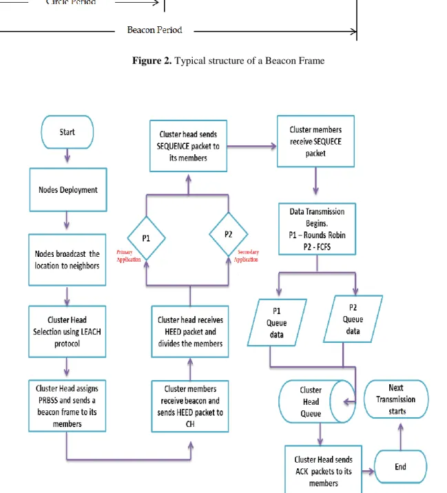
The MLS-MAC protocol consists of two phases: cluster head selection and beacon frame. The cluster head (CH) node is responsible for data transmission between their clusters members. The MLS-MAC protocol requires every cluster member to know their propagation delay between itself and neighboring nodes. In the initiatory slot, each node broadcast a position to catch on the location of an area and the node which is facile to disseminate with a high threshold is tabbed as the cluster head (CH) by adopting an energy-efficient LEACH Algorithm [24]. The cluster-based MAC protocol maximizes the lifetime of sensor nodes, rules out the overhearing and idle channel listening problems, and enlarges the coverage of the network. After determining the distance of their members, the CHs come up with an order of transmission and broadcast the initial order to their members
by using beacon frame. The beacon frame is a frame which periodically broadcast important information. There are numerous beacon periods in the frame formation of the MLS-MAC protocol. Several circles are followed for each beacon period and every circle period consists of four heuristic slots namely HEED, SEQUENCE, SCHEDULED DATA (SD) and ACK as shown in Figure 2. In order to avoid collision in the control frames, a pseudo random binary spreading sequence is assigned to each node in the network by CH [25]. In the HEED slot, when an idle sensor node wishes to transmit the data, it generates a HEED packet and pre-processes it with spreading sequence. The cluster member boxes up the information of sender's ID, receiver's ID, and total size of data packet, the task and the time flag. The “task” represents the application that occurs in the environment. For example, if a sensor node monitors the pressure parameter, it periodically transmits the data to the cluster head via HEED packet. The cluster head receives 'n' packets of HEED from their cluster members and extracts the packet from spreading sequence.
In the second slot, the CH checks the HEED packets and assigns their cluster members based on the task and put it on the queue list. The CH broadcasts the queue list and total size of data packets of each sender via SEQUENCE packet to their cluster members. After receiving a message from CH, the cluster members are ready for data transmission.
In the SD Slot, the scheduled cluster members transmit their data packets over multi-level scheduling following the new order fixed by the cluster head. The data transmission process is clearly elucidated in next section.
In the ACK Slot, the receiver acknowledges the sender, by enclosing the received packets, and the state of receiving packets. If the members do not receive the data packets correctly, then that respective member has to communicate with the channel for retransmission in the next circle.
3.2 The Working Principle of Scheduled Slot
In this phase, the cluster members transmit the packets one by one in order and carried over by Multi-level (ML) Scheduling. The ML scheduling has a pair of processes called prime queue and subordinate queue. The prime queue is utilized for a primary application, whereas subordinate queue is operated for a secondary application. After receiving a SEQUENCE packet from CH, the members are assigned in new order based on the applications that occurs in the environment.
3.2.1 Prime Queue (P1)
The primary application is achieved in the prime queue (P1) by Round Robin (RR) scheduling. The underwater sensors study the characteristics of seawater, such as acidity, conductivity, density, dissolved methane gas (METS), pressure, salinity, depletion of oxygen and temperature. In addition, torque and quantum sensors have been used to measure the light radiations and harmful algal blooms. In MLS-MAC protocol, we consider the pressure as the primary application since tsunami alerts at deep waters could be measured by the bottom pressure sensor.
predominantly used for network schedulers in computing and operating systems. This algorithm uses in the Central Processing Unit (CPU) during the execution of a process. The CPU sets a default small-scale time for all the processes which is termed as quantum or time slice. All tasks in a system are assigned to an individual process in equal allocation of time that keeps running in a roundabout order and handles all the processes without priority. The advantage of this algorithm is that it is simple, starvation-free and easy to implement. This algorithm is also applied for data packet transmission in computer networks. Moreover, the RR algorithm has the convenience of time sharing and fairness. Having these many advantages of this algorithm, we adopted round robin scheduling for primary application that runs on the P1 queue in the MLS-MAC protocol. The cluster head in MLS-MAC protocol allocates the cluster members based on the physical parameter and those members transmit the data packets via a prime queue or a subordinate queue. In P1 queue, the cluster-head set a criterion that all members of P1 queue share the equal chance to transmit the packets in a channel. The criteria could be either a time slice or the size of the data packets. The CH fixes the size of data packets as criteria for the P1 queue. So, members in the P1 queue get equal chances to transmit the data packets. The size of data packet is constant for the P1 queue and members get the chances in a circular order. If the size of data packet gets over by the first cluster member, it hands over the chances to a second cluster member in the queue to transmit the data packets. Likewise, the transmissions are passed on in the P1 queue. Therefore, members in the P1 queue get equal chances and leave the queue.
3.2.2 Subordinate Queue (P2)
The secondary application is accomplished in subordinate queue (P2) by First-Come First-Served (FCFS) scheduling. The FCFS is the simplest and non-preemptive algorithm used in CPU, computer networks, and in operating systems. This works under the mechanism of First in First out (FIFO). Whenever the processor sends a request to CPU, the process gets executed on the first-come, first-served basis. This is suitable for short jobs in the system. We take this concept for subordinate queue in the MLS-MAC protocol. Here, the cluster head does not fix any criteria on the P2 queue because, secondary application rarely occurs in the network. We consider oil slick as the secondary application in the MLS-MAC protocol.
At P2 queue, cluster members are in the order fixed by the cluster head and schedule the data according to the order. The head of the queue transmits all the data packets and discards the queue. Likewise, the second member in the queue transmits all the data packets and leaves the P2 queue. So, all members in the P2 queue transmit the data packets one by one and leave the P2 queue. The flowchart of MLS – MAC is shown in figure 3.
4.
Comparative Throughput Analysis
In this section, we showcase an approximate throughput study by using renewal theory on the traffic model that was initially presented in the CSMA protocol [26]. The average channel utilization is given by
S U
B I
(1)
Where Uis the transmission time of data packets in the channel,
B
is the expected duration of a busy period,i.e. the period of time that the channel is being utilized, andI
is the anticipated duration of an idle period. In the proposed MAC protocol, a beacon frame consists of several circles and each circle has four slots namely HEED, SEQUENCE, SCHEDULED and ACK. Transmission takes place between these slots. One entire circle is considered a busy period and the duration between one circle and the next is called an idle period, as shown in Figure.4.Proof:
A successful transmission period T is made up of a clear HEED packet followed by a SEQUENCE packet, data packet transmission period (plus the retransmission due to the packet errors) and ACK as shown in Figure. 4.
Figure 4. Transmission Periods in the MLS-MAC Protocol Accordingly, the time taken for a successful transmission T is
T
T
HEED
T
SEQ
T
SD
T
ACK,
T
T
SD
3
T
SLOT , (2)where
T
SLOT
.
is the transmission period of a control packet (HEED, SEQUENCE, and ACK) and
is the maximum propagation time. Since underwater acoustic communication is characterized by a high Bit Error Rate (BER), the data packet should be retransmitted due to errors. The data packet transmission periodT
SD
1
). 0
(
i(1
)
SD DATA SLOT e e
i
T
i T
T
P
P
1
DATA SLOTe
T
T
P
. (3)By combining (2) and (3), we get
4
(
1)
(
1)
1
SLOT DATA DATA
e
T
KT
K
d
QT
Q
d
T
P
4
(
)(
) 2
1
SLOTe
T
K
Q d
d
T
P
, (4)where K and Q denote the number of packets transmitted by the cluster members in the queue. d denotes an average propagation delay and
T
DATA
.4.1 Multilevel Data Scheduling
4.1.1 Prime Queue
We assume the model M/M/1 system for primary application which constitutes a Poisson arrival with a mean generation rate of
packets per unit time, and the tasks of a cluster member are evenly distributed by Exponential distribution. The cluster members scheduled for primary application data packets transmit in the K arrivals of the slots, and it is essential to calculate the anticipated number of K arrivals. The probability of success for a control/data packetP
Sdefines the probability that a packet does not occur in the
seconds. The arrivals of packets to the channel are Poisson with factor
, which therefore areS
P
= P{no packets arrived in the seconds} =e
KP
= P {primary application packet arrivals in a K slot} /P {at least one arrival in the slot}. (5) According to Poisson arrivals,P {P1 in a K slot} = ( ) . SLOT T K SLOT T e K
(6)P {at least one packet arrival in a slot} =
1
e
TSLOT (7)Therefore, the P1 in the K slot is
1
.
(
) .
1
SLOT SLOT T K SLOT K TT
e
P
e
K
(8)And the expected value of K is 1
.
1
SLOT SLOT K T KT
K
K P
e
. (9)The average time utilized is found the average amount of time taken to transmit the generated data packets that are sent during the busy period. Therefore, the busy period in the prime queue is given by
U
1
KT
DATA
W
F, (10) whereW
F denotes the waiting time of M/M/1 system, given by 2(1
)
FW
(11)where µ is service time and ρ is the utilization factor. 4.1.2 Subordinate Queue
We assume the model M/G/1 system for secondary application that constitutes a Poisson arrival with a mean generation rate of
packets per unit time and the tasks of a cluster member are evenly distributed by General distribution. Similarly, the cluster members scheduled for secondary application data packet transmit in the Q arrivals of the slots, and it is an imperative to find out the anticipated number of Q arrivals. The probability of Q data packets are,Q
P
= P {Secondary application packet arrivals in a Q slot} /P {at least one arrival in the slot}. (12) Therefore,1 .( ) .
1 SLOT SLOT T Q SLOT Q T T e P e Q
(13)
And the expected value of Q is
1
.
1
SLOT SLOT Q T QT
Q
Q P
e
(14)Similarly, the busy period in the P2 is,
U
2
QT
DATA
W
B, (15) whereW
Bdenotes the waiting period of the M/G/1 system1. 2(1 ) B Z W
(16)
The
Z
is the second moment random variable ofx
and
is the utilization factor which is defined as,
.The total amount of time taken for transmitting the data packets during the busy period of P1 and P2 is
U
T
DATAX
W
F
W
B,where
2
1
SLOT SLOT TT
X
e
On simplifying (11) and (16), we get
0.5
F B
c
Z
c
W
W
W
c
Here
c
1
. Substituting all the equations, the overall time taken to transmit the generated data packets that are being sent during the busy period can be obtained:
U
X
W
. (17) The anticipated interval of an idle period relies on the slot duration and the mean of available slots in an idle period. Therefore,
1
SLOT2
SLOT T
T
X
I
e
(18)Equating (4) , (17), and (18) on (1), we acquired
1
[4 ( 2)]
1 e SLOT 2
X W
S
X
T X d X
P (19)
To simplify (19), we substitute the following variables: ‘a’, the normalized propagation delay,which is denoted by
a
, and ‘b’, the normalized control packet, which is
represented by b
, and
G
is the offered load, which is defined as
.By substituting a, b, G, we obtain
1
[4( ) ( 2)]
1 e 2
X W
S
X
a b X d X
P G (20)
5.
Simulation Parameters and Assumptions
packet collisions and energy consumption were compared. We simulated the entire protocol stack of a sensor node in Aquasim [27] based on a discrete-event tool to study the characteristics of UASNs. Simulations are run with 20 nodes with a dimension of 2000 *2000 region and the transmission range of 3.5km. The transmitter power is 10 W and receive power is 0.4W. All sensor nodes are equipped with full-duplex. We use a data size of 512 bytes, and control packets of 30 bytes. The propagation speed was kept constant at 1450 m/s and the data rate was 1 Kbps. Additionally, the data transmission time was set to be δ=1 and the variables a = 1.05, b = 0.04 are obtained in the given network. Moreover, the estimation of d relies on the location of the nodes and it has the modest impact on the network throughput.
5.1 Performance Comparison in terms of Network Throughput
The network throughput is a fundamental performance metric for data link protocols. Here, the network throughput was varied with offered load. Figure 5 and Figure 6, present the overall network throughput performance of the competing MAC protocols varied with the offered load and sensor nodes.
It can be seen from Figure 5 represents the theoretical analysis of MLS-MAC protocol modeled using renewal theory and queuing theory. The network throughput of MLS-MAC peaked at about 0.77 when the offered load was close to 1.0.
Figure 5. The Network Throughput Vs Offered Load The theoretical analysis of MLS-MAC is close to the throughput in simulation. This is on the grounds that, we consider the waiting time of the Round robin and FCFS in theoretical analysis, which occurred in the queuing system to process the job. Each job in the system arrives in Poisson processes, which are executed by service mechanism and discard the queue, where the same agenda happens in the MLS-MAC protocol. In theoretical analysis, we included the exact propagation time, slot time, idle time, transmission period and service time of both the queues.
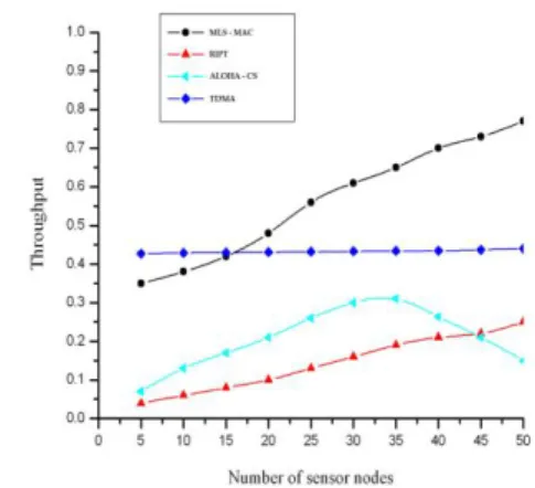
Additionally, Figure 6 shows the impact of network throughput of four MAC protocols. The throughput refers “number of packets successfully received by receiver over a period of time”.
The MLS-MAC protocol achieves the best performance among all because the protocol uses two queues to transmit the data packets. The two queues transmit one packet at a time that results two packets at receiver. The receiver can
handle one packet at a time. In order to receive two packets, the cluster head put the incoming packets in the cluster head queue. This technique helps to receive multiple packets from transmitter and increases the network throughput.
Figure 6. The Network Throughput Vs Sensor Nodes The TDMA protocol yields a constant throughput because the time slots are prearranged. On contrast, the RIPT and ALOHA-CS are contention based MAC protocols which are inherently depend on handshaking and carrier sensing that outcomes the low throughput. Moreover, the data packets in the RIPT protocol are transmitted in the form of packet trains at the receiver, from various one-hop neighbors’. As load increases in the network, the throughput of RIPT is higher than that of ALOHA, because the receiver has accurate information on its own current state.
5.2 Performance Comparison in terms of End-to-End Delay
Figure 7 illustrates the impact of end-to-end transmission delay of four MAC protocols. We observed that, with the increase of load in the network, the average end-to-end delay per packet gradually increased in all the protocols (Figure.7). This is a direct result of two reasons: firstly, with running of two queues, the transmission delay of the sensor nodes get fickle because of the transmission delay occurs in the RR and FCFS. Secondly, the delay is slightly fluctuating attributable to switching of two queues by the nodes involved in data transmission. The transmission delay of MLS-MAC is marginally lesser than RIPT and TDMA. This is because, a member in the MLS-MAC does not wait for transmitting a data packet, while the RIPT is a receiver-initiated approach, in which a node (sender) cannot transmit the data packets until a handshake is initiated by the receiver.
The ALOHA-CS achieves the best transmission delay performance among the four schemes, because it used the one-way notification mechanism for transmission.
5.3 Performance Comparison in terms of Number of Data Packet Transmission and Collision
Figure 8 shows the impact of collision overhead of four MAC protocols, and we observed that the collision overhead of these protocols increased along with the offered load.
Figure 8. The Packet Collision
The proposed protocol resulted in the low collision rate when compared with other competing MAC protocols. This is because MLS-MAC handles the multiple cluster heads to regulate the transmission order, which are set based on the priority tasks, by encasing the transmission time of each group member. So, members of the network have the knowledge about transmission time of own slot, and the neighboring member's time slots, to avoid collisions. Moreover, we observe that the collision overhead of MLS-MAC is smaller than that of RIPT and ALOHA-CS protocol, when the offered load is high. This is because members in the MLS-MAC protocol are assigned with a pseudo random binary sequence, in order to avoid collisions. When load increases in contention-based MAC protocols, the collision overhead of RIPT and ALOHA-CS marginally increases. In contrast, RIPT is a receiver-initiated protocol and sends multiple data packets in the form of train for every set of handshake. If a packet collision occurs in RIPT, a huge amount of data packets will be corrupted.
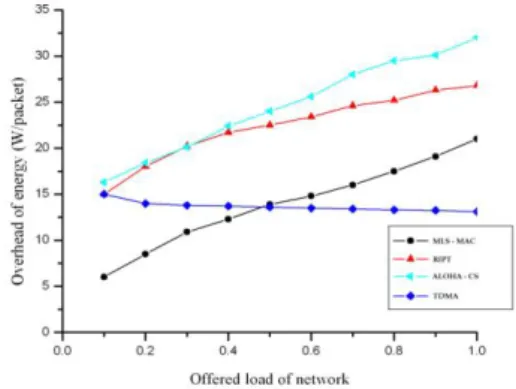
5.4 Performance Comparison in terms of Energy Consumption
Figure 9 demonstrates the energy overhead of four MAC protocols in a 20-node network. We characterize the energy overhead as the average energy spent for sensing and transmitting a data packet from sender to receiver. From Figure 9, we observed that when the offered load increases, all the energy consumption of MAC protocols increases drastically except TDMA. This is because TDMA assigns each time slot to an individual node, which helps to transmit the data packets in a given time slot. By this mechanism, it reduces the waiting time of a sensor node and out turns the static energy in the network.
The proposed MAC protocol consumes less energy than the contention-based MAC protocols. This is because MLS-MAC operates multiple cluster heads to regulate the transmission in the network, in order to avoid idle channel listening and overhearing issues. These are the main issues
that help to balance the energy in the network and maximize the lifetime of sensor nodes. From Figure 9, we noticed that ALOHA-CS consumed the highest energy in all the four MAC protocols. This is because ALOHA-CS takes more time to sense the channel, whether the channel is idle or busy, and after a random back-off time, it transmits the data packets that lead to high energy consumption.
Figure 9. The Energy Consumption
The MLS-MAC consumes less energy than other protocols because MLS-MAC adapts multiple cluster heads to regulate the transmission in order to save the energy of its members.
6.
Conclusion
This paper proposes a multilevel scheduling-based MAC protocol, to overcome idle channel listening and overhearing issues emerging in the contention-based MAC protocol, and excessive delay in schedule-based MAC protocol in UASN. We first adopted the energy-efficient clustering algorithm for the cluster head (CH) selection. The cluster head is responsible for packet transmissions in the network and aids to inflate the lifetime of sensor nodes. To enhance the channel efficiency, we came out with multilevel scheduling in data phase, which carries off two queues based on the priorities fixed by the cluster head. These two queues run concurrently in the network to transmit the multiple data packets.
Using this promising scheduling, we could eliminate the waiting time of the sensor nodes and data packets that are transmitted within short duration of time. Simulation results showed that MLS-MAC reduced the waiting time of the cluster members and achieved higher throughput than schedule-based MAC protocols. The proposed MAC protocol consumed less energy in the network compared with the contention-based MAC protocols.
References
[1] I. F. Akyildiz, D. Pompili, and T. Melodia, "Underwater acoustic sensor networks: research challenges," Ad hoc networks, Vol. 3, No.3, pp. 257-279, 2005.
[2] J. W. Lee, and H. S. Cho, "Cascading multi-hop reservation and transmission in underwater acoustic sensor networks," Sensors, Vol. 10, pp. 18390-18409, 2014.
[3] H.W. Kim, and H.S. Cho, "SOUNET: Self-organized underwater wireless sensor network," Sensors, Vol. 2, pp. 0283, 2017.
[5] H. Chen, G. Fan, L. Xie, J.H. Cui, "A Hybrid Path-Oriented Code Assignment CDMA-Based MAC Protocol for Underwater Acoustic Sensor Networks," Sensors, Vol. 11, pp. 15006-15025, 2013.
[6] W. Osamy, and A. M. Khedr. "An algorithm for enhancing coverage and network lifetime in cluster-based Wireless Sensor Networks," International Journal of Communication Networks and Information Security, Vol. 10, No.1, pp.1-9, 2018.
[7] N.Z. Zenia, M.S. Kaiser, M. R. Ahmed, S.A. Mamun, and M.S.Islam, "An energy efficient and reliable cluster-based adaptive mac protocol for uwsn," International Conference on Electrical Engineering and Information Communication Technology (ICEEICT), Dhaka, Bangladesh, pp. 1-7, 2015. [8] F. Wang, L.Wang, Y. Han, B. Liu, J. Wang and X. Su, "A
Study on the Clustering Technology of Underwater Isomorphic Sensor Networks Based on Energy Balance," Sensors, Vol. 17, pp. 12523-12532, 2014.
[9] P. Jiang, J. Liu, and F. Wu, "Node non-uniform deployment based on clustering algorithm for underwater sensor networks," Sensors, Vol. 12, pp 29997-30010, 2015.
[10] K. Chen, M.Ma, E. Cheng, F.Yuan and W.Su, "A survey on MAC protocols for underwater wireless sensor networks," IEEE Communications Surveys & Tutorials, Vol. 16, No. 3, pp. 1433-1447, 2014.
[11] S. Lmai, M. Chitre, C. Laot, and S. Houcke, "Throughput-Efficient Super- TDMA MAC Transmission Schedules in Ad Hoc Linear Underwater Acoustic Networks," IEEE Journal of Oceanic Engineering, Vol. 42, No. 1, pp. 156-174, 2016. [12] Y. Zhong, J. Huang, and J. Han,"A TDMA MAC protocol for
underwater acoustic sensor networks," IEEE Youth Conference on Information, Computing and Telecommunication, Beijing, China, pp. 534-537, 2009. [13] R. Santos, J. Orozco, S.F. Ochoa, R. Meseguer, G. Eggly and
M.F. Pistonesi, "A MAC protocol to support monitoring of underwater spaces," Sensors, Vol. 17, pp. 394 – 406, 2016. [14] L. Hong, F. Hong, Z. Guo, and Z. Li, "ECS: Efficient
communication scheduling for underwater sensor networks," Sensors, Vol. 3, pp. 2920-2938, 2011.
[15] R. Zhang, X. Cheng, X. Cheng, and L.Yang. "Interference-Free Graph Based TDMA Protocol for Underwater Acoustic Sensor Networks," IEEE Transactions on Vehicular Technology, Vol. 67, No.5, pp. 4008-4019, 2018.
[16] N. Chirdchoo, W. S. Soh, and K. C. Chua, "Aloha-Based MAC Protocols with Collision Avoidance for Underwater Acoustic Networks," IEEE INFOCOM 2007 - 26th IEEE International Conference on Computer Communications, Barcelona, Spain, pp. 2271-2275, 2007.
[17] N. Chirdchoo, W. S. Soh, and K. C. Chua, "RIPT: A Receiver-Initiated Reservation-Based Protocol for Underwater Acoustic Networks," IEEE Journal on Selected Areas in Communications, Vol. 26, No. 9, pp. 1744-1753, 2008.
[18] Z. Liao, D. Li, and J. Chen, "A handshake based ordered scheduling MAC protocol for underwater acoustic local area networks," International Journal of Distributed Sensor Networks, Vol. 1, pp. 984370, 2015.
[19] X. Feng, Z. Wang, G. Han, W. Qu, and A. Chen, "Distributed Receiver-oriented Adaptive Multichannel MAC for Underwater Sensor Networks," IEEE Access, 2018.
[20] L. Hong, F.Hong, Z.Guo, and Y.Guo, "HCR: a hybrid MAC protocol for underwater sensor networks using channel reservation," International Journal of Computers and Applications, Vol. 33, No. 2, pp. 154-159, 2015.
[21] R. Diamant and L. Lampe, "A Hybrid Spatial Reuse MAC Protocol for Ad-Hoc Underwater Acoustic Communication Networks," IEEE International Conference on Communications Workshops, Cape Town, South Africa, pp. 1-5, 2010.
[22] G. Fan, H.Chen, L. Xie, and K. Wang, "A hybrid reservation-based MAC protocol for underwater acoustic sensor networks," Ad Hoc Networks, Vol .11, No.3, pp. 1178-1192, 2013.
[23] WHOI, Micro-Modem Overview, Woods Hole
Oceanographic Institution,
http://acomms.whoi.edu/micromodem/.
[24] X .Li, Y. Wang, and J. Zhou, "An Energy-Efficient Clustering Algorithm for Underwater Acoustic Sensor Networks," International Conference on Control Engineering and Communication Technology, Liaoning, China, pp. 711-714, 2012.
[25] G. Fan, H. Chen, L.Xie, and K.Wang, “Funneling Media Access Control (MAC) Protocol For Underwater Acoustic Sensor Networks,” Journal of Zhejiang University Science C, pp.932, 2011.
[26] L. Kleinrock and F. Tobagi, "Packet Switching in Radio Channels: Part I –Carrier Sense Multiple-Access Modes and Their Throughput-Delay Characteristics," IEEE Transactionson Communications, Vol. 23, No.12, pp. 1400-1416, 1975.
Figure 2. Typical structure of a Beacon Frame