Power Steering Pumps
VT16 & VT17 Series
Overhaul Manual
Vickers
®
Steering
Table of Contents
Section Page
I. Introduction
. . .
3A. Purpose of Manual
. . .
3B. General
. . .
3Table 1. Installation Drawings and Parts Catalog Chart
. . .
3C. Physical and Operating Characteristics
. . .
3Table 2. Model Code Breakdown
. . .
3II. Description
. . .
4A. General
. . .
4B. Assembly and Construction
. . .
4C. Flow Control and Relief Valve
. . .
4Figure 1.
. . .
4D. Application
. . .
4III. Principles of Operation
. . .
4A. General
. . .
4B. Pumping Cartridge
. . .
4C. Hydraulic Balance
. . .
4Figure 2. Schematic View
. . .
5Figure 3.
. . .
5D. Flow Control and Relief Valve
. . .
5Figure 4.
. . .
6IV. Installation and Operating Instructions
. . .
6A. Drive Connections
. . .
6B. Shaft Rotation
. . .
6C. Hydraulic Tubing
. . .
6D. Hydraulic Fluid Recommendations
. . .
6Table 3. Model Code Breakdown
. . .
7E. Overload Protection
. . .
7F. Operating Instructions
. . .
8V. Service Inspection and Maintenance
. . .
8A. Service Tools
. . .
8B. Inspection
. . .
8C. Maintenance
. . .
8D. Lubrication
. . .
8E. Trouble Shooting
. . .
8Table 3. Trouble Shooting Chart
. . .
8F. Spare Parts
. . .
9VI. Overhaul
. . .
10A. Disassembly
. . .
10Figure 5.
. . .
10B. Inspection, Repair and Replacement
. . .
11C. Re-assembly
. . .
11Section I - Introduction
A. Purpose of Manual
This manual is issued as the service publication for Vickers VT16 and VT17 series Power Steering Pumps. Pumps are identified by a model code on the nameplate as belonging to the series of models covered by the model code in Table 2.
B. General
Operation, maintenance and overhaul information for the models covered by Table 2 is contained in this manual. Parts ordering information and installation dimensions are not included. Parts catalog and installation drawing numbers are listed in Table 1. Model Series Installation Drawing Parts Catalog VT16 VT17 M166357 M166358 M-1370-S Table 1.
C. Physical and Operating
Characteristics
Vickers VT16 and VT17 Pumps are primarily used to supply hydraulic fluid flow for the operation of power steering systems. These are balanced vane type, positive displacement pumps with a constant rate of delivery per revolution. The direction of pump rotation can be changed to suit specific applications. Pumps are available with an integral reservoir or with a manifold for remote reservoir locations.
7 Design
8 5 Relief Valve Setting
75 - 750 PSI 95 - 950 PSI 120 - 1200 PSI Controlled Flow Rate 15 - 1.5 GPM 25 - 2.5 GPM 30 - 3.0 GPM 40 - 4.0 GPM 50 - 5.0 GPM 1 3 4 5 6 7 1 2 6 2 3
Vane Type Steering Pump
Manifold And Reservoir 16 - Reservoir
17 - Manifold
Series
Optional Left Hand Rotation
Table 2. Model Code Breakdown. 4 Ring Capacity
15 - 1.5 GPM 40 - 4.0 GPM
Section II - Description
A. General
The VT16 and VT17 series pumps are identical in basic op-eration and performance characteristics. Differences in the individual units are covered by variables in the model num-bers illustrated in Table 2. Service inquiries and parts orders should always include the complete model number, which can be found on the pump nameplate.
B. Assembly and Construction
1. The assembly and construction of the VT16 series pumps are illustrated in cutaway in Figure 1. The unit con-sists principally of a body, cover, ring, rotor, vanes, pressure plate, relief valve sub-assembly, driveshaft and reservoir. The vanes are contained in the rotor slots and follow the cam shaped contour of the ring as the rotor is driven in rota-tion by the driveshaft. Fluid flow is developed by the vanes carrying fluid around the ring contour.
2. The VT17 series is identical to the VT16, except that in place of the reservoir, the VT17 is equipped with a man-ifold. The manifold contains a loop circuit passage for oil from the pressure side of the pump to the inlet. It also pro-vides oil line connections to the reservoir located elsewhere in the circuit.
C. Flow and Control and Relief Valve
The integral flow control and relief valve limits the fluid flow to the system to a prescribed rate. Volume greater than the rated flow is by-passed to the pump inlet. The relief valve limits the maximum pressure in the circuit.
Flow Control Valve Figure 1. Pressure Plate Ring Vane Rotor Shaft Body Cover Reservoir
D. Application
Pump ratings, methods of installation and application in-formation should be obtained from Vickers.
Section III - Principles of Operation
A. General
These units depend on the vehicle engine as a source of rotary mechanical power to produce fluid flow. Inlet flow is created by a decreased pressure set up by the action of the pumping cartridge. Flow is directed through the cartridge to the pressure port and monitored by the flow control and relief valve.
B. Pumping Cartridge
The pump cartridge consists principally of a ring, rotor and vanes (see Figure 2). The rotor is driven within the ring by a drive shaft, coupled to the power source. Radial movement of the vanes, and the rotation of the rotor, cause the cham-ber area between vanes to increase in size at the inlet (large diameter) section of the ring. This results in a low pressure, or vacuum in the chamber. This pressure differential forces oil to flow into the inlet chamber by atmospheric pressure. Oil is then trapped between the rotating vanes and is forced, through porting in the pressure plate, to the outlet and into the system as the chamber size decreases at the pressure quadrants (small diameter) section of the ring. System pres-sure fed under the vanes aspres-sures sealing contact of the vanes against the ring during normal operation.
C. Hydraulic Balance
The ring is shaped so that two pumping chambers are formed 180° apart. Thus, any hydraulic loads on the bear-ings are cancelled.
Figure 2. Schematic View Showing Oil Flow and Vickers Hydraulic Balance Construction. Cam Ring Inlet Outlet Outlet Rotor
Drive Shaft Inlet
Rotation Vane Outlet Inlet Rotation Figure 3. H F 2 G 4 3 E D B A C 1 J
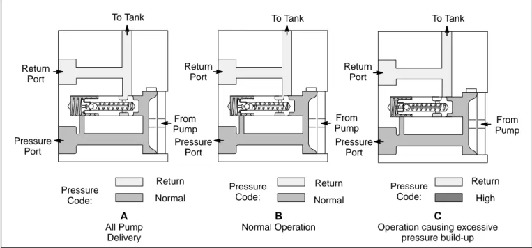
D. Flow Control and Relief Valve
1. Maximum fluid delivery and maximum system pres-sure are determined by the integral flow control and relief valve (Figure 3). The rate of flow depends on the sizes of the restriction (D) in the cover. Excess oil is ported past the slid-ing spool (1) to the return circuit by way of passage C.
2. When all pump delivery can pass through the restric-tion to the load, the spool is held in the closed posirestric-tion by the large spring (2) and passage C is blocked from chamber B. This is the condition illustrated in Figure 4-A.
3. When pump delivery is greater than the flow rate de-termined by the restriction (D), a pressure build-up in cham-ber B forces the spool open against the large spring force. Excess fluid is throttled past the spool to passage C and back to inlet, as shown in Figure 4-B.
4. Figure 4-C shows the condition when pressure in the system builds up to the relief valve setting. Pressure is trans-mitted through sensing orifices G and H and forces the ball (4) from its seat. Fluid flow is then from chamber B, through orifice D, passage E, orifices G, H and J to passage C and to inlet. The pressure drop across restriction D resulting from this flow causes a differential pressure on the spool ends and the spool is shifted against the large spring, permitting the remainder of pump delivery to flow from chamber B to passage C.
5. A second function of the valve sub-assembly and #2 is to hold the pressure plate against the pump cartridge until pressure builds up in chamber B.
Figure 4.
A
All Pump DeliveryB
Normal OperationC
Operation causing excessive pressure build-up To Tank Return Port Pressure Port Pressure Code: Return Normal From Pump To Tank Return Port Pressure Port Pressure Code: Return Normal From Pump Pressure Port Return Port To Tank From Pump Return High Pressure Code:
Section IV - Installation and Operating Instructions
A. Drive Connections
Care must be exercised in pump mounting to insure correct alignment with the driving medium. If indirect drive is used, belts and pulleys must be properly aligned and adjusted to prevent undue side loads being imposed on the shaft bearings.
B. Shaft Rotation
1. Pumps are manufactured for either right hand or left hand rotation. They must be driven in the direction of the arrow on the pump ring or severe damage may result.
2. The direction of rotation can be changed by reversing the pump ring and replacing the pressure plate with the cor-rect plate for the desired dicor-rection of rotation (see parts cata-log M-1370-S). Correct disassembly and assembly proce-dures are given in Section VI of this manual.
C. Hydraulic Tubing
1. The number of bends in tubing must be kept to a mini-mum to prevent excessive turbulence and friction of oil flow.
2. Tubing must not be bent too sharply. The minimum radius for bends is three times the inside diameter of the tube.
3. To minimize flow resistance and the possibility of leak-age, only as many fittings and connections as are necessary for proper installation should be used.
4. Tubing must not be sprung into position or undue strain will result at the connections.
5. All tubing must be thoroughly cleaned before installa-tion to remove dirt, rust and scale. Recommended methods of cleaning are sand blasting, wire brushing and pickling.
D. Hydraulic Fluid Recommendations
1. Oil Type - Oils used in hydraulic systems perform the dual function of lubrication and transmission of power. Oil must be selected with care and with the assistance of a reputable supplier.
Crankcase oils meeting or exceeding the ”Five Engine Test Sequence” for evaluating oils for API (American Petroleum Institute) service MS (Maximum Severity) best serve the needs of mobile hydraulic systems. These engine sequence tests were adopted by the Society of Automotive Engineers, American Society for Testing Materials, and automotive engine builders. The MS Classification is the key to selection of oils containing the type of compounding that will extend the operating life of the hydraulic system. Oils meeting Diesel engine requirements, DG and DS classifications, may or may not have the type of compounding desired for high performance hydraulic systems.
Good oils are the most economical. Specifications can be set up which will indicate, to a limited degree, the characteristics essential in a good hydraulic oil. These are listed herein and should be checked with the oil manufacturer prior to the use of this product.
2. Viscosity - Viscosity is the measure of fluidity. The oil must have sufficient body to provide adequate sealing effect between working parts of pumps, valving, cylinders, etc., but not enough to cause pump intake cavitation, sluggish valve action, or in extreme cases, resistance to flow. Viscosity rec-ommendations must at best be a compromise, which takes into consideration the working temperature range, the type of hydraulic equipment used, and the class of service. Refer to table of oil viscosity recommendations below.
3. Viscosity Index - The viscosity index is a measure of the rate at which temperature changes cause a change in oil viscosity. It is very desirable that the oil viscosity remain as nearly constant as possible under the wide range of temper-ature conditions encountered in operating mobile and construction machinery. The viscosity index (V.I.) of hydraulic oil should not be less that 90 for this type of service.
4. Additives - Research has developed a number of additive agents which materially improve various characteris-tics of oils for hydraulic systems. They may be selected for compounding with a view toward reducing wear, increasing chemical stability, inhibiting corrosion, depressing pour point and improving the anti-foam characteristics. Proper use of additive agents requires specialized knowledge, and they should be incorporated by the oil manufacturer only, as serious trouble may otherwise result.
Most oil companies have several brands of crankcase oils of somewhat varying formulation that will meet the API service classification of MS. The more desirable of these oils for hydraulic service will contain higher amounts of the type of compounding that avoids scuffing and wear of cam lobes and valve lifters. These oils will also be formulated to be stable under oxidative conditions and when in contact with small amounts of moisture. There should also be reasonable protection against rust to any ferrous materials submerged in the oil or covered by the oil’s film.
5. Cleanliness - Thorough precautions should be taken to filter the oil in the entire hydraulic system prior to its initial use to remove paint, metal chips, welding shot, lint, etc. If this is not done, damage to the hydraulic system will probably result. In addition, continuing filtration is required to remove sludge and products of wear and corrosion, throughout the life of the system.
Precautions should be taken in the design of hydraulic circuits to assure that a means is provided to keep the oil clean. This can best be accomplished by the use of a 25 micron full-flow filter or a 10 micron by-pass filter (not a
6. Pump Inlet Conditions - Use of an improper grade of oil or restrictive inlet piping may result in inlet vacuum condi-tions exceeding the recommended maximum 5 inches of mercury, and will reduce the life expectancy of the hydraulic equipment. Where vacuum exceeds 5 inches of mercury, and it is not caused by improper oil selection, Vickers is to be consulted.
7. Operating Temperatures - Operation in excess of 180° F. results in increased wear of the system components and causes more rapid deterioration of the oil. The hydraulic system that is designed to maintain a temperature of 160° F. or less desirable.
8. Grade - Table 3 summarizes the oil types (viscosity and service classification) that are recommended for use with Vickers equipment. This selection is most important and should be made with considerable care.
Hydraulic System Operating Range (Min. to Max.) SAE Viscosity API Service Classification 0°F. to 180°F. 15°F. to 210°F. 32°F. to 230°F. 0°F. to 210°F. 10W 20-20W 30 10W-30 MS MS MS MS Table 3.
These temperature ranges for each grade of oil are satisfactory if suitable procedures are followed for low temperature start-up conditions and if sustained operation is avoided at the upper temperature limits. For optimum operation, a maximum oil viscosity of 4000 SSU at low temperature start-up condition and a minimum oil viscosity of 60 SSU for sustained high temperature operating condition are recommended. Operation of the fluid at temperatures below 160° F. is recommended to obtain the maximum unit and fluid life.
Automatic Transmission Fluid, Type “A” is usually satisfactory for power steering systems or those systems operating under moderate hydraulic service.
E. Overload Protection
1. An integral relief valve protects the hydraulic system components by limiting the maximum pressure.
2. Relief valve sub-assemblies are pre-set and tested by Vickers for given pressure settings. Selection of the correct setting should be based on the system work requirements. If the relief setting must be changed, a replacement valve should be installed.
F. Operating Instructions
Normally these pumps require no manual priming. It is essential, however, that after starting a minimum drive speed of 400 rpm be maintained until the pump picks up its prime. Failure to observe this precaution can result in scoring and possible seizure of the pump due to a lack of oil for lubrication.
CAUTION
Do not use hydraulic brake fluid. Use only high grade hydraulic oil of the viscosities recommended in paragraph D on Hydraulic Fluid Recommenda-tions. Do not use fire resistant fluids in Vickers’ products without consulting Vickers’ application engineering personnel. O-Rings, seals and pack-ings which are not compatible with petroleum base fluids are not compatible with synthetic type fluids.
Section V - Service Inspection and Maintenance
A. Service Tools
The only special service tool required is a shaft oil seal driver. The driver is used to insure that the seal is not damaged during installation. A piece of tubular round stock should be machined so that the outside diameter is 1-5/8 inches and inside diameter is 1 inch. The tool must be at least 2-1/2 inches long and the ends must be squared.
B. Inspection
Periodic inspection of oil condition and pressure connections will ave time consuming breakdowns and unnecessary parts replacement.
1. All hydraulic connections must be tight. A loose con-nection in pressure lines will allow fluid to escape. In suction and return lines, loose connections will permit air in the pump, resulting in noisy and erratic operation.
2. System filters and reservoir should be checked for foreign particles. If contamination is found, the system should be drained.
a. The reservoir must be cleaned thoroughly before refilling. All lint particles must be removed to avoid possible clogging of system filters.
b. New oil of the proper specification, poured through a micron filter or a 200 mesh screened funnel, should be used to refill the reservoir.
C. Maintenance
1. All openings in the circuit must be properly capped if a unit is removed for service. Units removed also should be capped or plugged to prevent the entry of dirt or other for-eign matter.
2. These pumps require no adjustments other than main-taining correct shaft alignment.
D. Lubrication
Lubrication of these pumps is automatically accomplished by the hydraulic fluid.
E. Trouble Shooting
Table 4 lists the pump difficulties most commonly encountered and indicates the probable causes and remedies. It must be remembered that many apparent pump failures can actually be other units in the system. Improper operation is best diagnosed with adequate testing equipment and a thorough understanding of the complete hydraulic system.
F. Spare Parts
Only genuine parts manufactured or sold by Vickers Incorporated should be used.
TROUBLE PROBABLE CAUSE REMEDY Pump not delivering oil Driven in wrong direction of rotation.
Pump drive shaft disengaged or sheared.
Flow control valve stuck open.
Check direction of pump shaft rotation. It should rotate clockwise as viewed from the coupling end of the unit.
See also reassembly instructions for pump cartridge.
Remove pump. Determine damage to cartridge parts (see disassembly instructions). Replace sheared shaft and needed parts.
Disassemble pump and wash control valve in a clean solvent. Return valve to its bore and slide it back and forth. No stickiness in movement should occur. If a gritty feeling is noted on the valve O.D. it may be polished with a crocus cloth. Avoid removal of excess material or rounding of valve edges during this operation. Do not attempt to polish the valve bore. Wash all parts before
reassembly of pump. Fill system with clean oil per prescribed recommendations. Pump not delivering oil (Con’t) Vane or vanes stick in rotor slots.
Oil viscosity too heavy to pick up prime.
Disassemble pump. Examine rotor slots for dirt, grime or small metal chips. Clean rotor and vanes in a good grade solvent (mineral oil or kerosene). Reassemble parts and check for free vane movement. Use fluid of the proper viscosity as recommended in oil data (Table 3). Noisy pump operation Pump intake partially blocked.
Air vent for oil tank clogged or dirty strainer.
Air being drawn into pump return connection.
Leaking shaft seal.
Drain system completely. Flush to clear pump passages. Flush and refill system with clean oil as per prescribed
recommendations.
Remove filler cap and clean air vent slot. Check strainer in tank for clogged condition. Drain, flush and add clean oil to system.
Pump must receive air-free oil or pump will be noisy. Drain system. Tighten all hose connections. Clean or replace filter. Add clean oil of the proper viscosity.
Check pump shaft seal and replace if sealing lip has been damaged. Check for scoring of shaft at seal contact area. Replace faulty shaft.
Section VI - Overhaul
A. Disassembly
CAUTION
Before removing a unit to be serviced, be sure it is not under pressure.
1. General - Use a puller to remove shaft gears or pulleys to prevent damage to the shaft and bearings.
During disassembly, pay special attention to identifi-cation of parts for proper reassembly. Refer to Figure 5 for identification of parts in the following discussion.
2. Cover End - Clamp the pump mounting flange in a vise. Be certain to used protective jaws.
a. VT16 Reservoir - Remove the tank cover screw, lockwasher, washer, guide and guide gasket. Lift off the tank cover and gasket and remove the tank screws, tank, gaskets and spacers.
b. VT17 Manifold - Remove the manifold screws and manifold and lift off the gaskets and spacers. The remaining disassembly is the same for both VT16 and VT17 models.
c. Remove the cover screws and separate the cover from the pump. Remove the control valve sub-assembly and spring and the cover O-Ring.
NOTE
Control valve sub-assemblies are preset and tested by Vickers and should not be disassembled. If any part is defective, the complete sub-assembly should be replaced.
d. Remove the pressure plate. Note the position of the pump ring for reassembly. Pull out the ring locating pins and remove the ring. Remove the vanes from the rotor slots and slide the rotor off the driveshaft. Remove the body O-Ring.
3. Shaft End - Remove the driveshaft key. Remove the bearing retaining snapring and gently tap the splined end of the shaft to remove the shaft and the outboard bearing. Sup-port the outboard bearing inner race in an arbor press and press out the shaft. Remove the seal from the body with a hooked tool. Remove the inboard bearing from the shaft end of the body with a bearing puller or by tapping it out from the cover end. Figure 5. Screw Lockwasher Washer Guide Screw (Torque to 42-48 inch pounds) Cover Gasket Gasket Tank Spacer Gasket Screw (Torque to 25-30 foot pounds) Control Valve Sub-assemby Spring Pressure Plate Ring Vane O-Ring Body Bearing Shaft Snapring Bearing Gasket Spacer Key Seal Rotor Pin O-Ring Screw (Torque to 42-48 inch pounds) Manifold
B. Inspection, Repair and
Replacement
Discard all used seals and gaskets. Wash all parts in a clean mineral oil solvent and place them on a clean, lint-free surface for inspection. Soak new seals and O-Rings in hydraulic fluid prior to reasembly.
1. Cartridge, Body and Pressure Plate - Inspect all wearing surfaces for scoring. Light scoring can be removed from the body and wear plate with crocus cloth or by stoning or lapping.
Inspect the vanes for wear. Vanes must not have excessive play in the rotor slots or burred edges. Replace the vanes if they are defective. Check each rotor slot for sticky vanes or for wear. Vanes should drop in the rotor slots from their own weight when both the rotor vanes are dry.
2. Control Valve Sub-Assembly - Check that the valve moves freely in its bore in the cover and check the valve and cover bore for excessive wear and scoring. Replace both the cover and valve sub-assembly if they are deeply scored.
3. Bearing - Replace the bearings if there is any rough-ness in their action or if any race or ball is pitted, cracked or scored.
4. Driveshaft and Shaft Seal - Always replace the seal at overhaul. Check the sealing journal on the shaft for scoring. Replace the shaft if it is worn; do not install a worn shaft with a new seal.
5. Body and Cover - Stone the mating surfaces if there are any burrs or sharp edges. Rewash the parts after stoning.
C. Reassembly
1. General - Immerse all parts in clean hydraulic oil to facilitate assembly and prevent damage to seals.
2. Shaft End - Carefully seat the inboard (body) bearing in the body by pressing on the outer race. Install the
outboard bearing on the shaft by supporting the inner race
and pressing the shaft into it. Using the shaft seal driver described in Section V-A, page 7, install the shaft seal with the lip facing inward. Be sure that both bearings and the seal are properly seated. Lubricate the seal lip with petroleum jelly and slide the shaft into position. Install the snapring in the body.
3. Cover End - Support the body on blocks with the shaft end down before reassembling the pump cartridge and cover. Coat the two large O-Rings with petroleum jelly and install them in the grooves in the body and cover.
a. Place the ring against the pump body so that the cam contour is the same as at disassembly and the arrows point in the correct direction of rotation. Install the rotor and insert the vanes in the rotor so that the radiused edges are against the ring cam. Position the pressure plate over the locating pins. Be sure the plate is flat against the ring.
b. Insert the spring in the cover bore and install the control valve, small land toward the cartridge. Install the cover over the pressure plate and flush against the ring. Install the cover screws and tighten them to 25-30 foot pounds torque. Turn the drive shaft through by hand to be sure it does not bind.
c. VT17 Manifold - Place the manifold gaskets and spacers on top of the pump and install the manifold and screws. Torque tighten the screws to 42-48 inch pounds.
d. VT16 Reservoir - Place the gaskets and spacers on top of the pump and install the tank and tank screws. Torque tighten the screws to 42-48 inch pounds. Plug the ports in the pump cover and fill the reservoir with clean hydraulic fluid poured through a micron filter. Turn the driveshaft several times in the proper direction of rotation to fill all the pump chambers and then refill the reservoir. Install the tank cover gasket and cover. Assemble the bolt guide and gasket and install the guide in the cover. Assemble the lockwasher and washer on the cover screw and install and tighten the screw.
Section VII - Testing of VT16 and VT17 Pumps
Vickers application engineering personnel should be con-sulted for recommendations on test stand circuit require-ments and construction. If test equipment is available pumps should be tested at speeds and pressures shown on installa-tion drawings. (See Table 1.)