1
What Is a Virtual Private Network?
A virtual private network (VPN) allows the provisioning of private network services for an organization or organizations over a public or shared infrastructure such as the Internet or service provider backbone network. The shared service provider backbone network is known as the VPN backbone and is used to transport traffic for multiple VPNs, as well as possibly non-VPN traffic.
VPNs provisioned using technologies such as Frame Relay and Asynchronous Transfer Mode (ATM) virtual circuits (VC) have been available for a long time, but over the past few years IP and IP/Multiprotocol Label Switching (MPLS)-based VPNs have become more and more popular.
This book focuses on describing the deployment of IP- and IP/MPLS-based VPNs. The large number of terms used to categorize and describe the functionality of VPNs has led to a great deal of confusion about what exactly VPNs are and what they can do. The sections that follow cover VPN devices, protocols, technologies, as well as VPN categories and models.
VPN Devices
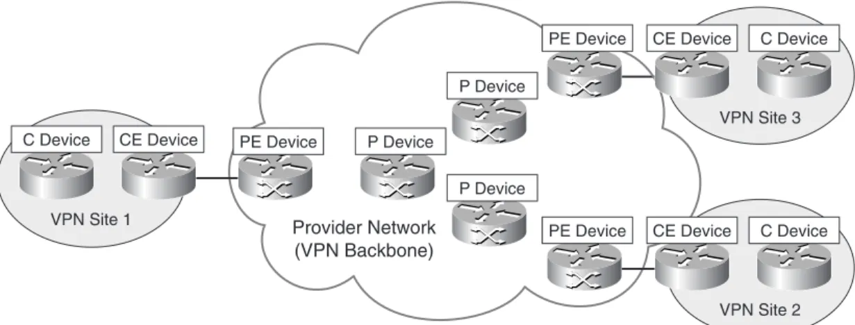
Before describing the various VPN technologies and models, it is useful to first describe the various customer and provider network devices that are relevant to the discussion. Devices in the customer network fall into one of two categories:
•
Customer (C) devices—C devices are simply devices such as routers and switches located within the customer network. These devices do not have direct connectivity to the service provider network. C devices are not aware of the VPN.•
Customer Edge (CE) devices—CE devices, as the name suggests, are located at the edge of the customer network and connect to the provider network (via Provider Edge [PE] devices).In CE-based VPNs, CE devices are aware of the VPN. In PE-based VPNs, CE devices are unaware of the VPN.
CE devices are either categorized as Customer Edge routers (CE-r), or Customer Edge switches (CE-s).
In a site-to-site VPN, devices in the service provider network also fall into one of two categories:
•
Service Provider (P) devices—P devices are devices such as routers and switches within the provider network that do not directly connect to customer networks. P devices are unaware of customer VPNs.•
Service Provider Edge (PE) devices—PE devices connect directly to customer networks via CE devices. PE devices are aware of the VPN in PE-based VPNs, but are unaware of the VPN in CE-based VPNs.There are three types of PE device: — Provider Edge routers (PE-r) — Provider Edge switches (PE-s)
— Provider Edge devices that are capable of both routing and switching (PE-rs) Figure 1-1 illustrates customer and provider network devices.
Figure 1-1 Customer and Provider Network Devices
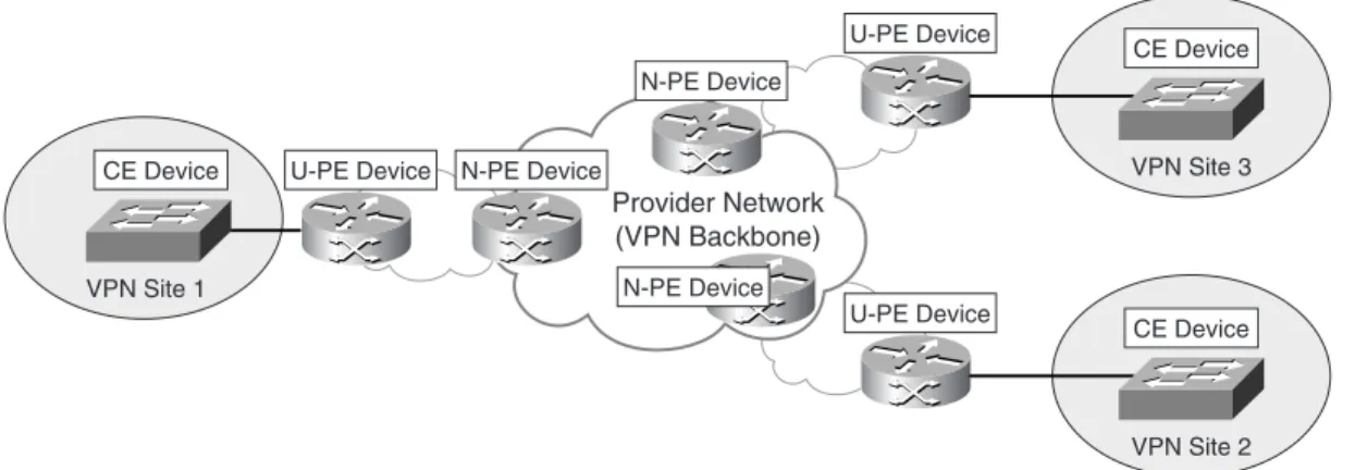
In Layer 2 VPNs, such as a Virtual Private LAN Service (VPLS), an additional level of hierarchy can be introduced into the network to improve scalability (VPLS then becomes Hierarchical VPLS [H-VPLS]). In this case, the functionality of the PE device is divided between a User-facing PE (U-PE) devices and Network-facing PE (N-PE) devices. Note that alternative (and dated) equivalent terms for the U-PE and N-PE are PE-CLE and PE-POP, respectively. In addition, where a Layer 2 PE-U device is installed in a multitenant building, this may be referred to as an MTU-s. Figure 1-2 illustrates U-PE and N-PE devices. CE Device VPN Site 1 CE Device C Device VPN Site 3 C Device CE Device VPN Site 2 C Device PE Device PE Device PE Device P Device P Device P Device Provider Network (VPN Backbone)
Figure 1-2 User-Facing and Network-Facing PE Devices
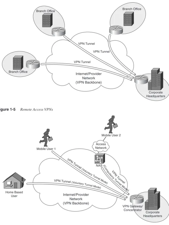
Other device types used in VPNs include Network Access Servers (NAS) and VPN gateways/concentrators. A NAS is a device that interfaces between an access network (such as a Public Switched Telephone Network [PSTN]) and a packet-switched network (such as an IP backbone). In a remote access VPN, a NAS can serve as a tunnel endpoint.
Note that depending upon the remote access VPN protocol in use, the NAS may variously be called a Layer Two Forwarding (L2F) Protocol NAS, a Layer Two Tunneling Protocol (L2TP) Access Concentrator (LAC), or a Point-to-Point Tunneling Protocol (PPTP) Access Concentrator (PAC).
See Figure 1-5 for an illustration of the role performed by a NAS.
A VPN gateway/concentrator acts as the endpoint of a VPN tunnel, especially in a remote access VPN or CE-based site-to-site VPN. See Figure 1-5 later in the chapter for an illustration of the role performed by a VPN gateway/concentrator.
Depending on the remote access VPN protocol in use, the VPN gateway/concentrator may, for example, be called an L2F Home Gateway, an L2TP Network Server (LNS), or a PPTP Network Server (PNS).
VPN Technologies and Protocols
A number of technologies and protocols are used to enable site-to-site and remote access VPNs. These protocols and technologies are described in the sections that follow.
Technologies and Protocols Used to Enable Site-to-Site VPNs
In site-to-site VPNs (discussed later in this chapter), customer user data traffic is either tunneled between CE devices or between PE devices.
U-PE Device VPN Site 3 CE Device VPN Site 1 U-PE Device N-PE Device U-PE Device N-PE Device Provider Network (VPN Backbone) N-PE Device CE Device VPN Site 2 CE Device
NOTE Site-to-site VPNs are also occasionally referred to as LAN-to-LAN VPNs.
Protocols and technologies used to enable site-to-site VPNs include IP Security (IPsec), Generic Routing Encapsulation (GRE), the Layer Two Tunneling Protocol version 3 (L2TPv3), Draft Martini pseudowires (emulated circuits), IEEE 802.1Q tunneling (Q-in-Q), and MPLS Label Switched Paths (LSP). These protocols and technologies are described as follows:
•
IPsec—IPsec consists of a suite of protocols designed to protect IP traffic between security gateways or hosts as it transits an intervening network. IPsec tunnels are often used to build a site-to-site between CE devices (CE-based VPNs).•
GRE—GRE can be used to construct tunnels and transport multiprotocol traffic between CE devices in a VPN. GRE has little or no inherent security, but GRE tunnels can be protected using IPsec.•
Draft Martini (Any Transport over MPLS [AToM])—Draft Martini transport allows point-to-point transport of protocols such as Frame Relay, ATM, Ethernet, Ethernet VLAN (802.1Q), High-Level Data Link Control (HDLC), and PPP traffic over MPLS.•
L2TPv3—L2TPv3 allows the point-to-point transport of protocols such as Frame Relay, ATM, Ethernet, Ethernet VLAN, HDLC, and PPP traffic over an IP or other backbone.•
IEEE 802.1Q tunneling (Q-in-Q)—802.1Q tunneling allows a service provider to tunnel tagged Ethernet (802.1Q) customer traffic over a shared backbone. Customer 802.1Q traffic is tunneled over the shared provider backbone by prepending another 802.1Q tag.•
MPLS LSPs—An LSP is a path via Label Switch Routers (LSR) in an MPLS network. Packets are switched based on labels prepended to the packet. LSPs may be signaled using the Tag Distribution Protocol (TDP), the Label Distribution Protocol (LDP), or the Resource Reservation Protocol (RSVP).Technologies and Protocols Used to Enable Remote Access VPNs
Protocols used to enable remote access VPNs (discussed later in this chapter) include the following:
•
The Layer Two Forwarding (L2F) Protocol—L2F is a Cisco proprietary protocol that is designed to allow the tunneling of PPP (or Serial Line Interface Protocol [SLIP]) frames between a NAS and a VPN gateway device located at a central site. Remote access users connect to the NAS, and the PPP frames from the remote access user are then tunneled over the intervening network to the VPN (home) gateway.•
The Point-to-Point Tunneling Protocol (PPTP)—PPTP is a protocol that was developed by a consortium of vendors, including Microsoft, 3Com, and Ascend Communications. Like L2F, PPTP allows the tunneling of remote access client PPP frames between a NAS and a VPN gateway/concentrator. PPTP also allows a tunnel to be set up directly from a remote access client to a VPN gateway/concentrator. PPP encapsulated packets carried over PPTP tunnels are often protected using Microsoft Point-to-Point Encryption (MPPE).•
The Layer 2 Tunneling Protocol versions 2 and 3 (L2TPv2/L2TPv3)—L2TP is an Internet Engineering Task Force (IETF) standard and combines the best features of L2F and PPTP. In a remote access environment, L2TP allows either tunneling of remote access client PPP frames via a NAS to a VPN gateway/concentrator or tunneling of PPP frames directly from the remote access client to the VPN gateway/ concentrator.L2TP has limited intrinsic security, and so L2TP tunnels are often protected using IPsec.
•
IPsec—As well as enabling site-to-site VPNs, IPsec can also be used to securely tunnel data traffic between remote access or mobile users and a VPN gateway/ concentrator.•
The Secure Sockets Layer (SSL)—SSL is a security protocol that was originally developed by Netscape Communications (SSL versions 1, 2, and 3), and it provides secure remote access for mobile users or home users. Functionality may be limited (when compared with L2F, PPTP, L2TPv2, or IPsec) if clientless SSL remote access VPNs are deployed.Note that Transport Layer Security (TLS), an IETF standard, is similar to SSLv3. In spite of the limited functionality provided by clientless SSL VPNs, one advantage of this type of remote access VPN is that no special client software is required because SSL is included in pretty much every web browser. Therefore, if a remote user has a web browser, the user has SSL client software. Because no special client software is required other than a web browser, SSL VPNs are sometimes referred to as webVPNs or clientlessVPNs.
More functionality may be added to SSL VPNs by installing specific SSL VPN client software on remote access client devices.
Modeling and Characterizing VPNs
A plethora of methods are used to model and characterize VPNs. The purpose of this section is to introduce and explain each of these models and characterizations.
As you read this section, you may ask yourself how it is that we have ended up with so many terms to describe VPNs. The answer is a desire to accurately describe the characteristics of a VPN protocol or technology but also a simple lack of coordination among protocol
designers and engineers (this is getting much better), and on top of that a certain amount of “help” from our marketing colleagues (“How can I differentiate our products?”).
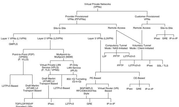
As you read this section, be sure to refer to Figure 1-3. Figure 1-3 clarifies the relationship of the VPN models to each other; it also describes the VPN (tunneling) protocols and technologies associated with the various models.
The bottom level of the hierarchy in Figure 1-3 describes protocols or mechanisms used to tunnel VPN traffic between CE or PE devices.
Figure 1-3 Virtual Private Networks
Note that in Figure 1-3, F: denotes a former name for a particular technology.
Service Provider and Customer Provisioned VPNs
VPNs can be either one of the following:•
Service provider provisioned—VPNs that are configured and managed by a service provider or providers•
Customer provisioned—VPNs that are configured and managed by the (service provider) customer itselfGRE Virtual Private Networks
(VPNs)
Provider Provisioned VPNs (PPVPNs)
Customer Provisioned VPNs
Site-to-Site Remote Access
Point-to-Point (P2P) (VPWS) (F: VLLS) Multipoint-to-Multipoint (M2M) Draft Martini (AToM) L2 Transport Based L2TPv3 Based Virtual Private LAN
Service (VPLS) (F: TLS / VPNS) IP-Only LAN Service (IPLS) Layer 2 VPNs (L2VPN) Layer 3 VPNs (L3VPN) PE-Based CE-Based BGP/MPLS RFC4364/2547bis Style Virtual Router (VR)
Based IPsec GRE
Site-to-Site Remote Access Compulsory Tunnel Mode / NAS-Initiated Voluntary Tunnel Mode / Client-Initiated L2F PPTP L2TPv2/v3 L2TPv2/v3 PPTP IPsec SSL / TLS IPsec 802.1Q Tunneling (Q-in-Q) Draft Martini (AToM) L2 Transport Based L2TPv3 Based TDP/LDP/RSVP Signalled LSPs
IPsec L2TPv3 GRE IP-in-IP
IP-in-IP
IP-in-IP Layer 1 VPNs (L1VPN)
Note that the customer of the service provider may be either an enterprise or another service provider, in which case, the service provider that offers the VPN service is known as a carrier of carriers, and the service offered to the customer service provider is known as a carrier’s carrier VPN service.
Additionally, a VPN service might be offered over the backbone networks of multiple cooperating autonomous systems and/or service providers. In this case, the VPN service is known as an inter-AS or interprovider VPN service.
Examples of provider provisioned VPNs are as follows:
•
Virtual Private Wire Service (VPWS) VPNs•
Virtual Private LAN Service (VPLS) VPNs•
IP-Only Private LAN Service (IPLS) VPNs•
BGP/MPLS (RFC4364/2547bis) VPNs (BGP/MPLS VPNs are also known as MPLS Layer 3 VPNs.)•
Virtual Router (VR)-based VPNs•
IPsec VPNsExamples of customer provisioned VPNs are as follows:
•
GRE VPNs•
IPsec VPNsSite-to-Site and Remote Access VPNs
VPNs, whether provider or customer provisioned, fall into one of two broad categories:
•
Site to site•
Remote accessSite-to-site VPNs allow connectivity between an organization’s (or organizations’) geographically dispersed sites (such as a head office and branch offices).
Figure 1-4 illustrates a typical site-to-site VPN. There are two types of site-to-site VPN:
•
Intranet VPNs—Allow connectivity between sites of a single organization•
Extranet VPNs—Allow connectivity between organizations such as businesspartners or a business and its customers
Remote access VPNs (also called access VPNs) allow mobile or home-based users to access an organization’s resources remotely.
Figure 1-4 Typical Site-to-Site VPN
Figure 1-5 Remote Access VPNs
Corporate Headquarters VPN Tunnel VPN Tunnel VPN Tunnel Internet/Provider Network (VPN Backbone) Branch Office Branch Office Branch Office Corporate Headquarters VPN Gateway/ Concentrator NAS Access Network Internet/Provider Network (VPN Backbone) VPN Tunnel(Voluntary T unnel Mode) VPN Tu nnel (Vo luntary Tun nel Mode) V P N Tu nnel (C om pu lsor y Tu nn elM od e) Mobile User 1 Mobile User 2 Home Based User
Service Provider Provisioned Site-to-Site VPNs
Service provider provisioned site-to-site VPNs (PPVPN) fall into one of three categories: Layer 1 VPNs, Layer 2 VPNs, and Layer 3 VPNs. Layer 2 and Layer 3 site-to-site VPN types are described in the sections that follow.
NOTE Layer 1 VPNs are used to transport Layer 1 services over an intervening shared network controlled and managed by Generalized Multiprotocol Label Switching (GMPLS). At the time of this writing, the development of L1VPNs is in its relative infancy, and so L1VPNs are not discussed further in this book.
Layer 2 VPNs
Layer 2 site-to-site VPNs (L2VPN) can be provisioned between switches, hosts, and routers and allow data link layer connectivity between separate sites. Communication between customer switches, hosts, and routers is based on Layer 2 addressing, and PE devices perform forwarding of customer data traffic based on incoming link and Layer 2 header information (such as MAC address, Frame Relay Data Link Connection Identifier [DLCI], and so on).
There are two categories of provider provisioned L2VPN:
•
Point-to-point (P2P) circuit-based VPNs—P2P-based VPNs are also known as Virtual Private Wire Service(VPWS) VPNs and are constructed using, for example, Draft Martini (MPLS) or L2TPv3 pseudowires (emulated circuits).It is worth noting that VPWS was formerly known as Virtual Leased Line Service (VLL service or VLLS).
•
Multipoint-to-multipoint (M2M) VPNs—M2M VPNs come in two varieties: — Virtual Private LAN Service (VPLS) VPNs— IP-Only LAN Service (IPLS) VPNs
Layer 3 VPNs
Layer 3 site-to-site VPNs (L3VPN) interconnect hosts and routers at separate customer sites. These customer hosts and routers communicate based on Layer 3 (network layer) addressing, and PE devices forward customer traffic based on incoming link, and on addresses contained in the (outer) IP header.
There are two overall types of L3VPN:
•
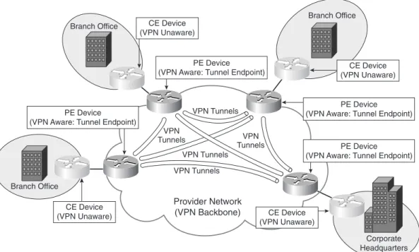
PE-based VPNs—In a PE-based L3VPN, PE devices participate in customer network routing and forward traffic based on customer network addressing. Customer traffic is (usually) forwarded between PE devices over VPN tunnels that may take the form of (MPLS) LSPs, IPsec tunnels, L2TPv3 tunnels, or GRE tunnels, for example. In this case, CE devices are not aware that they are participating in a VPN.PE-based VPNs are also sometimes referred to as Network-basedVPNs. PE-based L3VPNs can be further classified as follows:
— RFC4364/2547bis style—In this type of PE-based L3VPN, the PE devices maintain separate routing and forwarding tables for each VPN. Customer routes are advertised between PE devices using Multiprotocol Border Gateway Protocol (MP-BGP), and customer address space and routes are disambiguated using BGP attributes.
— Virtual Router (VR) based—In this type of PE-based L3VPN, completely separate logical routers are maintained on the PE devices for each VPN. Each logical router maintains its own entirely separate routing protocol instances.
Figure 1-6 illustrates a typical PE-based VPN. Figure 1-6 Typical PE-Based Site-to-Site VPN
Corporate Headquarters VPN Tunnels VPN Tunnels VPN Tunnels VPN Tunnels VPN Tunnels Provider Network (VPN Backbone) Branch Office Branch Office
Branch Office CE Device (VPN Unaware) CE Device (VPN Unaware) CE Device (VPN Unaware) PE Device (VPN Aware: Tunnel Endpoint)
PE Device (VPN Aware: Tunnel Endpoint) PE Device
(VPN Aware: Tunnel Endpoint)
PE Device (VPN Aware: Tunnel Endpoint)
CE Device (VPN Unaware)
•
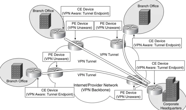
CE-based VPNs—In a CE-based L3VPN, PE devices do not participate in (and are unaware of) customer network routing and forward customer traffic based on globally unique addressing. In this case, tunnels are configured between CE devices using protocols such as GRE and IPsec.CE-based VPNs are also sometimes referred to as CPE-basedVPNs. Figure 1-7 illustrates a typical CE-based site-to-site VPN.
Figure 1-7 Typical CE-Based Site-to-Site VPN
Customer Provisioned Site-to-Site VPNs
Customer provisioned site-to-site VPNs are configured on CE devices such as routers and firewalls. In this case, tunnels are configured between CE devices in the VPN, and customer data traffic is sent over these tunnels. Protocols used to encapsulate user data traffic as it is sent over the tunnels between VPN sites include GRE and IPsec.
Service Provider and Customer Provisioned Remote Access VPNs
Remote access VPNs can be configured in either compulsory tunnel mode or voluntary tunnel mode. These two modes of operation are described as follows:
•
Compulsory tunnel mode—Compulsory tunnel mode remote access VPNs are service provider provisioned. In this mode of operation, the remote access clientCorporate Headquarters VPN Tunnel VPN Tunnel VPN Tunnel Internet/Provider Network (VPN Backbone) Branch Office Branch Office Branch Office PE Device (VPN Unaware) PE Device (VPN Unaware) PE Device (VPN Unaware) PE Device (VPN Unaware) CE Device (VPN Aware: Tunnel Endpoint)
CE Device
(VPN Aware: Tunnel Endpoint)
CE Device (VPN Aware: Tunnel Endpoint)
CE Device (VPN Aware: Tunnel Endpoint)
connects to a NAS that then tunnels client data traffic to and from a VPN gateway. Compulsory tunnel mode remote access VPNs are provider provisioned. Examples of protocols used to provision compulsory tunnel mode remote access are L2F, PPTP, and L2TP.
In Figure 1-5, mobile user 2 is connected via a compulsory mode tunnel to the VPN gateway/concentrator.
Compulsory tunnel mode remote access VPNs are sometimes referred to as NAS-initiatedremote access VPNs.
•
Voluntary tunnel mode—Voluntary tunnel mode remote access VPNs are either service provider or customer provisioned. In this mode of operation, data traffic is tunneled directly between the remote access client and a VPN gateway. Voluntary tunnel mode remote access VPNs can be either customer or provider provisioned. In Figure 1-5, the home-based user and mobile user 1 are both connected to the VPN gateway/concentrator via voluntary mode tunnels.Note that voluntary tunnel mode remote access VPNs are sometimes referred to as client-initiatedremote access VPNs.
One type of remote access VPN is a Virtual Private Dialup Network (VPDN). This term can be used to describe remote access VPNs (L2F, PPTP, and L2TP) in which remote users connect over a PSTN or Integrated Services Digital Network (ISDN) to a dial NAS. User data traffic is then tunneled to a VPN gateway. With so many remote users now connecting over cable, Digital Subscriber Line (DSL), and other high-speed connections, rather than via dial connections, this term is slightly outdated.
Other Methods of Categorizing VPNs
Yes, there are yet more methods of categorizing VPNs! VPNs can be further categorized depending on whether they are connection oriented or connectionless, whether they are overlay or peer to peer, and whether they are secure or trusted.
Overlay and Peer-to-Peer VPNs
A VPN can be categorized as either an overlay or peer VPN depending on whether PE devices are aware of customer network addressing, and route customer traffic based on customer network address space.
Overlay and peer VPNs are summarized as follows:
•
Overlay VPNs—In an overlay network, a VC or tunnel connects CE devices. No routing information is exchanged with the service provider, and PE devices are unaware of customer network address space and do not route customer traffic based on customer network addressing.Examples of overlay VPNs include those built using Frame Relay or ATM virtual circuits, as well as those built using GRE or IPsec tunnels.
•
Peer VPNs—In a peer VPN, PE devices are aware of customer network addressing and route customer data traffic according to customer network addressing. In peer VPNs, routes are exchanged between CE devices and PE devices.Older types of peer VPN often involve PE devices partitioning customer data traffic by simply using access control lists (ACL). A more modern example of peer VPNs is BGP/MPLS (RFC4364/2547bis) VPNs.
Connection-Oriented and Connectionless VPNs
VPNs can be either connection oriented or connectionless depending on whether VCs or tunnels are provisioned to carry VPN traffic.
Connection-oriented and connectionless VPNs are described as follows:
•
Connection-oriented VPNs—In connection-oriented VPNs, VCs or tunnels are set up to carry VPN traffic.Examples of connection-oriented VPNs are those provisioned using Frame Relay or ATM VCs, as well as those provisioned using L2TP or IPsec tunnels.
•
Connectionless VPNs—In connectionless VPNs, neither VCs nor tunnels are set up to carry VPN traffic.PE-based VPNs that rely on the partitioning of customer data traffic by using ACLs configured on PE devices are connectionless VPNs.
Trusted and Secure VPNs
VPNs can be described as being either trusted or secure. Whether a VPN is trusted or secure depends on whether customer data traffic is authenticated and encrypted as it passes between VPN peers (sites in an site-to-site VPN, or a remote access client and a VPN gateway/concentrator in a remote access VPN).
Trusted and secure VPNs are described as follows:
•
Trusted VPNs—Provisioned by a service provider, and although customer traffic is not encrypted over the service provider backbone, customers trust the service provider to ensure that data traffic is kept secure in transit between the customer’s sites. Examples of trusted VPNs are Frame Relay, ATM, and BGP/MPLS(RFC4364/2547bis) VPNs.
•
Secure VPNs—Customer data traffic data is authenticated and encrypted over the service provider backbone or Internet between VPN peers.Examples of secure VPNs are IPsec VPNs, SSL VPNs, PPTP VPNs secured with MPPE, and L2TP VPNs secured using IPsec.
And Finally. . .
And finally, here are two or three sundry VPN classifications:
•
Transport/Application Layer VPNs—SSL sits on top of TCP in the protocol stack, and SSL VPNs are therefore sometimes referred to as either Transport or Application Layer VPNs.•
Internet VPNs—Designed to run over the public Internet.•
Multiservice VPNs—Provide a framework for converged services, including voice, video, and data.Deploying Site-to-Site and Remote Access VPNs:
A Comparison
So now you know the VPN protocols and technologies, and how they are categorized, but how do they compare? Included in this section are comparisons of site-to-site as well as remote access VPN technologies.
Before comparing the various VPN technologies, however, it is worth noting that these VPN technologies are often complementary. For example, although it might seem that BGP/MPLS (RFC4364/2547bis) VPNs and IPsec VPNs are competing provider provisioned site-to-site VPN technologies, IPsec tunnels can, in fact, be used to tunnel VPN traffic between PE routers in an BGP/MPLS (RFC4364/2547bis) VPN backbone. IPsec and L2TP can additionally be used to provide off-net (remote access) for mobile or home-based users to a BGP/MPLS (RFC4364/2547bis) VPN.
Similarly, although it appears GRE and IPsec are competing customer provisioned site-to-site VPN technologies, in fact, hybrid GRE/IPsec VPNs are commonly deployed. Hybrid GRE/IPsec VPNs are often deployed because GRE has little or no inherent security, whereas IPsec can provide strong security. On the other hand, IPsec cannot transport multiprotocol, whereas GRE can. So, by deploying a GRE over IPsec site-to-site VPN, you combine multiprotocol with strong security—the best of both worlds!
Site-to-Site VPN Deployment
Figure 1-3 shows a number options for provider provisioned, as well as customer provisioned, site-to-site VPNs.
Provider provisioned site-to-site VPNs can be either L2VPNs or L3VPNs, as follows:
•
L2VPNs—VPWS, VPLS, and IPLS•
L3VPNs—BGP/MPLS (RFC4364/2547bis), VR, IPsec, GRE, and IP-in-IP Customer provisioned site-to-site VPNs can be deployed using the following protocols:•
IPsec•
GREWhen comparing both provider and customer provisioned site-to-site VPNs, it is important to consider a number of factors. Some of the most important technical considerations for service providers and customers when deploying site-to-site VPNs are as follows:
•
Point-to-point or multipoint—Is point-to-point or multipoint (any-to-any) connectivity inherent?•
Provisioning topologies—How easy is it to deploy a full range of topologies such as full mesh, hub and spoke, partial mesh.•
Scalability—How easy is it to deploy a VPN with a large number of sites?•
Geographic reach—Is geographic reach limited to a service provider backbone, or can it be extended across the Internet?•
Security—Is traffic authenticated and encrypted? Is traffic crossing the VPN vulnerable to replay attacks? Is traffic resistant to insertion attacks (where malicious data is inserted into the protocol stream)?•
Inherent multicast support—Can multicast traffic be natively supported across the VPN?•
Inherent multiprotocol support—Can multiprotocol traffic (including legacy protocols such as IPX) be transported?•
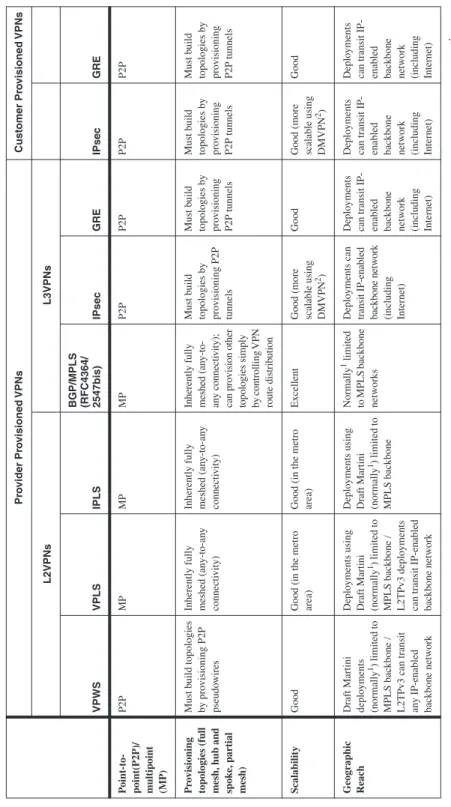
Quality of service (QoS) support—How does this technology differentiate levels of service for voice, video, and data applications?Table 1-1 shows how these considerations apply to the various site-to-site VPN technologies.
Remote Access VPN Deployment
When deploying remote access VPNs, it is also important to have an understanding of how the various technologies compare. For this reason, a technical comparison of the various remote access VPN technologies is included in this section.
Compulsory tunnel mode/NAS-initiated remote access VPNs can be deployed using the following protocols:
•
L2F•
PPTP•
L2TPv2/L2TPv3Voluntary/client-initiated remote access VPNs can be deployed using the following protocols:
•
PPTP•
L2TPv2/L2TPv3•
IPsecTa
b
le 1-1
Te
chnical Consider
ations for Site-to-Site
VPN T ec hnolo gies Pr o vider Pr o visioned VPNs Customer Pr o visioned VPNs L2VPNs L3VPNs VPWS VPLS IPLS BGP/MPLS (RFC4364/ 2547bis) IPsec GRE IPsec GRE P oint-to-point(P2P)/ multipoint (MP) P2P MP MP MP P2P P2P P2P P2P Pr o visioning
topologies (full mesh, hub and spok
e, partial mesh) Must b uild topologies by pro visioning P2P pseudo wires
Inherently fully meshed (an
y-to-an
y
connecti
vity)
Inherently fully meshed (an
y-to-an
y
connecti
vity)
Inherently fully meshed (an
y-to-an y connecti vity); can pro vision other
topologies simply by controlling
VPN route distrib ution Must b uild topologies by pro visioning P2P tunnels Must b uild topologies by pro visioning P2P tunnels Must b uild topologies by pro visioning P2P tunnels Must b uild topologies by pro visioning P2P tunnels Scalability Good
Good (in the metro area) Good (in the metro area)
Excellent
Good (more scalable using DMVPN 2)
Good
Good (more scalable using DMVPN 2)
Good
Geographic Reach Draft Martini deplo
yments
(normally
1) limited to
MPLS backbone / L2TPv3 can transit any IP-enabled backbone netw
ork
Deplo
yments using
Draft Martini (normally 1) limited to
MPLS backbone / L2TPv3 deplo
yments
can transit IP-enabled backbone netw
ork
Deplo
yments using
Draft Martini (normally 1) limited to MPLS backbone Normally 1 limited to MPLS backbone netw orks Deplo yments can
transit IP-enabled backbone netw
ork
(including Internet)
Deplo
yments
can transit IP- enabled backbone netw
ork
(including Internet)
Deplo
yments
can transit IP- enabled backbone netw
ork
(including Internet)
Deplo
yments
can transit IP- enabled backbone netw
ork
(including Internet)
Security Draft Martini deplo
yments: good
(comparable to FR/ ATM netw
orks);
L2TPv3 deplo
y-ments: good (tunnel authentication/64-bit cookie enables resistance to blind insertion attacks/ excellent protection with IPsec [per RFC3193])
Deplo
yments using
Draft Martini: good (comparable to FR/ ATM netw
orks);
deplo
yments using
L2TPv3: good (tunnel authenti-cation/64-bit cookie enables resistance to blind insertion attacks/ excellent protection with
IPsec
[perRFC3193])
Deplo
yments using
Draft Martini: good (comparable to Frame Relay/A
TM netw
orks)
Good (comparable to Frame Relay/ ATM netw
orks)
Excellent (depending on IPsec transforms deplo
yed)
Poor
Excellent (depending on IPsec transforms deplo
yed) Poor Inher ent multicast support Ye sY es Y es
No (enable with Multicast VPNs [MVPNs] or GRE tunnels between CEs) No (enable with GRE/IPsec)
Ye
s
No (enable with GRE/IPsec)
6 Ye s Inher ent multipr otocol support Ye sY es No (IP only)
No (requires mesh of CE-CE GRE tunnels) No (enable with GRE/IPsec or Virtual T
unnel
Interf
ace [VTI])
Ye
s
No (enable with GRE/IPsec or Virtual T
unnel Interf ace [VTI]) Ye s QoS Support
Draft Martini (MPLS backbone): traf
fic
dif
ferentiation
dependent on EXP
3
bits (E-LSPs) or labels (L-LSPs) /
hard QoS guarantees with TE 4 and f ast reroute; L2TPv3 - T oS 5 bits mark ed
Using Draft Martini (MPLS backbone): traf
fic dif
ferentiation
dependent on EXP bits (E-LSPs) or labels (L-LSPs) /
hard QoS
guarantees
with TE
and f
ast reroute; using
L2TPv3- T
oS
bits
mark
ed
Using Draft Martini (MPLS backbone): traf
fic dif
ferentiation
dependent on EXP bits (E-LSPs) or labels (L-LSPs) / hard QoS guarantees with
TE and f ast reroute MPLS backbone: traf fic dif
ferentia-tion dependent on EXP bits (E-LSPs) or labels (L-LSPs) / hard QoS guarantees with
TE and f
ast
reroute
T
oS bits copied to outer IP header (specified in RFC2401)
Can cop
y
T
oS
bits to outer IP header
T
oS bits copied to outer IP header (specified in RFC2401)
Can cop
y
T
oS
bits to outer IP header
Some of the most important technical considerations for service providers and customers when deploying remote access VPNs are as follows:
•
Functionality—How much functionality is provided to remote users? Is it comparable to local users at the central site?•
Security—Is traffic (origin/integrity) authenticated and encrypted? Is traffic crossing the VPN vulnerable to replay or insertion attacks? Are remote user devices secure/ protected?•
Scalability—How easy is it to support a large number of remote access VPN users?•
Inherent multiprotocol support—Can multiprotocol traffic be transported?•
Inherent multicast support—Can multicast traffic be natively supported across theVPN?
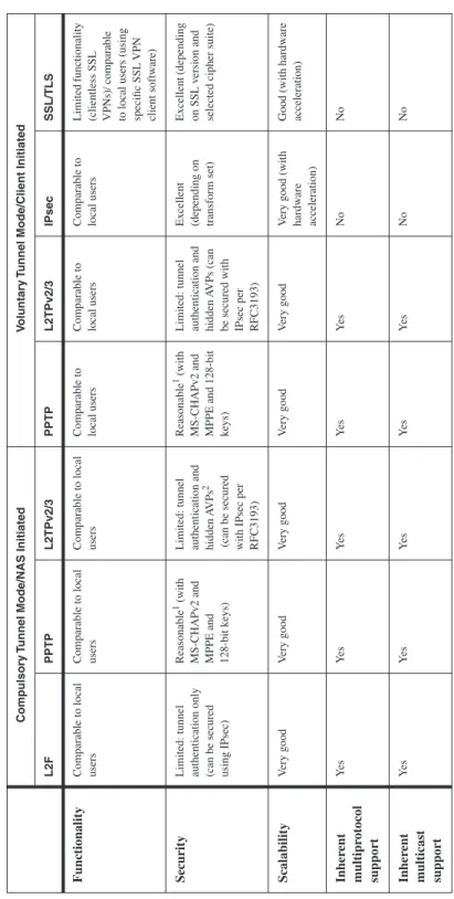
Table 1-2 shows how these considerations apply to the various remote access VPN technologies. Note that other important considerations, such as manageability and high availability, do not relate directly to the protocols and technologies themselves, but instead to particular vendor implementations and so are not described in this chapter.
Summary
This chapter introduced, explained, and compared VPN devices, protocols, technologies, and models.
VPNs may be service provider or customer provisioned and fall into one of two broad categories:
•
Site-to-site VPNs connect the geographically dispersed sites of an organization or organizations.•
Remote access VPNs connect mobile or home-based users to an organization’s resources at a central site.Review Questions
1 What type of connectivity is provided by site-to-site and remote access VPNs? 2 What protocols and technologies are commonly used to enable site-to-site VPNs? 3 What protocols are commonly used to enable remote access VPNs?
4 What are the two main categories of provider provisioned Layer 2 VPNs? 5 Name the two overall types of Layer 3 VPN.
Ta
b
le 1-2
Te
chnical Consider
ations for Remote
Access VPN T ec hnolo gies Compulsory T
unnel Mode/NAS Initiated
V
oluntary
T
unnel Mode/Client Initiated
L2F PPTP L2TPv2/3 PPTP L2TPv2/3 IPsec SSL/TLS Functionality
Comparable to local users Comparable to local users Comparable to local users Comparable to local users Comparable to local users Comparable to local users Limited functionality (clientless SSL VPNs)/ comparable to local users (using specific SSL
VPN
client softw
are)
Security
Limited: tunnel authentication only (can be secured using IPsec)
Reasonable
1 (with
MS-CHAPv2 and MPPE and 128-bit k
eys)
Limited: tunnel authentication and hidden A
VPs
2
(can be secured with IPsec per RFC3193)
Reasonable
1 (with
MS-CHAPv2 and MPPE and 128-bit keys) Limited: tunnel authentication and hidden A
VPs
(can
be secured with IPsec per RFC3193) Excellent (depending on transform set) Excellent (depending on SSL v
ersion and
selected cipher suite)
Scalability V ery good V ery good V ery good V ery good V ery good V
ery good (with
hardw
are
acceleration)
Good (with hardw
are acceleration) Inher ent multipr otocol support Ye s Ye s Ye s Y es Y es No No Inher ent multicast support Ye s Ye s Ye s Y es Y es No No
1PPTP security has been called into question—See http://www.schneier.com/paper-pptpv2.html and http://ciac.llnl.gov/ciac/bulleti
ns/i-087.shtml