Integrated Cleaner
Operators Manual
Integrated Cleaner
A40-039
Ultrasonics Corporation
41 Eagle Road Danbury, CT 06-813-1961
Integrated Cleaner
Introduction
1 Introduction
1.1
About This Manual
This manual contains instructions for installing, operating and maintaining Integrated Cleaners. Repair instructions are contained in a separate manual.
The following definitions apply in this manual:
Note: Inconvenience only if disregarded - no damage or personal injury. Caution: Equipment damage may occur, but not personal injury.
Warning:
Personal injury may occur - DO NOT DISREGARD.
PN indicates Part Number.Part(s) indicates your workpiece or component to be cleaned.
1.2
Manual Change Information
At Branson, we strive to maintain our position as the leader in ultrasonic cleaning and related technologies by continually improving circuits and components in our equipment. These improvements are incorporated as soon as they are developed and thoroughly tested. Change sheets are added to the manual periodically to reflect these improvements.
1.3
Unpacking and Handling
Use reasonable precautions when unpacking and handling your system. To avoid damage, use the shipping container when transporting the equipment.
Inspect all external controls and surfaces prior to setup to detect possible shipping damage. Report any damage at once to the carrier.
Note: The carrier is responsible for damage to equipment during shipment. If damage has occurred, notify the carrier immediately. Retain packing materials for inspection. The customer is responsible for filing the claim.
1.4
Warranty
IC Series Ultrasonic Cleaners, when used in accordance with manufacturer's instructions and under normal use, are guaranteed for one year after date of shipment. Within the period
guaranteed, Branson Ultrasonics will repair or replace free of charge, at its sole discretion, all parts that are defective because of material or workmanship.
Branson's liability, whether based on warranty, negligence or other cause, arising out of and/or incidental to sale, use or operation of the transducer elements, or any part thereof, shall not in any case exceed the cost of repair or replacement of the defective equipment, and such repair or replacement shall be the exclusive remedy of the purchaser, and in no case shall Branson be responsible for any and/or all consequential or incidental damages including without limitation, and/or all consequential damages arising out of commercial losses.
Integrated Cleaner
Warnings
1.1
Warnings
Warnings – Do's and Don'ts
Before using your ultrasonic cleaner, please read and thoroughly understand these warnings. Failure to follow them may result in serious personal injury or property damage.
To avoid electrical shock:
• Do keep the control panel and the area around the cleaner clean and dry - wipe up solution which spills over the tank brim. Water and high voltage can cause electrical shock.
• Don't operate the cleaner without proper grounding.
• Don't remove the grounding prong on the line cord plug.
• Don't disassemble your cleaner - high voltage inside the cleaner is dangerous.
• Don't immerse the cleaner in water.
To prevent personal and/or property damage:
• Use only non-flammable, non-combustible water-based solutions. Don't ever use alcohol, gasoline or flammable solutions. Do not use any solution that has a flash point. Using flammable or combustible solutions may result in a fire and severe burns.
• Always wear protective clothing; face shield and waterproof gloves and apron, when handling cleaning solutions. Thermal and chemical burns may result from splashed or spilled
chemicals.
• Always add chemicals to water. Never add water to chemicals. Adding water to chemicals may result in violent reactions that splash hot chemicals and can cause thermal or chemical burns.
• Never pick up a solution filled tank. Splashing may cause thermal or chemical burns.
• Do not overfill the tank. The tank may flood when large parts are inserted and cause thermal or chemical burns.
• Don't touch the stainless steel tank or cleaning solution - they may be hot.
• Don't place your fingers or hands into the tank while the cleaner is operating. Doing so may cause discomfort and possible skin irritation. Avoid contact with solutions and provide adequate ventilation.
• Don’t use solutions containing chlorine bleach.
To prevent damage to the cleaner:
• Do change your solution regularly.
• Don't ever use solutions that could attack stainless steel.
• Don't operate the cleaner dry.
• Don't place parts or containers directly on the bottom of the cleaning tank; use a wire basket or wire to suspend items. Failure to comply may cause transducer damage and will void your warranty.
• Don't allow the solution to drop more than 4 inches below the top with heat or ultrasonics on. Failure to comply may cause transducer and/or heater damage and will void your warranty.
• Do not use corrosive solutions such as bleaches, strong acids or powerful caustics in ultrasonic tanks. They may damage the tank. Using prohibited solutions will void the warranty.
Integrated Cleaner
Table of Contents
1.2
Table of Contents
Operators Manual ... 1
Integrated Cleaner... 1
1 Introduction ... 2
1.1 About This Manual ... 2
1.2 Manual Change Information... 2
1.3 Unpacking and Handling ... 2
1.4 Warranty ... 2
1.1 Warnings... 3
1.2 Table of Contents... 4
1.3 List of Figures... 5
1.4 General System Description ... 6
1.5 How Ultrasonics Works... 7
1.6 Ultrasonic Frequency Selection ... 7
1.7 Ultrasonic Damage to Parts ... 7
2 Specifications... 8
2.1 Cleaner Specifications ... 8
3 Component Locations... 11
3.1 Control Components... 11
3.1.1 POWER Switch ... 11
3.1.2 ON/OFF Switch ... 11
3.1.3 DIGITAL NUMBER DISPLAY ... 11
3.1.4 LED-DISPLAY ... 11
3.1.5 SET DISPLAY Switch ... 12
3.1.6 CLEAR DISPLAY Switch ... 12
3.1.7 SELECT OPTION Switch ... 12
3.2 Tank Components... 12
4 Operation ... 13
4.1 Location ... 13
4.2 Plumbing Connections... 13
4.3 Electrical Connections ... 13
4.4 Filling With Solution ... 14
4.4.1 Cleaning Solutions... 14
4.5 Solution Compatibility... 15
4.6 Filling the Tank... 15
4.7 Turning Power On ... 16
4.8 Turning Power Off... 16
4.9 Degassing... 16
4.10 Setting Degas Time... 16
4.11 Turning Degas On and Off ... 17
4.11.1 Interrupting Degas ... 17
4.11.2 Resetting time during degassing ... 17
4.12 Setting Ultrasonic Time ... 17
4.13 Turning Ultrasonics On and Off ... 17
4.13.1 Interrupting the ultrasonics ... 17
4.13.2 Resetting time during cleaning ... 17
4.14 Setting Tank Temperature ... 18
4.15 Turning Heat On and Off... 18
4.16 Displaying the Current Temperature ... 18
4.17 Loading Parts into the Cleaner... 18
4.17.1 Loading Baskets... 18
4.17.2 Suspending Parts... 19
Integrated Cleaner
Table of Contents
4.19 Draining The Cleaner ...19
5 Troubleshooting...20
5.1 Routine Inspection...20
5.2 Lubrication ...20
5.3 Troubleshooting...20
6 Assistance...22
6.1 Calling the Local Branson Representative ...22
6.2 Obtaining Replacement Parts ...22
1.3
List of Figures
Figure 1-1 Integrated Cleaner...6Figure 2-1 NEMA 6-15 Receptacle...8
Figure 2-2 IC1216 Dimensions ...9
Figure 2-3 IC1620 Dimensions ...10
Figure 3-1 IC Control Panel ...11
Figure 3-2 IC Components ...12
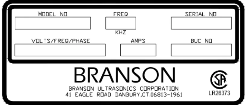
Figure 4-1 Specification Label ...13
Figure 4-2 Filling the Tank ...15
Figure 4-3 Cupping ...18
Integrated Cleaner
Introduction
1.4
General System Description
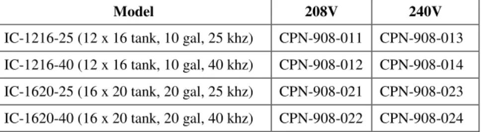
This line of ultrasonic cleaners includes four models and 2 voltages:
Model 208V 240V
IC-1216-25 (12 x 16 tank, 10 gal, 25 khz) CPN-908-011 CPN-908-013 IC-1216-40 (12 x 16 tank, 10 gal, 40 khz) CPN-908-012 CPN-908-014 IC-1620-25 (16 x 20 tank, 20 gal, 25 khz) CPN-908-021 CPN-908-023 IC-1620-40 (16 x 20 tank, 20 gal, 40 khz) CPN-908-022 CPN-908-024
Each model is manufactured from high quality stainless steel with integrated ultrasonic generator and electrical heating. Units are microprocessor controlled with an LED display for time and temperature functions.
Durable, industrial style 25 or 40 khz transducers provide high quality, consistent cleaning results. Each cleaner comes complete with a cover and a wire mesh basket.
Integrated Cleaner
Introduction
1.5
How Ultrasonics Works
Ultrasonic sound is sound transmitted at frequencies generally beyond the range of human hearing. In your ultrasonic cleaner, ultrasonic sound (sonics) is used for cleaning materials and parts. This is how it works:
As the sound waves from the transducer radiate through the solution in the tank, they cause alternating high and low pressures in the solution.
During the low pressure stage, millions of microscopic bubbles form and grow. This process is called CAVITATION.
During the high pressure stage, the bubbles collapse, or “implode”, releasing enormous amounts of energy. These implosions act like an army of tiny scrub brushes. They work in all directions, attacking every surface and invading all recesses and openings.
1.6
Ultrasonic Frequency Selection
The ultrasonic frequency was selected when the cleaner was purchased. 25 khz units are most effective when cleaning heavier parts with gross contamination. 40 khz units are better for precision cleaning of more delicate parts. Most applications can be cleaned at either frequency.
1.7
Ultrasonic Damage to Parts
Ultrasonic cleaners apply high intensity sound to parts and can damage very fine wires or thin films. Test susceptible parts for damage before cleaning production quantities.
Some semi-precious stones such as pearls, opals and some crystalline materials may be damaged by ultrasonics and should not be ultrasonically cleaned.
Integrated Cleaner
Component Locations
2 Specifications
2.1
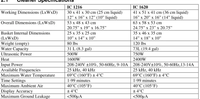
Cleaner Specifications
IC 1216 IC 1620
Working Dimensions (LxWxD) 30 x 41 x 30 cm (25 cm liquid)
12” x 16” x 12” (10” liquid) 41 x 51 x 41 cm (36 cm liquid) 16” x 20” x 16” (14” liquid) Overall Dimensions (LxWxD) 53 x 48 x 43 cm
20.75” x 19” x 16.75” 63 x 58 x 53 cm 24.75” x 23” x 20.75” Basket Internal Dimensions
(LxWxD) 25 x 35 x 25 cm 10” x 14” x 10” 35 x 46 x 35 cm 14” x 18” x 10”
Weight (empty) 80 lbs 120 lbs
Water Capacity 31 L (8.3 gal) 73L (19.4 gal)
Ultrasonic Power 500W 750W
Heat 1600W 2400W
Input Power 208-240V ±10%, 50-60Hz, 9-10A 208-240V±10%, 50-60Hz,13-14A
Available Frequencies 25 kHz, 40 kHz 25 kHz, 40 kHz
Maximum Water Temperature 69 C (160 F) ± 4 C 69 C (160 F) ± 4 C
Time Settings 1-99 minutes 1-99 minutes
Maximum Ambient Air 40 C (105 F) 40 C (105 F)
Display Accuracy ± 4 C ± 4 C
Maximum Ground Leakage <500µA <500µA
Materials of construction: Tank: 316-BA stainless steel Skirt: 304-4 stainless steel Cover: 304-4 stainless steel
Basket: 304 Stainless steel, #4 mesh, electropolished Control keypad: Lexan
Plug type: NEMA 6-15P Figure 2-1 NEMA 6-15 Receptacle
Integrated Cleaner
Component Locations
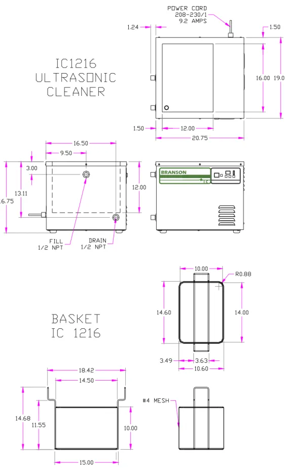
Figure 2-2 IC1216 DimensionsIntegrated Cleaner
Component Locations
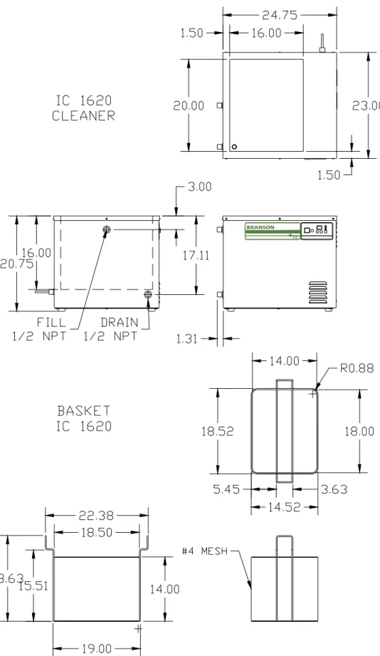
Figure 2-3 IC1620 DimensionsIntegrated Cleaner
Component Locations
3 Component Locations
Refer to Operating Instructions (Section 4) for full explanation of control operation.
3.1
Control Components
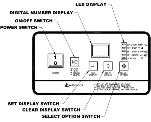
Figure 3-1 IC Control Panel
3.1.1 POWER Switch
Press “1” to turn power ON. Press “0” to turn power OFF.
3.1.2 ON/OFF Switch
Press to toggle selected functions ON and OFF.
3.1.3 DIGITAL NUMBER DISPLAY
Shows the temperature or time value or setpoint in accordance with the LED-DISPLAY.
3.1.4 LED-DISPLAY
Indicates whether Solution Temperature, Set Temperature, Sonics Set Time or Degas Set Time is active on the Digital Number Display. Indicates Heat ON/OFF status.
I/O
Integrated Cleaner
Component Locations
3.1.5 SET DISPLAY Switch
Use in conjunction with CLEAR DISPLAY, SELECT OPTION and LED-Display to change function settings.
3.1.6 CLEAR DISPLAY Switch
Press to clear the Digital Number Display when in the Set Temp, Set Sonics or Set Degas modes.
3.1.7 SELECT OPTION Switch
Press to toggle the LED-Display between Solution Temp, Set Temp, Set Sonics, Set Degas and Heat On.
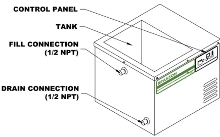
3.2
Tank Components
Figure 3-2 IC Components
Integrated Cleaner
Operation
4 Operation
4.1
Location
• Place the cleaner on a flat well drained surface.
• Allow at least 2 inches of space on the right side to exhaust cooling air.
Caution: Do not remove the feet from the cleaner or block air flow to the bottom panel. The cooling fan draws from the bottom and the ultrasonic generator will be damaged if air flow is not provided.
4.2
Plumbing Connections
• The cleaner is provided with a valve for the drain and a threaded cap on the fill fitting. The drain valve is shipped loose and must be installed prior to filling the cleaner.
• Install the ½ npt valve on the drain fitting. Connect this valve to drain in accordance with local wastewater regulations.
• If the fill fitting is connected to a public water supply, install a back flow preventer to ensure that cleaning solution does not get drawn into the water supply pipes.
4.3
Electrical Connections
• Check the specification label on the back of the cleaner for power requirements. The supply voltage must be within ±10% of the specification label voltage. Do not place the cleaner on a circuit that could become overloaded.
• Position the cleaner within easy reach of a standard grounded electrical outlet.
• Plug the cleaner into a grounded and fused receptacle.
Note: Do not use a ground fault protected (GFI) circuit. Normal leakage from the RF circuit will trip the protector. Ground leakage is less than 500µA.
Integrated Cleaner
Operation
4.4
Filling With Solution
4.4.1 Cleaning Solutions WARNING
Use only non-flammable, non-combustible water-based solutions. Do not use any solution that has a flash point. Using flammable or combustible solutions may result in a fire and severe burns. Caution: Do not use corrosive solutions such as bleaches, strong acids or powerful caustics in
ultrasonic tanks. They may damage the tank. Using prohibited solutions will void the warranty.
4.4.1.1 Solution types:
Water-based solutions are either slightly acidic or alkaline. They include detergents, soaps and industrial cleaners designed to remove specific soils.
• Acidic water-based solutions: remove rust, tarnish or scale. They range from mild solutions that remove tarnish, to concentrated inhibited acidic solutions that remove investment plaster, milk-stone, zinc oxide and rust from steel and cast iron as well as smut and heat-treat scale from hardened steel.
• Alkaline water-based solutions: include carbonates, silicates and caustics. These cause emulsifying action, which keeps soil from re-depositing on the cleaned surface, and improves cleaning action in hard water.
• Wetting Agents or Surfactants: reduce the surface tension of the water to allow the water to wet the part surface. Wetting agents increase ultrasonic activity.
Table 1 Solution Recommendations Market / Application Solution
Type Concentration in water Temp. (OF) pH Recommended Product
Buffing compounds – remove
tripoli, rouge, etc. Surfactant detergent 6 – 7 % 70 – 180 6.4 Branson BC Electronics – remove oil,
resin & rosin Strong alkaline Non-ionic 2 – 5 % 130 – 160 12.5 Branson EC General – remove light oil,
grease, dust & particulate Mild alkaline surfactant 10 – 12 % 70 – 180 12.1 Branson GP Jewelry – remove particulate,
soap, hand cream & oxide Mild alkaline surfactant 10 – 12 % 70 – 140 12.1 Branson JC Metal Mfg – remove oil &
grease from cutting & polishing
Strong alkaline
surfactant 7 – 10 % 120 – 160 12.4 Branson MC-3
Optical – remove dust, oil,
fingerprints, pitch & wax Mild alkaline Surfactant 7 – 10 % 130 – 180 9.8 Branson OC Metal Mfg – remove rust,
oxide & lime Phosphoric acid Citric acid or 6 – 7 % 70 – 120 3.8 Branson OR Stripping - heavy duty
cleaning, paint stripping, mold cleaning & de-scaling.
Strong caustic 3 – 6 % 160 – 180 13.0 Branson LRS
4.4.1.2 Solution Performance Factors
• Heat and cavitation: These increase the chemical activity of cleaning solutions. Some materials may be damaged by this stronger chemical action. When in doubt, test run samples of items to be cleaned.
Integrated Cleaner
Operation
• Solution amounts: Chemistry concentrations may vary. The amount of chemistry you use depends on the detergent and the type of soil to be removed. Follow instructions on the solution container.
• Solution Characteristics: Certain solutions cavitate better than others. Contact your local solution distributor for further information. 4.4.1.3 Solution Life
Change the cleaning solution periodically. Cleaning solutions become depleted through use and can become contaminated with suspended soil particles that coat the tank bottom, dampen the ultrasonic action and reduce cleaning efficiency.
4.5
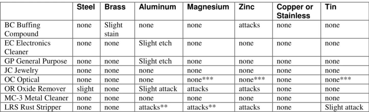
Solution Compatibility
Cleaning solutions may interact with materials and cause staining or etching. The following table is a guideline for use with Branson solutions. Consult the solution supplier for compatibility of non-Branson solutions.
Table 2 Solution Compatibility
Steel Brass Aluminum Magnesium Zinc Copper or Stainless Tin
BC Buffing
Compound none Slight stain none none attacks none none
EC Electronics
Cleaner none none Slight etch none none none none
GP General Purpose none none Slight etch none none none none
JC Jewelry none none none none none none none
OC Optical none none none none*** none*** none none***
OR Oxide Remover slight none Slight attack attacks attacks none none
MC-3 Metal Cleaner none none none none none none none
LRS Rust Stripper none none attacks** attacks** attacks none Slight attack * Slight etch on some aluminum alloys.
** Warning: Free hydrogen may be released if solution comes in contact with reactive metals. *** No effect if solution temperature is less than 140 F.
4.6
Filling the Tank
Fill the tank to 2 to 4 inches below the top with the selected pre-mixed solution. Allow for the volume of parts that may be cleaned.
Figure 4-2 Filling the Tank
Integrated Cleaner
Operation
WARNINGS
Use only non-flammable, non-combustible water-based solutions. Don't ever use alcohol, gasoline or flammable solutions. Do not use any solution that has a flash point. Using flammable or combustible solutions may result in a fire and severe burns. Always wear protective clothing; face shield and waterproof gloves and apron, when handling cleaning solutions. Thermal and chemical burns may result from splashed or spilled chemicals.
Always add chemicals to water. Never add water to chemicals. Adding water to chemicals may result in violent reactions that splash hot chemicals and can cause thermal or chemical burns.
Never pick up a solution filled tank. Splashing may cause thermal or chemical burns. Do not overfill the tank. The tank may flood when large parts are inserted and cause thermal or chemical burns.
Caution: Do not operate cleaner with the solution more than 4 inches below the top of the tank. The heaters on the sides of the tank will be damaged if operated when not completely covered by solution. The ultrasonics may be damaged if operated with no solution in the tank.
4.7
Turning Power On
Press the POWER switch at the “1” to turn power on. The cleaner will run through a three second self-test. The LED next to “SET DEGAS min” will light and the display will show the Degas set time (in minutes).
4.8
Turning Power Off
Press the POWER switch at the “0” to turn power off. All functions will turn off and the displays will be dark.
Note: Wait at least 10 seconds before turning POWER on after turning it off. If POWER is turned on too soon, the cleaner will restart in the same configuration as it had when it was turned off except that the control panel will be inoperative. Turn POWER off for 10 seconds to return to normal operation with all functions off.
4.9
Degassing
Fresh solutions and solutions that have been idle for more than 24 hours contain dissolved gases that reduce ultrasonic action. Operating the ultrasonics will remove these gases. Degas mode is provided as a convenience to operate the ultrasonics for the time required to degas.
4.10 Setting Degas Time
• Press the SELECT OPTION Switch until the LED next to “SET DEGAS min” lights. The current Degas setpoint is displayed in Digital Number Display. The default time is 5 minutes.
• Press CLEAR DISPLAY switch to set the time to 0.
Integrated Cleaner
Operation
4.11 Turning Degas On and Off
Note: Degas cannot be started if SONICS are on.
• Press the SELECT OPTION Switch until the LED next to “SET DEGAS min” lights. The current Degas setpoint is displayed in Digital Number Display.
• Press ON/OFF to toggle Degas on. Degas will operate for the set time. The display will count down the time remaining on the Digital Number Display.
• When the timer times out, the ultrasonics will turn off and the display will show the Degas set time.
4.11.1 Interrupting Degas
• Press ON/OFF to toggle Degas off before the set time has expired. The display will show the set time.
• If ON/OFF is pressed again, Degas will resume from where it was stopped and the display will show the time remaining.
4.11.2 Resetting time during degassing
• Press ON/OFF to toggle Degas off before the set time has expired.
• Press the SELECT OPTION switch until the “SET DEGAS min” LED lights.
• To increase time, press the SET DISPLAY switch until the desired setting is displayed.
• To decrease time, press the CLEAR DISPLAY switch then press the SET DISPLAY switch until the desired setting is displayed.
4.12 Setting Ultrasonic Time
• Press the SELECT OPTION Switch until the LED next to “SET SONICS min” lights. The current setpoint is displayed in Digital Number Display.
• Press CLEAR DISPLAY switch to set the time to 0.
• Repeatedly press SET DISPLAY to set the desired Sonics time between 01 and 99 minutes.
4.13 Turning Ultrasonics On and Off
Note: Ultrasonics cannot be started if Degas is on.
• Press the SELECT OPTION Switch until the LED next to “SET SONICS min” lights. The current setpoint is displayed in Digital Number Display.
• Press ON/OFF to toggle Sonics on. The ultrasonics will operate for the set time. The display will count down the time remaining on the Digital Number Display.
• When the timer times out, the ultrasonics will turn off and the display will show the sonics set time.
4.13.1 Interrupting the ultrasonics
• Press ON/OFF to toggle sonics off before the set time has expired. The display will show the set time.
• If ON/OFF is pressed again, the sonics function will resume from where it was stopped and the display will show the time remaining.
4.13.2 Resetting time during cleaning
• Press ON/OFF to toggle sonics off before the set time has expired.
• Press the SELECT OPTION switch until the “SET SONICS min” LED lights.
• To increase time, press the SET DISPLAY switch until the desired setting is displayed.
Integrated Cleaner
Operation
• To decrease time, press the CLEAR DISPLAY switch then press the SET DISPLAY switch until the desired setting is displayed
4.14 Setting Tank Temperature
Heat increases the chemical activity of cleaning solutions.
• Press the SELECT OPTION Switch until the LED next to “SET TEMP oC” lights. The current setpoint is displayed in Digital Number Display (in degrees C).
• Press CLEAR DISPLAY switch to set the temperature to less than the current setpoint. “00” will be displayed.
• Repeatedly press SET DISPLAY until the desired temperature between 01 and 69 C is displayed.
4.15 Turning Heat On and Off
• Press the SELECT OPTION Switch until the LED next to “SET TEMP oC” lights. The set temperature in C is displayed in Digital Number Display.
• Press ON/OFF to toggle Heat on or off. The LED next to “HEAT ON” will light.
• Wait until the solution reaches the desired operating temperature. The tank will heat more rapidly if the tank is covered when no actually cleaning parts. The tank will heat more rapidly if the ultrasonics are on.
• Operating with the cover on will cause the tank to heat faster and will allow operation at higher temperatures.
Note: The ultrasonics may heat the solution beyond the temperature set point. If this happens, turn the cleaner off and allow the solution to cool or replace some of the warm solution with cold solution.
4.16 Displaying the Current Temperature
Press the SELECT OPTION Switch until the LED next to “SOLUTION TEMP oC” lights. The current temperature is displayed in Digital Number Display (in degrees C). The cleaning cycle will continue during this process.
4.17 Loading Parts into the Cleaner
Caution: Do not place parts or containers directly on the bottom of the cleaning tank. Contact with parts or baskets may damage the tank or the ultrasonic elements. Use a wire basket or wire to suspend items.
4.17.1 Loading Baskets
• Place items in the wire basket so that they do not cup liquids. Cupping liquids will cause poor drying and staining.
Figure 4-3 Cupping
Integrated Cleaner
Operation
• Place items in the baskets so that they do not trap air when immersed. Trapped air will prevent the solution from contacting the soils. No cleaning will take place in the areas not exposed to solution.
Figure 4-4 Trapped Air
• Do not overload baskets. Overloading will cause inconsistent cleaning.
• Use fixtures or racks to orient and separate parts and to prevent nesting. Nesting will cause inconsistent cleaning and staining where the parts contact each other.
4.17.2 Suspending Parts
Suspend individual parts from wires so that they do not contact the tank walls or bottom. Rods may be placed across the top of the tank to support the wires.
4.18 Cleaning the Parts
• Slowly lower the basket into the tank. Do not stir.
• Press the SELECT OPTION switch until the “SET SONICS min” LED is lighted.
• Press the ON/OFF switch to toggle the ultrasonics on. The Digital Number Display will count down the time remaining. The ultrasonics will turn off when time has elapsed and the display will show the set time.
• Slowly remove the basket from the tank. Allow the parts to drip into the tank.
• Rinse the parts with clean water and dry, if necessary.
4.19 Draining The Cleaner
Open the drain valve and allow the tank to drain. Close the drain valve.
Integrated Cleaner
Troubleshooting
5 Troubleshooting
5.1
Routine Inspection
Check the cleaner for signs of leaks or damage.
5.2
Lubrication
No lubrication is required.
5.3
Troubleshooting
WARNING
High voltage inside - dangerous shock hazard. DO NOT attempt to disassemble or repair the cleaner.
Problem Cause What to do
Cleaner will not start. Cleaner not plugged in
pro-perly. Plug into functioning electrical outlet. POWER switch not ON. Press power switch “1”. Malfunctioning start button. Call Branson Commercial
Products Department 800-731-9162.
Blown fuse. Call Branson Commercial
Products Department 800-731-9162.
Cleaner operates but does not heat solution.
HEAT not set properly. See “Operating your IC cleaner”.
Malfunctioning membrane. Call Branson Commercial Products Department 800-731-9162.
Malfunctioning heater. Call Branson Commercial Products Department 800-731-9162.
Cleaner operates but does not maintain set temperature.
Malfunctioning heater or
sensor components. Call Branson Commercial Products Department 800-731-9162.
Integrated Cleaner
Troubleshooting
Problem Cause What to do
Cleaner operates but display does not function.
Interrupted calibration se-quence.
Malfunctioning timer board.
Press SET DISPLAY. Call Branson Commercial Products Department 800-731-9162.
Decreased ultrasonic
activity. Solution is not degassed. Make sure that tank was filled with warm tap water plus cleaning solution and has run 5-10 minutes.
Solution is spent. Change solution. Solution level is incorrect for
load. Adjust solution to operating level line with load. Tank bottom is covered with
soil particles. Empty, then clean tank with warm water. Wipe with a nonabrasive cloth.
Using deionized water in the
tank. Deionized water does not cavitate as actively as soapy tap water.
Integrated Cleaner
Assistance
6 Assistance
6.1
Calling the Local Branson Representative
If you have a problem call the Branson Commercial Products Department at 800-732-9262. Before you call, take the following steps:
1. Have this manual with you.
2. Know how your system has been set up and equipped, including any software versions in 3. your system.
4. Describe the problem.
5. List the steps you have already taken.