Deploying 10 Gigabit Ethernet on VMware vSphere 4.0 with
Cisco Nexus 1000V and VMware vNetwork Standard and
Distributed Switches - Version 1.0
Table of Contents
Introduction... 3
Design Goals... 3
VMware ESX and ESXi Network Adapter Configurations... 3
Traffic Types in a VMware vSphere 4.0 Environment... 3
Cisco Nexus 1000V 10 Gigabit Ethernet Network Design... 4
Design Choices: MAC Pinning or Virtual PortChannel?... 4
vPC... 5
MAC Pinning... 6
Other Cisco Nexus 1000V Design Considerations... 6
Traffic Isolation and Prioritization... 6
Rate Limiting... 6
MAC Pinning: Detailed Design... 7
Configuration Information for MAC Pinning Design Example... 7
Example of VLAN Mapping... 7
Server Uplink Connections... 7
Cisco Nexus 5000 Configuration for MAC Pinning... 8
N5K-1 Configuration... 8
N5K-2 Configuration... 8
Cisco Nexus 1000V Configuration for MAC Pinning... 9
Cisco Nexus 1000V Configuration of Cisco NX-OS Software Statements for MAC Pinning... 9
Status Display of Uplink Port Profile on Cisco Nexus 1000V with MAC Pinning... 9
Example of a Port Profile for the Service Console... 10
vPC: Detailed Design... 11
PortChannel Technology... 11
Traffic Distribution in a PortChannel... 11
vPC Configuration Overview... 11
Configuration Information for the vPC Design Example... 12
Example of VLAN Mapping... 12
Cisco Nexus 5000 Series Interconnection for vPC... 12
Server Connections... 12
Cisco Nexus 5000 Series Configuration for vPC... 13
N5K-1 Configuration... 13
N5K-2 Configuration... 15
Cisco Nexus 1000V Switch Configuration for vPC... 17
Cisco Nexus 1000V Configuration Statements for vPC... 17
Cisco Nexus 1000V Status Listing for vPC-Configured Uplinks... 17
Advanced Configuration Options for Cisco Nexus 1000V... 19
Rate Limiting... 19
VMware vSS and vDS Configuration... 21
Teaming Policy Options... 21
Teaming Policy for Two 10 Gigabit Ethernet Interfaces... 21
Other Teaming Policy Variations... 23
Advanced VMware vSS and vDS Options: Using Traffic Shaping to Control and Limit Traffic.... 24
Cisco Nexus 5000 Series Configuration for VMware vDS and vSS... 25
N5K-1 Configuration... 25
N5K-2 Configuration... 25
Conclusion... 25
Introduction
This document provides design guidance for implementing 10 Gigabit Ethernet networking with VMware vSphere 4.0 (including VMware ESXi 4.0 and ESX 4.0 and associated updates) in a Cisco® network environment. The document covers considerations, approaches, and best practices for configuration of the following:
● Virtual network based on the Cisco Nexus® 1000V Switch, VMware vNetwork Standard
Switch (vSS), and VMware vNetwork Distributed Switch (vDS).
● Physical network (access and distribution layers) based on Cisco Nexus 5000 Series Switches at the access layer.
● Some additional information about advanced configuration using rate limiting is provided later in this document.
Design Goals
The configurations that follow are designed according to the following design goals:
● Availability: The design should be capable of recovery from any single points of failure in the network outside the VMware ESX or ESXi server. Traffic should continue to flow if a single access or distribution switch, cable, or network interface fails.
● Isolation: Each traffic type should be logically isolated from every other traffic type.
● Performance: The design should provide the capability to impose limits on some traffic types to reduce the effects on other traffic types.
VMware ESX and ESXi Network Adapter Configurations
In 10 Gigabit Ethernet environments, the most common configurations are as follows:● Two 10 Gigabit Ethernet interfaces (converged network adapter [CNA], network interface
card [NIC], or LAN on motherboard [LOM]).
● Two 10 Gigabit Ethernet interfaces (CNA or NIC) plus two Gigabit Ethernet LOM ports. Although more adapters and configurations are possible, this guide focuses on the most common design scenario, with all traffic is converged to two 10 Gigabit Ethernet interfaces. The configuration using an additional two Gigabit Ethernet interfaces for management is a valid design for all virtual switch alternatives and is discussed in the Cisco Nexus 1000V Switch section as a design variant.
Traffic Types in a VMware vSphere 4.0 Environment
A VMware vSphere 4.0 environment involves the following traffic types:● Management: Management traffic goes through the vswif interface on VMware ESX or the vmkernel management interface on VMware ESXi. This is the port used for all management and configuration and is the port by which VMware ESX or ESXi communicates with VMware vCenter Server. This port generally has very low network utilization, but it should always be available and isolated from other traffic types through a management VLAN.
● VMware VMotion: The vmkernel port is used for migrating a running virtual machine from one
VMware ESX or ESXi host to another. With VMware ESX or ESXi 4.0, a single VMware VMotion migration through this port can use up to approximately 2.6 Gbps of network
bandwidth, with up to two VMware VMotion migrations running concurrently. This traffic typically is implemented on a separate VLAN specific to VMware VMotion, with no outside communication required.
● Fault-tolerant logging: The vmkernel port for fault-tolerant logging is used to transfer the input
network I/O for the fault-tolerant virtual machine plus the read disk traffic to the secondary fault-tolerant virtual machine. Traffic will vary according to the network and storage behavior of the application. End-to-end latency between the fault-tolerant virtual machines should be less than 1 millisecond (ms). This traffic typically is implemented on a separate VLAN specific to fault-tolerant logging, with no outside communication required.
● Small Computer Interface over IP (iSCSI): The vmkernel port is used for the software iSCSI initiator in VMware ESX or ESXi. In VMware ESX or ESXi 4.0, two iSCSI vmkernel ports can be bonded to allow iSCSI traffic over both physical network interfaces. Traffic varies according to I/O. This traffic typically is implemented on an iSCSI-specific VLAN common to iSCSI initiators and targets, although targets may reside on another VLAN accessible through a Layer 3 gateway.
● Network File System (NFS): The vmkernel port is used for communication with NFS files in VMware ESX or ESXi. Traffic varies according to I/O. This traffic typically is implemented on an NFS-specific VLAN, although filers may reside on another VLAN accessible through a Layer 3 gateway.
● Virtual Machines: Guest virtual machines will vary in number and may be distributed over more than one VLAN and be subject to different policies defined in port profiles and distributed virtual port groups.
Cisco Nexus 1000V 10 Gigabit Ethernet Network Design
This section describes two network design approaches when implementing the Cisco Nexus 1000V virtual switch with 10 Gigabit Ethernet network adapters in a VMware vSphere 4.0 environment.
Design Choices: MAC Pinning or Virtual PortChannel?
Network architects can use two different approaches for incorporating the Cisco Nexus 1000V into the data center network environment: virtual PortChannel (vPC) and MAC pinning. Both design approaches provide protection against single-link and physical-switch failures, but they differ in the way that the virtual and physical switches are coupled and the way that the VMware ESX or ESXi server traffic is distributed over the 10 Gigabit Ethernet links.
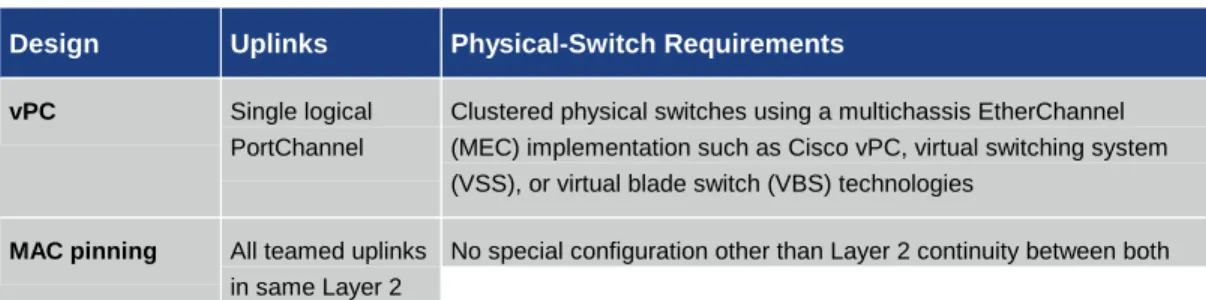
Table 1 summarizes the differences and design approaches for Cisco Nexus 1000V implementations.
Table 1. Differences Between vPC and MAC Pinning
Design Uplinks Physical-Switch Requirements
vPC Single logical
PortChannel
Clustered physical switches using a multichassis EtherChannel (MEC) implementation such as Cisco vPC, virtual switching system (VSS), or virtual blade switch (VBS) technologies
Design Uplinks Physical-Switch Requirements
domain switches on all VLANs trunked to the VMware ESX or ESXi server
vPC is the recommended approach when vPC or clustered physical switches are available at the physical access layer. MAC pinning should be chosen when these options are not available.
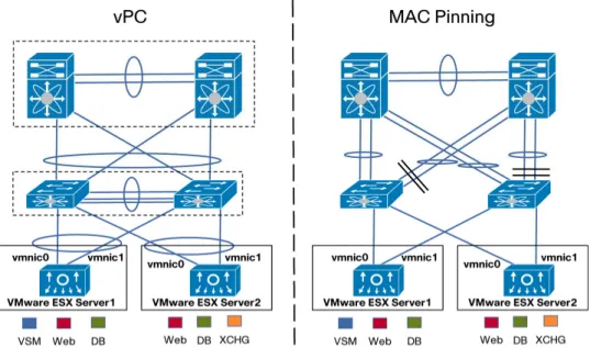
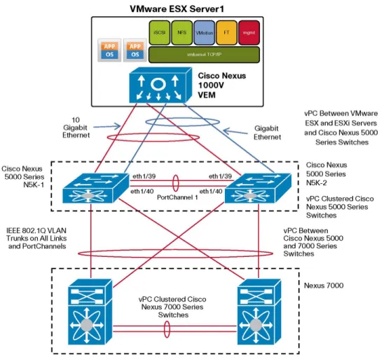
Figure 1 compares vPC and MAC pinning. Detailed designs for vPC and MAC pinning are described in the sections that follow.
Figure 1. Topology Comparison of vPC and MAC Pinning
Note: With vPC from the host to the access layer and then vPC up to the aggregation layer or core, the deployment of a virtualized environment with VMware provides a fully redundant and highly utilized infrastructure.
vPC
In a vPC design, the 10 Gigabit Ethernet uplinks from the Cisco Nexus 1000V are aggregated in a single logical link (PortChannel) to the two adjacent physical switches. The adjacent physical switches require vPC capability (for example, a Cisco Nexus 5000 Series Switch), in which they appear as a single logical switch distributed over two physical chassis. vPC allows the aggregation of two or more physical server ports to connect to a pair of Cisco Nexus 5000 or 7000 switches to make the connection look like one logical upstream switch. This approach provides better bandwidth utilization and redundancy. Cisco Catalyst® 6500 VSS 1440 and Cisco Catalyst 3100 Switch VBS technologies provide functions similar to vPC and can be used in a vPC design with the Cisco Nexus 1000V.
MAC Pinning
In a MAC pinning design, the 10 Gigabit Ethernet uplinks from the Cisco Nexus 1000V are treated as stand-alone links. In a two 10 Gigabit Ethernet uplink scenario, each 10 Gigabit Ethernet interface is connected to a separate physical switch with Layer 2 continuity on all IEEE 802.1Q trunked VLANs between the two switches. Virtual Ethernet ports supporting virtual machines, and vmkernel ports are allocated in a round-robin fashion over the available 10 Gigabit Ethernet uplinks. Each MAC address is pinned to one of the uplinks until a failover event occurs. MAC pinning does not rely on any protocol to distinguish the different upstream switches, making the deployment independent of any hardware or design. This independence enables consistent and easy
deployment of the Cisco Nexus 1000V, and it is the preferred method for deploying the Cisco Nexus 1000V when the upstream switches cannot be clustered using Cisco vPC, VSS, or VBS
technologies.
Other Cisco Nexus 1000V Design Considerations
The Cisco Nexus 1000V has a rich set of features, most of which are common to, and can be used with, both vPC and MAC pinning designs. Quality of service (QoS), access control lists (ACLs), and rate limiting all can be used to apply special treatment to particular traffic types.
Traffic Isolation and Prioritization
The Cisco Nexus 1000V can provide consistent traffic isolation for the various VMware traffic types using port profiles. Port profiles map to distributed virtual port groups on the VMware vCenter Server. Guest virtual machines and vmkernel ports are then allocated to these distributed virtual port groups (port profiles) by the server administrator.
Within the port profiles, parameters can be set that apply to a specific traffic type such as
management, IP storage, VMware VMotion, or virtual machine traffic. These parameters cover such details as port security, VLAN, and ACLs. Policy maps for QoS treatment can be set on a per-port-profile basis to enable policing and prioritization of the individual traffic types within the physical network.
More information about configuring QoS with the Cisco Nexus 1000V can be found in the Cisco Nexus 1000V Quality-of-Service Configuration Guide.
http://www.cisco.com/en/US/docs/switches/datacenter/nexus1000/sw/4_0_4_s_v_1_2/qos/configura tion/guide/n1000v_qos_5statistics.html.
Rate Limiting
When deploying 10 Gigabit Ethernet interfaces in a virtualized environment and allowing all the various traffic traversing the physical interface, it is critical that any one type of traffic does not overconsume the bandwidth. The Cisco Nexus 1000V provides the capability to rate limit the ingress or egress bandwidth down to the virtual Ethernet port level. In the Cisco Nexus 1000V, this
capability can be applied as part of a port profile for a particular type of traffic (for example, VMware VMotion) and is automatically applied to all virtual Ethernet interfaces inherited from that port profile. This capability can also be applied on a per-virtual Ethernet interface. An example of this
MAC Pinning: Detailed Design
This section describes how to design and configure MAC pinning for the Cisco Nexus 1000V. Use MAC pinning when you have two isolated (nonclustered) physical switches that share and provide Layer 2 continuity on all trunked VLANs.
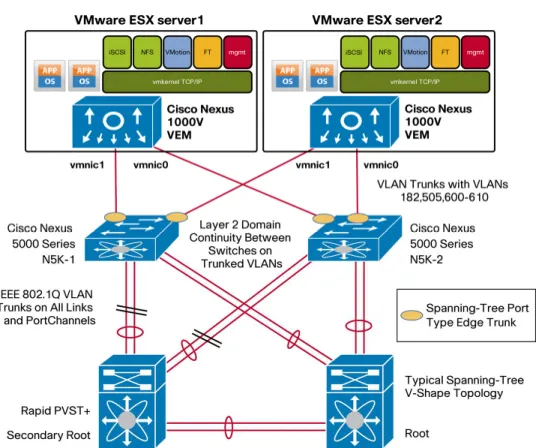
Configuration Information for MAC Pinning Design Example
The VLAN map and physical NIC configuration used in the MAC pinning design example is shown in Figure 2 and summarized here.
Example of VLAN Mapping
Management (service console) VLAN: 182
iSCSI VLAN: 505
Control and packet VLAN: 600
VMware VMotion VLAN: 601
Virtual machine data VLANs: 602 through 610
Server Uplink Connections
VMware ESX Server 1: Cisco Nexus 5000 Series Switch 1 (N5K-1) interface Ethernet 1/1, N5K-2 interface Ethernet 1/1.
VMware ESX Server 2: N5K-1 interface Ethernet 1/5, N5K-2 interface Ethernet 1/5.
Cisco Nexus 5000 Configuration for MAC Pinning
The following code is an excerpt of the Cisco NX-OS Software switch configurations for the two Cisco Nexus 5000 Series Switches configured for MAC pinning. The listing shows the switch-port configuration for the switch interfaces connecting to the VMware ESX or ESXi server.
N5K-1 Configuration
n5k-1# show running-config interface ethernet 1/1, ethernet 1/5 version 4.1(3)N2(1a)
interface Ethernet1/1 switchport mode trunk
switchport trunk native vlan 182
switchport trunk allowed vlan 182,505,600-610 spanning-tree port type edge trunk
interface Ethernet1/5 switchport mode trunk
switchport trunk native vlan 182
switchport trunk allowed vlan 182,505,600-610 spanning-tree port type edge trunk
N5K-2 Configuration
n5k-2# show running-config interface ethernet 1/1, ethernet 1/5 version 4.1(3)N2(1a)
interface Ethernet1/1 switchport mode trunk
switchport trunk native vlan 182
switchport trunk allowed vlan 182,505,600-610 spanning-tree port type edge trunk
interface Ethernet1/5 switchport mode trunk
switchport trunk native vlan 182
switchport trunk allowed vlan 182,505,600-610 spanning-tree port type edge trunk
Note: These are server-facing ports, so set the spanning-tree port type to edge trunk on the Cisco Nexus 5000 Series Switches. This setting is similar to spanning-tree portfast trunk on Cisco IOS® Software.
Cisco Nexus 1000V Configuration for MAC Pinning
Cisco Nexus 1000V Configuration of Cisco NX-OS Software Statements for MAC Pinning VSM# show running-config port-profile system-uplink
version 4.0(4)SV1(3)
port-profile type ethernet system-uplink vmware port-group
switchport mode trunk
switchport trunk native vlan 182
switchport trunk allowed vlan 1,182,505,600-610 channel-group auto mode on mac-pinning
no shutdown
system vlan 182,505,600 state enabled
Status Display of Uplink Port Profile on Cisco Nexus 1000V with MAC Pinning VSM# show port-profile name system-uplink
port-profile system-uplink description:
type: ethernet status: enabled
capability l3control: no pinning control-vlan: - pinning packet-vlan: - system vlans: 182,505,600 port-group: system-uplink max ports: -
inherit:
config attributes: switchport mode trunk
switchport trunk native vlan 182
switchport trunk allowed vlan 1,182,505,600-610 channel-group auto mode on mac-pinning
no shutdown
evaluated config attributes: switchport mode trunk
switchport trunk native vlan 182
switchport trunk allowed vlan 1,182,505,600-610 channel-group auto mode on mac-pinning
assigned interfaces: port-channel1 port-channel2
Ethernet3/3 (member of port-channel1) Ethernet3/4 (member of port-channel1) Ethernet4/5 (member of port-channel2) Ethernet4/6 (member of port-channel2)
Note: In the system-uplink port profile, list VLANs required at startup (and prior to virtual supervisor module (VSM) communication) as system VLANs: for example, control, packet, management (these are mandatory), and iSCSI (if applicable).
Note: The channel-group auto mode on mac-pinning statement configures the end-host PortChannel for MAC pinning. This setting automatically creates a PortChannel when the two 10 Gigabit Ethernet interfaces are placed under Cisco Nexus 1000V control.
Example of a Port Profile for the Service Console
VSM# show port-profile name service-console port-profile service-console
description: type: vethernet status: enabled
capability l3control: no pinning control-vlan: - pinning packet-vlan: - system vlans: none
port-group: service-console max ports: 32
inherit:
config attributes:
switchport mode access switchport access vlan 182 no shutdown
evaluated config attributes: switchport mode access switchport access vlan 182 no shutdown
assigned interfaces: Vethernet1
vPC: Detailed Design
This section presents a detailed design example for a Cisco Nexus 1000V and a pair of adjacent Cisco Nexus 5000 Series Switches clustered for vPC.
PortChannel Technology
A PortChannel on the Cisco Nexus 1000V implements the standards-based IEEE 802.3ad or 802.1AX link aggregation protocol that incorporates the Link Aggregation Control Protocol (LACP) for automatic negotiation. The adjacent physical switches must support the same protocol. A MEC capability such as vPC, VSS, or VBS is required on the adjacent physical switches to enable the PortChannel to span both physical switches and still maintain availability for the VMware ESX or ESXi 4.0 host should one switch fail or lose connectivity.
When PortChannels are spread across more than one physical switch, the switches are deemed to be clustered. Examples of clustered switching technology include the Cisco Catalyst 6500 Series and the Cisco Catalyst 3100 blade switch, which uses VSS. vPCs are available on the Cisco Nexus 5000 and 7000 Series Switches. This clustering is transparent to the Cisco Nexus 1000V Switch. When the upstream switches are clustered, the Cisco Nexus 1000V Series Switch should be configured to use an LACP PortChannel with the two 10 Gigabit Ethernet uplinks defined by one port profile.
Traffic Distribution in a PortChannel
Traffic is distributed over the available links (two 10 Gigabit Ethernet links in this case) according to the load-balancing algorithm configured at each end of the PortChannel. The algorithm determines the link based on a hash of various fields in the headers of each packet. The source-dest-ip-port specification hashes the source and destination IP addresses and TCP ports and provides the finest granularity. Note that all packets for a flow between a single source and destination IP address and port will use the same physical links, and that different load-balancing algorithms can be selected at each end of the PortChannel.
Seventeen load-balancing algorithms are available on the Cisco Nexus 1000V. Refer to Cisco Nexus 1000V Series Switches Deployment Guide Version 2 at
http://www.cisco.com/en/US/prod/collateral/switches/ps9441/ps9902/guide_c07-556626.html for a full discussion of the options.
vPC Configuration Overview
The configuration examples that follow show the VMware ESX and ESXi 4.0 hosts equipped with a Cisco Nexus 1000V connected through two 10 Gigabit Ethernet links to a clustered pair of Cisco Nexus 5000 Series Switches configured for vPC.
When configuring the vPC PortChannels between the Cisco Nexus 1000V and Cisco Nexus 5000 Series Switches, set the LACP negotiation parameters as follows:
● Cisco Nexus 1000V: Channel group auto mode active ● Cisco Nexus 5000 Series: Channel group mode active
For a full explanation and discussion of network design with vPC, refer to Cisco NX-OS Software Virtual PortChannel: Fundamental Concepts at
http://www.cisco.com/en/US/prod/collateral/switches/ps9441/ps9670/C07-572835-00_NX-OS_vPC_DG.pdf.
Configuration Information for the vPC Design Example
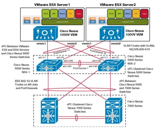
The VLAN map and physical NIC configuration used in the vPC design example is as shown in Figure 3 and summarized here.
Example of VLAN Mapping
Management (service console) VLAN: 182
iSCSI VLAN: 505
Control and packet VLAN: 600
VMware VMotion VLAN: 601
Virtual machine data VLANs: 602 through 610
Cisco Nexus 5000 Series Interconnection for vPC
N5K-1 interface Ethernet 1/39 is connected to N5K-2 interface Ethernet 1/39.
N5K-1 interface Ethernet 1/40 is connected to N5K-2 interface Ethernet 1/40.
Preceding two ports are used to create a PortChannel between the two Cisco Nexus 5000 Series Switches.
Server Connections
VMware ESX Server 1: N5K-1 interface Ethernet 1/1, N5K-2 interface Ethernet 1/1.
Figure 3. Cisco Nexus 1000V Connectivity with vPC
Cisco Nexus 5000 Series Configuration for vPC
The following code is an excerpt of the Cisco NX-OS Software switch configurations for the
clustered Cisco Nexus 5000 Series Switches configured for vPC. The listing shows the PortChannel configuration in addition to the corresponding switch-port configuration for the switch interfaces connecting to the VMware ESX or ESXi server.
Note: Make sure that feature lacp and feature vpc are enabled on both Cisco Nexus 5000 Series Switches.
N5K-1 Configuration !
! create portchannel1 to interconnect n5k switches on eth1/39-40
!
interface port-channel1 switchport mode trunk
switchport trunk allowed vlan 1,182,505,600-610 vpc peer-link
spanning-tree port type network speed 10000
interface Ethernet1/39 switchport mode trunk
switchport trunk allowed vlan 1,182,505,600-610 channel-group 1
interface Ethernet1/40 switchport mode trunk
switchport trunk allowed vlan 1,182,505,600-610 channel-group 1
!
! portchannel 11 connects to ESX/ESXi server 1 ! using eth1/1 on both switches
!
interface port-channel11 switchport mode trunk
switchport trunk native vlan 182
switchport trunk allowed vlan 182,505,600-610 vpc 11
spanning-tree port type edge trunk speed 10000
interface Ethernet1/1 switchport mode trunk
switchport trunk native vlan 182
switchport trunk allowed vlan 182,505,600-610 spanning-tree port type edge trunk
channel-group 11 mode active
!
! portchannel 12 connects to ESX/ESXi server 2 ! using eth1/5 on both switches
!
interface port-channel12 switchport mode trunk
switchport trunk native vlan 182
spanning-tree port type edge trunk speed 10000
interface Ethernet1/5 switchport mode trunk
switchport trunk native vlan 182
switchport trunk allowed vlan 182,505,600-610 spanning-tree port type edge trunk
channel-group 12 mode active N5K-2 Configuration
!
! create portchannel1 to interconnect n5k switches on eth1/39-40
!
interface port-channel1 switchport mode trunk
switchport trunk allowed vlan 1,182,505,600-610 vpc peer-link
spanning-tree port type network speed 10000
interface Ethernet1/39 switchport mode trunk
switchport trunk allowed vlan 1,182,505,600-610 channel-group 1
interface Ethernet1/40 switchport mode trunk
switchport trunk allowed vlan 1,182,505,600-610 channel-group 1
!
! portchannel 11 connects to ESX/ESXi server 1 ! using eth1/1 on both switches
!
interface port-channel11 switchport mode trunk
switchport trunk native vlan 182
vpc 11
spanning-tree port type edge trunk speed 10000
interface Ethernet1/1 switchport mode trunk
switchport trunk native vlan 182
switchport trunk allowed vlan 182,505,600-610 spanning-tree port type edge trunk
channel-group 11 mode active
!
! portchannel 12 connects to ESX/ESXi server 2 ! using eth1/5 on both switches
!
interface port-channel12 switchport mode trunk
switchport trunk native vlan 182
switchport trunk allowed vlan 182,505,600-610 vpc 12
spanning-tree port type edge trunk speed 10000
interface Ethernet1/5 switchport mode trunk
switchport trunk native vlan 182
switchport trunk allowed vlan 182,505,600-610 spanning-tree port type edge trunk
channel-group 12 mode active
Note: Since these are server ports, it is recommended that you set the spanning-tree port type to edge trunk on the Cisco Nexus 5000 Series Switches. This setting is similar to portfast on Cisco IOS Software.
Cisco Nexus 1000V Switch Configuration for vPC
The following listing details the recommended design for a Cisco Nexus 1000V using vPC on the two 10 Gigabit Ethernet uplinks. LACP is used as the method for building the PortChannel between the Cisco Nexus 1000V virtual switch and the Cisco Nexus 5000 Series physical switches.
version 4.0(4)SV1(3)
port-profile type ethernet system-uplink vmware port-group
switchport mode trunk
switchport trunk native vlan 182 switchport trunk allowed vlan all channel-group auto mode active no shutdown
system vlan 182,505,600 state enabled
Cisco Nexus 1000V Status Listing for vPC-Configured Uplinks VSM# show port-profile name system-uplink port-profile system-uplink
description: type: ethernet status: enabled
capability l3control: no pinning control-vlan: - pinning packet-vlan: - system vlans: 182,505,600 port-group: system-uplink max ports: -
inherit:
config attributes: switchport mode trunk
switchport trunk native vlan 182
switchport trunk allowed vlan 1,182,505,600-610 channel-group auto mode active
no shutdown
evaluated config attributes: switchport mode trunk
switchport trunk native vlan 182
switchport trunk allowed vlan 1,182,505,600-610 channel-group auto mode active
no shutdown
assigned interfaces: port-channel1 port-channel2
Ethernet3/3 (member of port-channel1) Ethernet3/4 (member of port-channel1) Ethernet4/5 (member of port-channel2) Ethernet4/6 (member of port-channel2)
VSM# show port-channel summary
Flags: D - Down P - Up in port-channel (members) I - Individual H - Hot-standby (LACP only) s - Suspended r - Module-removed
S - Switched R - Routed U - Up (port-channel)
--- Group Port- Type Protocol Member Ports
Channel
--- 1 Po1(SU) Eth LACP Eth3/3(P) Eth3/4(P) 2 Po2(SU) Eth LACP Eth4/5(P) Eth4/6(P)
Note: With vPC configuration, the system-uplink port profile should have the channel-group mode set to active to permit LACP to form the PortChannel with the adjacent Cisco Nexus 5000 Series Switches.
Note: Other port-profile configurations remain the same and are common to both MAC pinning and vPC.
Design Variation for Two Gigabit Ethernet and Two 10 Gigabit
Ethernet Interfaces
The example in Figure 4 illustrates a variation of the Cisco Nexus 1000V vPC design in which two Gigabit Ethernet LOM interfaces are used in addition to two 10 Gigabit Ethernet interfaces.
In this instance, the two Gigabit Ethernet interfaces are linked together in another vPC, with each of the Gigabit Ethernet links attaching to the adjacent vPC-clustered Cisco Nexus 5000 Series Switches.
Note that you should not mix links of different bandwidth in the same PortChannel: that is, do not put Gigabit Ethernet and 10 Gigabit Ethernet links in the same vPC.
Figure 4. Cisco Nexus 1000V Connectivity with Two Gigabit Ethernet and Two 10 Gigabit Ethernet Interfaces
Advanced Configuration Options for Cisco Nexus 1000V
Rate Limiting
Best practices can help ensure that data flows are protected using controls from either VMware switching or Cisco Nexus 1000V Series Switches. You can also use a single virtual switch (vSwitch) attached to both 10 Gigabit Ethernet interfaces to provide better performance and redundancy for virtual machines while maintaining secure connectivity.
VMware VMotion, when initiated, is a large flow of traffic that can exceed 3 Gbps. The example that follows shows how rate limiting can be configured and applied to the VMware VMotion traffic to help ensure it does not consume more bandwidth than specified. The configuration can be applied to all interfaces used for VMware VMotion through the VMware VMotion port profile.
Note that the same rate-limiting methodology can be applied and used on any port profile for any traffic type.
The following example shows a 30 percent committed information rate applied to the VMware VMotion port profile. This specification limits the traffic rate to 30 percent of the 10 Gigabit Ethernet interface (3 Gbps). VMware VMotion traffic in excess of 3 Gbps is dropped.
Type qos policy-maps ====================
policy-map type qos vmotion class class-default
police cir percent 30 bc 200 ms conform transmit violate drop
VSM# sho port-profile name vmotion port-profile vmotion
description: type: vethernet status: enabled
capability l3control: no pinning control-vlan: - pinning packet-vlan: - system vlans: none port-group: vmotion max ports: 32 inherit:
config attributes: switchport mode access switchport access vlan 601
service-policy type qos input vmotion no shutdown
evaluated config attributes: switchport mode access switchport access vlan 601
service-policy type qos input vmotion no shutdown
assigned interfaces: Vethernet8
Vethernet10
VMware vSS and vDS Configuration
This section covers the configuration of 10 Gigabit Ethernet with the VMware vNetwork Standard Switch (vSS) and vNetwork Distributed Switch (vDS). The configuration approach for 10 Gigabit Ethernet with both VMware vSS and vDS is similar.
Teaming Policy Options
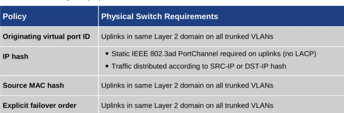
VMware vSphere 4.0 supports a number of teaming policies for VMware vSS port groups and VMware vDS distributed virtual port groups. All these policies will work in 10 Gigabit Ethernet environments (Table 2).
Table 2. Teaming Policy Options
Policy Physical Switch Requirements
Originating virtual port ID Uplinks in same Layer 2 domain on all trunked VLANs
IP hash ●Static IEEE 802.3ad PortChannel required on uplinks (no LACP)
●Traffic distributed according to SRC-IP or DST-IP hash Source MAC hash Uplinks in same Layer 2 domain on all trunked VLANs
Explicit failover order Uplinks in same Layer 2 domain on all trunked VLANs
Of these, the originating virtual port ID is the usual best practice recommendation for even
distribution of virtual ports supporting virtual machines and vmkernel applications over the available physical NICs (vmnics). This methodology is acceptable for a dual-10 Gigabit Ethernet environment.
IP hash is also a viable policy. IP hash requires the uplinks to be aggregated into a static
PortChannel. This approach is similar to the vPC configuration for the Cisco Nexus 1000V; however, since the VMware vSS and vDS do not support LACP, the adjacent switches must be configured for a static PortChannel with LACP disabled (channel-group mode on).
Source MAC hash should be used only if you have multiple MAC addresses assigned to a vnic and you require additional load distribution over the available uplinks. Originating virtual port ID is preferred over this method for increased efficiency.
Explicit failover order uses the highest-order uplink from the list of active adapters that pass failover detection. If one link fails, the next link from the list of standby adapters is activated.
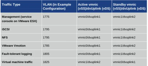
Teaming Policy for Two 10 Gigabit Ethernet Interfaces
In the example in Table 3, the explicit failover order teaming policy is used. In a two 10 Gigabit Ethernet environment, this method provides a deterministic way of directing traffic on a per-port-group or per-distributed-virtual-port-per-port-group basis to a particular 10 Gigabit Ethernet uplink.
The details are as follows:
Virtual switch trunking (VST) mode: Trunk the required VLANs into the VMware ESX or ESXi hosts over both 10 Gigabit Ethernet interfaces and make sure that there is Layer 2 continuity between the two switches on each of those VLANs.
Virtual machine port groups or distributed virtual port groups: Make these active on one vmnic and standby on the other (vmnic1 or vmnic0 in the example).
vmkernel port groups or distributed virtual port groups: Make these active on one vmnic and standby on the other in reverse to that for the virtual machines (vmnic0 or vmnic1 in the example).
Table 3. Example of Teaming Policy for Two 10 Gigabit Ethernet Interfaces
Traffic Type VLAN (in Example
Configuration)
Active vmnic
(vSS)/dvUplink (vDS)
Standby vmnic (vSS)/dvUplink (vDS)
Management (service console on VMware ESX)
1775 vmnic0/dvuplink1 vmnic1/dvuplink2
iSCSI 1795 vmnic0/dvuplink1 vmnic1/dvuplink2
NFS 1795 vmnic0/dvuplink1 vmnic1/dvuplink2
VMware Vmotion 1785 vmnic0/dvuplink1 vmnic1/dvuplink2
Fault-tolerant logging 1805 vmnic0/dvuplink1 vmnic1/dvuplink2
Virtual machine traffic 1825 vmnic1/dvuplink2 vmnic0/dvuplink1
With both NICs active, all virtual machine traffic will use vmnic1, and all the vmkernel ports will use vmnic0. If a switch, link, or NIC failure occurs affecting one uplink, then all traffic will converge to the remaining vmnic. Note that when using VMware vDS, distributed virtual port group teaming policies apply to the distributed virtual uplinks, which then map to the vmnics on each host.
Figure 5 illustrates this mapping and the VLAN assignments for the example configuration. The dotted lines represent the normal traffic flow when all uplinks are available.
Figure 5. Traffic Distribution of vSS and vDS
Other Teaming Policy Variations
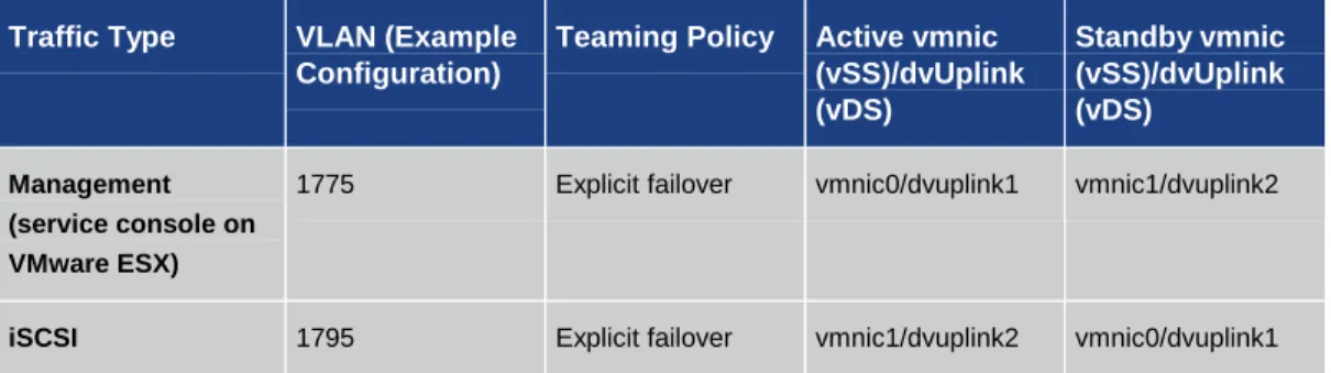
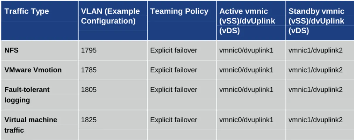
The example in Table 4 illustrates one way to assign deterministic teaming policies to the known traffic types. Every environment is different, so a similar active-standby methodology could be applied that favors another traffic type. For example, if iSCSI traffic needs additional bandwidth and virtual machine traffic is relatively low, then the iSCSI port group or distributed virtual port group policy could specify iSCSI as active on vmnic1 and standby on vmnic0, with virtual machine traffic active on vmnic0 and standby on vmnic1.
Table 4. Alternative Teaming Policy with iSCSI using dedicated 10GigE link
Traffic Type VLAN (Example
Configuration)
Teaming Policy Active vmnic (vSS)/dvUplink (vDS)
Standby vmnic (vSS)/dvUplink (vDS)
Management (service console on VMware ESX)
1775 Explicit failover vmnic0/dvuplink1 vmnic1/dvuplink2
Traffic Type VLAN (Example Configuration)
Teaming Policy Active vmnic (vSS)/dvUplink (vDS)
Standby vmnic (vSS)/dvUplink (vDS)
NFS 1795 Explicit failover vmnic0/dvuplink1 vmnic1/dvuplink2
VMware Vmotion 1785 Explicit failover vmnic0/dvuplink1 vmnic1/dvuplink2
Fault-tolerant logging
1805 Explicit failover vmnic0/dvuplink1 vmnic1/dvuplink2
Virtual machine traffic
1825 Explicit failover vmnic0/dvuplink1 vmnic1/dvuplink2
Another variation involves spreading the virtual machine traffic over both uplinks through the originating virtual port ID policy with both 10 Gigabit Ethernet uplinks active in that port group or distributed virtual port group (Table 5).
Table 5. Teaming Policy with VM traffic distributed over both 10GigE links
Traffic Type VLAN (Example
Configuration)
Teaming Policy Active vmnic (vSS)/dvUplink (vDS) Standby vmnic (vSS)/dvUplink (vDS) Management (service console on VMware ESX)
1775 Explicit failover vmnic0/dvuplink1 vmnic1/dvuplink2
iSCSI 1795 Explicit failover vmnic1/dvuplink2 vmnic0/dvuplink1
NFS 1795 Explicit failover vmnic0/dvuplink1 vmnic1/dvuplink2
VMware Vmotion 1785 Explicit failover vmnic0/dvuplink1 vmnic1/dvuplink2
Fault-tolerant logging
1805 Explicit failover vmnic0/dvuplink1 vmnic1/dvuplink2
Virtual machine traffic
1825 Originating virtual port ID
vmnic0/dvuplink1 vmnic1/dvuplink2
-
When deciding on a teaming policy, understand your environment and traffic requirements and plan accordingly. The teaming policy parameters on the port group and distributed virtual port group configuration panels are powerful mechanisms for controlling the path of traffic through the virtual and physical networks.
Advanced VMware vSS and vDS Options: Using Traffic Shaping to Control and Limit Traffic
If you have concerns about one traffic type dominating and affecting others through oversubscription on one vmnic, then, as an additional option, you can employ the traffic shaper. The traffic shaper controls and limits traffic on a virtual port. Moving the active uplinks for all vmkernel ports to the
management traffic, and fault-tolerant logging are effectively capped, this process really concerns only iSCSI and NFS. You may want to apply the shaper to one or the other of these to limit its effect on VMware VMotion, fault tolerance, and management. Note that in most environments employing 10 Gigabit Ethernet, the use of the traffic shaper is unnecessary.
The traffic shaper is configured on the port group (or distributed virtual port group). On the VMware vSS, the shaper applies only to ingress traffic (relative to the vSwitch from the virtual machine or vmkernel port). In other words, it works in the southbound direction in Figure 5. The VMware vDS supports bidirectional traffic shaping. You need to apply it only on the ingress (southbound) side.
When configuring the traffic shaper, do not specify a value greater than 4 Gbps (2^32) as all parameters have a 4 Gbps modulus applied. For example, an entry of 5 Gbps will result in a 1-Gbps value.
Cisco Nexus 5000 Series Configuration for VMware vDS and vSS
The following code is an excerpt of a Cisco NX-OS Software switch configuration for two Cisco Nexus 5000 Series Switches configured to support VMware vSS and vDS virtual switches. The listing shows the switch-port configuration for the switch interfaces connecting to the VMware ESX or ESXi server.
N5K-1 Configuration
interface Ethernet1/1 switchport mode trunk
switchport trunk native vlan 999
switchport trunk allowed vlan 1775,1785,1795,1805,1825 spanning-tree port type edge trunk
N5K-2 Configuration
interface Ethernet1/1 switchport mode trunk
switchport trunk native vlan 999
switchport trunk allowed vlan 1775,1785,1795,1805,1825 spanning-tree port type edge trunk
The two switches must have VLAN continuity on all trunked VLANs. Note that in Cisco NX-OS, the configuration statement spanning-tree port type edge trunk is used in place of the spanning-tree portfast trunk statement used in Cisco Catalyst Family switch configurations using Cisco IOS Software. Additional parameters can be applied to the configurations in accordance with network best practices and corporate policies.
Conclusion
10 Gigabit Ethernet is an effective way to increase network performance while reducing the inventory and management burden of interfaces, links, and ports.
The Cisco Nexus 1000V and the VMware vNetwork Distributed Switch (vDS) and vNetwork
Standard Switch (vSS) are all 10 Gigabit Ethernet-capable virtual switches. The VMware vDS offers a rich set of virtual networking capabilities with management using the VMware vSphere Client
through the VMware vCenter Server. The Cisco Nexus 1000V offers an exhaustive set of features designed for the utmost level of network control and transparent management and operation between physical and virtual networks.
For More Information
● VMware Virtual Networking Technology website: http://vmware.com/go/networking ● VMware networking blog: http://blogs.vmware.com/networking
● Cisco Nexus 1000V site: http://cisco.com/go/nexus1000v ● Cisco Nexus 1000V deployment guide:
http://www.cisco.com/en/US/partner/docs/switches/datacenter/nexus1000/sw/4_0_4_s_v_1_ 3/high_availability/configuration/guide/n1000v_ha_preface.html
For more information, visit: www.vmware.com
Cisco Systems, Inc. 170 West Tasman Drive San Jose, CA 95134-1706 USA
www.cisco.com Tel: 408 526-4000 800 553-NETS (6387) Fax: 408 527-0883
VMware, Inc 3401 Hillview Ave Palo Alto, CA 94304 USA
www.vmware.com
Tel: 1-877-486-9273 or 650-427-5000 Fax: 650-427-5001
Copyright © 2010. VMware, Inc. All rights reserved. Protected by one or more U.S. Patent Nos. 6,397,242, 6,496,847, 6,704,925, 6,711,672, 6,725,289, 6,735,601, 6,785,886, 6,789,156, 6,795,966, 6,880,022, 6,944,699, 6,961,806, 6,961,941, 7,069,413, 7,082,598, 7,089,377, 7,111,086, 7,111,145, 7,117,481, 7,149, 843, 7,155,558, 7,222,221, 7,260,815, 7,260,820, 7,269,683, 7,275,136, 7,277,998,7,277,999, 7,278,030, 7,281,102, 7,290,253, 7,356,679 and patents pending.
Cisco, the Cisco logo, and Cisco Systems are registered trademarks or trademarks of Cisco Systems, Inc. and/or its affiliates in the United States and certain other countries. All other trademarks mentioned in this document or Website are the property of their respective owners. The use of the word partner does not imply a partnership relationship between Cisco and any other company.