Kantech IP Link
Enhanced Ethernet Device
Tear-out
Quick Setup Sheet
on last page!
Installation Manual
Table of Contents
General Information ...1
Copyright Info ...1
Technical Support ...1
Compliance Specifications ...2
FCC & IC Compliance ...2
UL 294 Compliance Notice ...2
Other UL Compliance ...2
CE & C-Tick Compliance ...2
RoHS ...2
WEEE ...2
Overview ...3
Introduction ... 3
Cover Description ... 4
Configurations Options ... 5
Specifications ... 5
Ordering Information ...6
Models Available ... 6
Installation Manuals ... 6
Site Survey ...6
Network Topology ... 6
Local Area Network (LAN) ... 6
Wide Area Network (WAN) ... 7
LAN Configurations ... 7
Static IP Addressing ... 7
Reserved DHCP IP Addressing ... 7
WAN Configurations ... 8
Static IP Addressing ... 8
Reserved DHCP IP Addressing ... 9
Pre-Installation ...9
Network Configuration ...9
Equipment Checklist ...9
ESD Precautions ...9
Reading Checklist ...10
Site Checklist ...10
Task Lists ...10
Mounting the IP Link ...11
Connecting the Earth Ground ...11
Connecting the IP Link to the Controller Loops ...12
Connecting Power ...13
For KT-300 Controllers only ... 13
For KT-100 and KT-200 Controllers ... 13
Powering Up the IP Link ...14
Defining the EntraPass Site ...14
Verifying Communication with the IP Link ...17
Configuring the IP Link in a WAN/Internet ...17
Preparing the WAN for the IP Link ... 17
Configuring the IP Link at the Remote Site ... 18
Confirming IP Link Communication with the Gateway ... 20
Configuring the IP Link with the Web Configuration Page ...21
Upgrading the IP Link Firmware ...23
General Information
Copyright Info © 2010 Tyco International Ltd. and its Respective Companies. All Rights Reserved. All specifications were current as of publication date and are subject to change without notice. Kantech and the Kantech logo are trademarks of Tyco International Ltd. and its Respective Companies.
Technical Support
For technical assistance with the IP Link and other Kantech products, contact technical support, Monday to Friday. See the following table for all technical support phone numbers.
Country/Region
Phone Numbers
Support
Hours
North America Toll Free +888 222 1560 (GMT -05:00)
US and Canada Direct: +450 444 2030Fax: +450 444 2029 8:00 to 20:00 [email protected]
Latin America (GMT -03:00)
Argentina
Direct: +5411 4717 2929 Direct: +5411 4717 1320 Direct: +5411 4717 5525 Fax: +5411 4717 1060
9:00 to 18:00 [email protected]
Asia (GMT +08:00)
Singapore
Direct: +65 6319 9820 Fax: +65 6319 9821 Direct: +65 6389 8297
Fax: +65 6389 8292
8:30 to 18:00 [email protected][email protected]
Europe Toll Free +800 CALL TYCO / +800 2255 8926 (GMT +01:00)
Bahrain +800 04127
8:00 to 18:00 [email protected]
France +33 04 72 79 14 83
Greece +00 800 31 22 94 53
Russia +8 10 800 2052 1031
Spain +900 10 19 45
Turkey +00 800 31 92 30 37
United Arab Emirates +800 0 31 0 7123
United Kingdom
+44 08701 ADT SUP / 44 08701 238 787 Direct: +31 475 352 722
Compliance Specifications
FCC & ICCompliance
This device complies with Part 15, Class A of the FCC rules. Operation is subject to the following two conditions: (1) this device may not cause harmful interference, and (2) this device must accept any interference received including interference that may cause undesired operation. This class A digital apparatus meets all requirements of the Canadian Interference Causing Equipment Regulations.
UL 294 Compliance Notice
• UL Standard for access control system units.
• The IP Link is UL 294 listed for supplementary use with EntraPass, KT-300 Controllers, ioProx Proximity readers, and T.Rex request to exit devices.
• Each IP Link enclosure will be installed in a secured and protected location.
• Each IP Link will be equipped with an AC powered LED installed outside the IP Link and connected to an inboard relay, and visible at all time to monitor relay status, as per UL 294, section 32.1.5. • The PCB has been evaluated by UL for use with the original enclosure and the optional
KT-IP-CAB enclosure.
Other UL Compliance
In order to comply with UL listings, the following has to be respected: • Use of a UL listed 60950 computer
• Use only UL listed or recognized cables • Use only UL listed or recognized adaptors
CE & C-Tick Compliance
EN55022: Information technology equipment, radio disturbance characteristics. EN55024: Information technology equipment, immunity characteristics.
EN50133-1: Alarm systems - Access control systems for use in security applications: system requirements.
EN61000-6-1: Electromagnetic Compatibility (EMC) - Generic Standards - Immunity for residential, commercial and light-industrial environments.
EN61000-6-2: Electromagnetic Compatibility (EMC) - Generic Standards - Immunity for industrial environments.
RoHS The RoHS Directive stands for "the restriction of the use of certain hazardous substances in electrical and electronic equipment". This Directive bans the placing on the EU market of new electrical and electronic equipment containing more than agreed levels of lead, cadmium, mercury, hexavalent chromium, polybrominated biphenyl (PBB) and polybrominated diphenyl ether (PBDE) flame retardants.
WEEE This Directive is for Waste Electrical and Electronic Equipment and addresses the disposal and the environmental handling of these products.
Overview
Introduction
The Kantech IP Link makes it easy and affordable to operate your Kantech security system over a network. Unlike other similar devices, the IP Link asynchronously polls the controllers (KT-100, KT-200, KT-300) and communicates with the EntraPass Gateway only when necessary. This significantly reduces the amount of bandwidth required to operate your security system on the network.
The IP Link is essential in determining what to do with specific events and commands. The IP Link directs specific events it receives from any controller to the EntraPass Gateway. On the other hand, it sends commands from the EntraPass Gateway to the appropriate controller.
The IP Link is easy to configure. Use the EntraPass workstation, a web browser or an intuitive stand-alone application called the KT-Finder. The KT-Finder is a small application used to locate an IP Link on a local area network (LAN).
The IP Link is extremely secure. It uses 128-bit AES encryption to communicate with the Gateway which prevents any hacking from the Internet and ensures secure communications when used over the Internet on a wide area network (WAN).
• Secure communication via 128-bit AES encryption • Minimal bandwidth usage
• Supports up to 32 controllers per IP Link
• Compatible with EntraPass Special Edition, Corporate Edition and Global Edition with Corporate Gateway
Note: Kantech recommends a VC-485 for each site. If there is a loss of communication with one of the controllers, the VC-485 will preserve communication with the other controllers.
Cover Description
The IP Link has a red status LED called Heartbeat Patterns (with cover) or STAT (without cover). The main purpose is to indicate if EntraPass is present and if the polling occurs. Table 1 describes the various heartbeat patterns that are used. See Table 2 for the description of the other status LEDs.
Table 1: Status LED Heartbeat Patterns
Pulses Description Patterns
Steady ON for 15 secs
IP Link is booting.
1 quick flash/sec. IP Link is configured and communicating with the Gateway.
1 long flash/sec. IP Link is in Factory Default (DHCP) mode
3 flashes in 3 secs and OFF for 1 sec.
IP Link is in Forced Static IP mode (192.168.1.2) and in Factory Default.
2 quick flashes/sec. IP Link is no longer communicating with the Gateway but is configured.
5 quick flashes/sec. IP Link is preparing to reboot.
1 long pulse for 2.5 secs
IP Link has received a broadcast from the Gateway or the KT-Finder. After this delay, the IP Link returns to its previous heartbeat pattern. Useful to verify network communication.
Configurations Options
The IP Link can be configured through 3 different options:
• With EntraPass, when the IP Link is within the same local area network (LAN)
• With the KT-Finder application locally through the LAN or remotely through the Internet or wide area network (WAN).
• With a web browser like Internet Explorer locally only (LAN)
Specifications
Table 3: Environmental and Electrical Specifications
Table 4: IP Link Specifications
Table 5: Characteristics with EntraPass Table 2: Network status LEDs
Speed remains OFF in a 10BaseT network, remains ON in a 100BaseT network.
Activity blinks to show network activity, and
steady when there is intense network activity.
Link turns ON when the network is present, turns OFF when there is no network.
Description Specifications
Operating Temperature 0°C to 49°C (32°F to 122°F)
Humidity Level 0 to 85% non-condensing, indoor use only DC Power Input 12 VDC
Input current 175 mA
Description Specifications
Dimensions 26.7 x 9.5 x 3.12 cm (10.5 x 3.72 x 1.23 in)
Weight 0.6 kg (1.3 lbs)
PCB dimensions 8.30 x 13.30 cm (3.25 x 5.25 in)
Communication Ports RJ-45 Ethernet 10/100Base-T and RS-232 Communication Speed Up to 115200 Baud for serial communication
Flash ROM 2 MB
RAM 8 MB
Description Specifications
Maximum number of controllers per IP Link 32
Maximum number of sites per Gateway in EntraPass Corporate Edition and Global Edition with Corporate Gateway
512 Maximum number of controllers in EntraPass Special Edition 64
Ordering Information
Models Available
• KT-IP: IP Link PCB with metallic cover and wall plate. • KT-IP-PCB: IP Link PCB and parts.
• KT-IP-CAB: Cabinet. Use with KT-IP-PCB only.
Installation Manuals
All IP Link manuals are available as free downloads at www.kantech.com. • DN1670 - English
• DN1671 - French • DN1672 - Spanish • DN1692 - German • DN1693 - Italian
Site Survey
Before starting the installation of the IP Link, you have to determine the configuration that best corresponds to your network architecture. This information is crucial for the proper operation of the Kantech products that you will install. Contact the Network Administrator of the site(s) where you will install the IP Link so that they can provide you with all the network information.
Gather the network information required to configure the IP Link and complete the Network Configuration Information Sheet provided at the end of this document.
We have divided this manual so that as soon as you determine the pertaining type of architecture and environment, you can follow the configuration instructions that correspond to your environment before connecting additional components.
Network Topology
Local Area Network (LAN)
A LAN connects network devices over a relatively short distance. A networked office building, school, or home usually contains a single LAN, though sometimes one building will contain a few small LANs, and occasionally a LAN will span a group of nearby buildings.
Table 6: Bill of Material
Item Description KT-IP KT-IP-PCB KT-IP-CAB
IP Link PCB with cover and wall plate 1 -
-IP Link PCB only - 1
-Flat cable with RJ-12 male connector, 1.8 m / 6 ft. 1 1
-Ground wire pack 1 1 1
Nylon standoffs 5 5
-Light pipes 4 -
-Taping screws 4 -
-Installation manual DN1670 - English 1 1
-Installation manual DN1671 - French 1 1
Wide Area Network (WAN)
As the term implies, a wide area network spans a large physical distance. A WAN like the Internet spans most of the world. A WAN is a geographically-dispersed collection of LANs. A network device called a router connects LANs to a WAN. In IP networking, the router maintains both a LAN address and a WAN address.
In addition, you will notice that there are two constants in LAN and WAN network topologies: • Assigning the IP address for communication between the controllers and EntraPass • Managing both types of IP addresses, static and dynamic
We recommend that you carefully read the following section in order to correctly select the configuration that matches the network architecture where you will install the IP Link.
LAN Configurations
There are two LAN configurations for the IP Link:
Note: Kantech recommends the use of a Static or Reserved DHCP IP address for the IP Link and the Gateway.
Static IP Addressing
You will use this type of configuration in an environment where the Network Administrator will determine the IP address for communication between EntraPass and the IP Link. We recommend using the EntraPass application to configure the IP Link. The other 2 methods, the KT-Finder and the Web Configuration Page, can be used when the PC has no EntraPass application running.
Reserved DHCP IP Addressing
You will use this type of configuration in an environment where the customer DHCP server assigns the IP address automatically to the IP Link. Additionally, the IP address of the IP Link will have to remain the same, which is called Reserved DHCP. We recommend using the EntraPass application to
configure the IP Link. The other 2 methods, the KT-Finder and the Web Configuration Page, can be used when the PC has no EntraPass application running.
WAN Configurations
When sites are distant from each other and protected by the router’s firewall, the public IP address must be used for communication between EntraPass and the remote IP Link. The Network Administrator must provide you the Public IP addresses (local and remote). The public IP address is provided by the local Internet Service Provider (ISP) which controls the IP address.
Note: Kantech recommends the use of a Static or Reserved DHCP IP address for the remote IP Link and the Gateway since the routers must be configured for port forwarding.
There are two WAN configurations for the IP Link:
Static IP Addressing
You will use this type of addressing in an environment where the Network Administrator will determine the IP address for communication between EntraPass and the IP Link. Since the EntraPass application is at the host site, you must use the KT-Finder to configure the IP Link.
Reserved DHCP IP Addressing
You will use this type of addressing in an environment where the customer DHCP server assigns the IP address automatically to the IP Link. Since the EntraPass application is at the host site, you must use the KT-Finder to configure the IP Link.
Pre-Installation
It is important at this stage, if you have not already done so, to contact the Network Administrator where the IP Link will be installed so that you can complete the Network Configuration Information Sheet. We suggest that you always have the Network Configuration Information Sheet close by, and keep a copy with your IP Link.
Confirm that all parts are in order, all necessary tools are available, and that the site is properly prepared.
If you are connecting your IP Link to EntraPass, you must make sure that you are running EntraPass v4.00 or higher.
Network Configuration
• Network Configuration Information Sheet is fully completed
Equipment Checklist
• IP Link
• RS-232 cabling • Installation Manual • VC-485 (recommended) • Network cable
• Network crossover cable for direct connection from PC to IP Link
ESD Precautions
ElectroStatic Discharge (ESD) can damage electrostatic sensitive devices. Use antistatic protection to avoid the risk of equipment damage.
Reading Checklist
We strongly suggest that you keep the corresponding EntraPass reference manual close at hand: • EntraPass Global Edition Reference Manual, DN1316
• EntraPass Corporate Edition Reference Manual, DN1415 • EntraPass Special Edition Reference Manual, DN1420 • KT-300 Installation Manual, DN1315
• KT-200 Installation Manual, DN1659 • KT-100 Installation Manual, DN5073
Site Checklist Ensure the following:
• The mounting site is ready.
• The site has been approved and all wiring complies with UL requirements and other codes as appropriate.
• All preliminary site work is completed and the site is clean and free of dust or other contaminants.
Task Lists
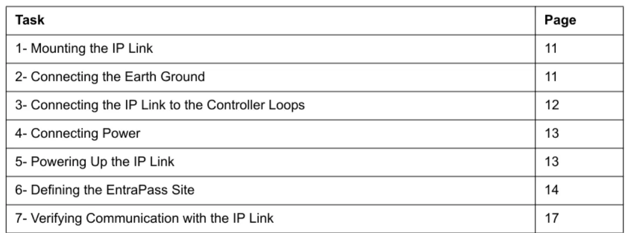
Table 7 lists the tasks for the configuration of the IP Link in a LAN
Table 8 lists the tasks for the configuration of the IP Link in a WAN
Table 7: Task list for a LAN configuration
Task Page
1- Mounting the IP Link 11
2- Connecting the Earth Ground 11
3- Connecting the IP Link to the Controller Loops 12
4- Connecting Power 13
5- Powering Up the IP Link 13
6- Defining the EntraPass Site 14
7- Verifying Communication with the IP Link 17
Table 8: Task list for a WAN configuration
Task Page
1- Mounting the IP Link 11
2- Connecting the Earth Ground 11
3- Connecting the IP Link to the Controller Loops 12
4- Connecting Power 13
5- Powering Up the IP Link 13
6- Defining the EntraPass Site 14
1- Mounting the IP Link
The installation process consists of installing your IP Link and then configuring from EntraPass or the KT-Finder, depending on the network configuration. First mount the IP Link, connect power and grounding connections, then wire the controller loop to the IP Link.
The IP Link does not require any additional enclosures.
• It must be mounted in a secure, yet accessible, location that supports the environmental conditions listed in the environmental specifications. See Table 3 on page 5.
• Leave 23 cm (8 in) clearance space around the sides, and at least 33 cm (13 in) space in front. • Avoid placing the IP Link near electrical or communication devices.
• Install the IP Link on the selected wall using four tapping screws fed through the mounting holes.
Mounting hole positions
2- Connecting the Earth Ground
Connect the provided green ground wire from the EARTH terminal to the cover screw. Use a single conductor solid copper wire to ground the IP Link to a good earth ground as per the local building code.
3- Connecting the IP Link to the Controller Loops
The IP Link can connect to all Kantech controllers such as the KT-100, KT-200 and the KT-300. The KT-100 only uses RS-485, the KT-200 and KT-300 accept both.
• See Table 9 and Figure 1 for RS-232 connection to a VC-485 with RJ12 connector • See Table 9 and Figure 2 for RS-232 connection to a KT-300 with RJ12 connector • See Figure 3 for RS-232 connection to a KT-200
Note: Always use the same controller model within the same site or loop.
Table 9: RS-232 Wiring to IP Link
Figure 1: RS-232 connection with RJ12 to VC-485 (KT-100, KT-200 and KT-300)
Figure 2: RS-232 connection with RJ12 to KT-300 #1 (only with KT-300)
RJ12 connector on TX RX GND
VC-485 GRN RED BLK
Figure 3: RS-232 connection to KT-200 #1
4- Connecting Power
For KT-300 Controllers only
• Use the 12V DC from the 12V AUX terminals.
For KT-100 and KT-200 Controllers
5- Powering Up the IP Link
1. Power up the IP Link.
2. Make sure the IP Link is in Factory Default (DHCP) mode before starting the configuration. See
Table 1 on page 4 for the heartbeat patterns per state. 3. Connect the network cable.
6- Defining the EntraPass Site
Before you start These items must be completed and verified:
• The detachable Network Configuration Information Sheet is fully completed. • You are running EntraPass version 4.03 or higher.
Note: If you are running EntraPass Corporate Edition or EntraPass Global Edition; the following system components should have been installed and configured:
- an EntraPass Workstation, - an EntraPass Corporate Gateway.
The IP Link communicates locally with EntraPass through a10/100 Base-T Ethernet connection. 1. From the Devices menu, go to Site, or click on Devices > Site.
2. Click on New, located in the top left corner of the Site/Loop screen, to create a new site.
3. Enter the site name for both languages.
4. Under the General tab, select Secure IP (IP Link) from the Connection type menu. 5. Enter the Number of controllers.
Note: The maximum number of controllers per IP Link is 32. 6. Complete the other settings as required.
7. Click on the IP Device IP Configuration tab.
8. Look on the IP Link for the MAC address sticker next to the terminal strip and complete the MAC address of the IP Link.
Note: The 1st 6 digits are already displayed and can’t be modified: 00:50:F9:00:00:00. 9. Make sure the Online option is checked.
10.Enter the required information as specified in the Network Configuration Information Sheet. • For a Static IP address, click Use the following IP address and enter the information.
• For a Reserved DHCP IP address, click Obtain an IP address automatically.
Example when obtaining an IP address automatically
11. Enter the IP address or the Domain name of the EntraPass Special Edition / Corporate Gateway. 12.Select a Protocol (UDP or TCP) from the dropdown list.
13.Enter a port number.
• For TCP: No port required.
• For UDP: Enter the Port number used by the IP Link (port 18810 by default). If more than one IP Link resides at the same IP address (WAN/Internet applications) then it will require the use of a unique port number per IP Link. See Procedure 8 on page 17.
14.Click on the IP Device Automated Connection tab.
15.Make sure the Broadcast configuration option is checked for LAN configuration.
Note: Leave the option Enable KT-Finder diagnostic for IP device checked, to be able to view and troubleshoot the IP Device configuration with the KT-Finder.
Note: To configure the system using a public IP address (LAN/WAN), please refer to Configuring the IP Link at the Remote Site on page 18 for more details.
16.Click on the IP Device Parameters tab.
17.Verify the Encryption key. A random key is generated automatically. 18.Select the Controller’s loop baud rate.
Note: The maximum baud rate for the KT-200 controller is 19200.
19.The settings in the Delays section refer to the communication with the Gateway. In order to display the connection status of the IP Link with EntraPass and to avoid large amount of traffic, the IP Link sends a heartbeat to EntraPass at a pre-configured interval (60 seconds for example). If EntraPass is not answering after this amount of time, the IP Link will retry several times and then stop the polling if no answer is received.
• Heartbeat frequency (mm:ss): The time range value is from 0:15 to 10:00. This is the heartbeat frequency from the IP Link to the Gateway.
• Fail to report after (mm:ss): The time range value is from 3:00 to 59:59. This is the time that the Gateway will wait before declaring IP Link communication failed.
• Fail-soft delay on gateway communication failure (mm:ss): The maximum time range value will follow the selection from the Heartbeat Frequency. This is the time that the IP Link will take to verify if there is a communication failure with the Gateway before it operates in stand-alone mode.
• Retry count: The range value is 1 to 15. This is the number of times that the IP Link will retry to confirm communication failure with the Gateway.
• Maximum wait on send command (s:cc): The time range value is from 1:00 to 9:99. This is the maximum time allowed for the IP Link to acknowledge a command sent from the EntraPass workstation.
7- Verifying Communication with the IP Link
1. Verify the communication status between the new IP Link and the Gateway. From the EntraPass workstation Operation menu, select Site.
2. Select the Gateway from the Gateway List.
Note: For the EntraPass Special Edition application, there is no Gateway List selection. The Communication status must read as follows: IP Link communication OK.
If the communication status does not indicate IP Link communication OK, check the descriptions for the other messages:
• Broadcast IP Link succeeded waiting for heartbeat: Broadcast confirmation to IP Link. • IP Link communication unknown: The IP Link is starting up.
• IP Link communication failed: The IP Link has failed to report to the Gateway.
• Failed to reach IP Link: The Gateway is not receiving the IP Link confirmation. - Check if network cable is connected to RJ-45 connector on IP Link.
8- Configuring the IP Link in a WAN/Internet
Preparing the WAN for the
IP Link
When using the IP Link in a WAN configuration behind a router/firewall, it is necessary to forward port(s) for both the local (Gateway) and the remote (IP Link) sites. Typically, this will be performed by the Network Administrator.
UDP:
1. Ports used at the Corporate Gateway location: Forward ports 18001 and 18801 to the IP address of the Gateway.
If the IP Link is within the then go to
local DHCP server (LAN) Step 1.
remote DHCP server (WAN) Procedure 8 on page 17.
Table 10: Gateway Ports
Purpose Port
Firmware upgrade 18001
2. Ports used at the remote site (IP Link): Forward port 18810 to the IP address of the IP Link.
Note 1: If you are using more than one IP Link at the same remote site, it is necessary to use a unique port number for each IP Link. This information is used in Procedure 6, Step • Note 2: This port is used to configure the IP Link with a Web Browser and should not be forwarded.
This will restrict its use to the LAN only.
TCP:
1. Ports used at the Corporate Gateway location:
Configuring the IP Link at the Remote Site
The KT-Finder is an application used to configure the IP Link over the local area network (LAN) or the wide area network (WAN).
Important: The KT-Finder application is on the EntraPass CD-ROM and is also available as a free download from www.kantech.com. It doesn’t require any installation.
1. Quit all EntraPass applications.
2. Make sure there is a DHCP server on site and the IP Link is in Factory Default (DHCP) mode. See
Table 1 on page 4. 3. Start the KT-Finder.
Note: If you try to run the KT-Finder while running EntraPass, you will get an error message similar to this.
4. Select IP Link from the Device menu.
Table 11: IP Link Ports
Purpose Port
Broadcast and KT-Finder 18803
Communication with the Gateway 18810 (Note 1) Web Configuration Page 80 (Note 2)
Table 12: Gateway Ports
Purpose Port
Firmware upgrade 18802
5. Enter the MAC address of the IP Link then click on Connect.
6. When the IP Link is found, the configuration page will display.
7. Verify your Network Configuration Information Sheet:
• Enter the EntraPass IP address or the Domain name of the EntraPass Special Edition / Corporate Gateway. This information must be the same as entered in Procedure 6 Step 11.
8. Select the Protocol (UDP or TCP) 9. Change the Port number, if required.
Note: The port number should only be changed when you have more than one IP Link at the same remote site.
10.Click OK.
11. Repeat the procedure for each IP Link at this site.
Confirming IP Link Communication with the Gateway
The IP Link should begin communicating with the Gateway within a few minutes. To confirm that they are communicating, please verify the following:
12.Verify that the IP Link heartbeat pattern LED is flashing 1 quick flash/sec. as per Table 1 on page 4. 13.Verify communication between the new IP Link and the Gateway. From the EntraPass workstation
Operation menu, select Site and then select the Gateway from the Gateway List.
Note: For the EntraPass Special Edition application, there is no Gateway List selection. The Communication status must read as follows: IP Link communication OK.
If the communication status does not indicate IP Link communication OK, check the descriptions for the other messages:
• IP Link communication unknown: The IP Link is starting up.
• IP Link communication failed: The IP Link has failed to report to the Gateway.
• Failed to reach IP Link: The Gateway is not receiving the IP Link confirmation through the communication port 18801.
- Check if network cable is connected to RJ-45 connector on IP Link.
- Verify configuration port number if there are more than one IP Link at the remote site. - Verify port forwarding assignments at both sites, see Table 10 on page 17 and Table 11 on
page 18.
Configuring the IP Link with the Web Configuration Page
This procedure is practical if you want to configure the IP Link(s) in advance before going on site.
Note: The Web Configuration Page is available only while the IP Link is in Forced Static IP.
Before you start • The detachable Network Configuration Information Sheet is fully completed.
• Determine your connection to the IP Link and choose the appropriate network cable that you need. See below for an example with each type of network cable.
1. Make sure the IP Link is in Forced Static IP before starting the configuration. Verify the heartbeat patterns to determine the status, see Table 1 on page 4 and Table 13 on page 26 to put the IP Link in Forced Static IP.
3. Start your web browser and enter the following IP: 192.168.1.2 and press Enter.
4. Enter the IP addresses as per the Network Configuration Information Sheet but do not click on the
Save configuration to IP Link button yet.
5. Remove the wire between PGM2 and IN2 on the IP Link. 6. Click on the Save configuration to IP Link button.
7. When you will go to the site with the configured IP Link, you will have to enter the same details into the EntraPass workstation.
Upgrading the IP Link Firmware
Warning: You will loose communication with all your controllers for up to 5 minutes during this upgrade. This must be planned accordingly.
1. Verify the communication status between the IP Link and the Gateway. From the EntraPass workstation Operation menu, select Site.
2. Select the Gateway from the Gateway List.
Note: For the EntraPass Special Edition application, there is no Gateway List selection. The Communication status must read as follows: IP Link communication OK.
3. Confirm the firmware version before proceeding. Right click on the site name to view the contextual menu.
4. Select Full status to view the firmware version.
6. From the Options menu, select System Parameters.
7. From the Firmware section, click on the IP Link tab.
8. Make sure the Enable TFTP IP Link updater option is checked. 9. Click on the 3 dots to locate the firmware file.
10.Select the firmware file and click OK.
11. Click OK to close the System Parameters dialog. 12.From the Operation menu, select Site.
13.Select the Gateway from the Gateway List.
Note: For the EntraPass Special Edition application, there is no Gateway List selection. 14.Click on the site that corresponds to the IP Link to highlight it.
15.Click on the reload firmware button.
16.A confirmation will display.
17.Click Yes.
18.The IP Link will reset and restart with the new firmware.
Warning: That process could take up to 5 minutes.
The communication status in the Operation > Site will say IP Link Communication Failed then back to IP Link Communication OK.
19.Right click on the site name to view the contextual menu.
20.Select Full status to view the new firmware version.
21.Two very important status messages must be listed as well:
• IP Link communication OK for IP Link communication status with the Gateway.
• Site communication OK for controllers communication, through the IP Link, with the Gateway. 22.Click Close.
How to Reset the IP Link
For maintenance or configuration purposes, the IP Link can be reset. Two types of resets can be performed: Factory Default (DHCP) and Forced Static IP.
Table 13: Reset options
Figure 4: Terminal positions for resets
Resets Instructions
Factory Default (DHCP)
WARNING: This reset will clear all IP Link configuration including the IP address.
1. Disconnect DC power.
2. Connect a wire between the PGM1 and IN1 pins.
There should be no wire between PGM2 and IN2.
3. Connect power.
4. Wait 60 secs. The Heartbeat Patterns or STAT LED should be steady red, then blink very quickly.
5. Remove the wire between PGM1 and IN1. 6. See Table 1 on page 4 for the heartbeat patterns:
1 long flash per sec.
7. The IP Link will now be in DHCP mode and will attempt to obtain an IP address automatically from the DHCP server.
Forced Static IP
(192.168.1.2) and Factory Default
WARNING: This reset will clear all IP Link configuration and temporarily assign 192.168.1.2 as an IP address so that the IP Link may be configured using a Web Browser or the KT-Finder.
1. Disconnect DC power.
2. Connect a wire between the PGM1 and IN1 pins. 3. Connect a wire between the PGM2 and IN2 pins. 4. Connect DC power.
5. Wait 60 secs. The Heartbeat Patterns or STAT LED should be steady red, then blink very quickly.
6. Remove only the wire between PGM1 and IN1. 7. See Table 1 on page 4 for the heartbeat patterns:
3 flashes in 3 secs and OFF for 1 sec.
8. The IP Link will now be accessible at IP address 192.168.1.2. Configure the IP Link using either the KT-Finder or the Web Configuration Page.
9. Save the configuration and wait at least 1 min. to let the IP Link restart.
DN167 7 . The p arameters yo
u will de
fine in this secti
on dep
end
s
on
the
type of inst
alla
tion you
have: •
If the
IP Link is inst
all
ed on the same subn
et (LAN) as th
e PC d efi ned in S select Local IP addres s • If the
IP Link is inst
all
ed on a dif
fere nt sub net (W AN), e nter the IP Link Public address (or Domain name ). T ypica lly
, this is th
e ro uter a ddre ss/na me . 8 .
Click on the fl
opp
y ico
n
to save you
r con fig uration . 9 . Close wi ndow . 10 .G o to O per ati
on > Si
te
, select the
Gateway . 1 1 .V e rif
y the IP Li
nk Co mmu nica tio n st atu s . .0 a nd hig her , go to Dev ices > Site. Sele
ct an exi
stin g Gat eway an d o r c rea te a ne w si te . Numbe r o f controllers . se
Enhanced Ethernet (IP Lin
k) a s con nection type. Mo ve to the IP Configuratio n tab. MAC address . se Ob ta in th
e IP ad
dr ess au tom atic ally or Use th e follo w in
g IP ad
dr ess . IP ad dress (o r Domain name ) of th e PC on w hich Entra P ass S p ec ia l o n /Corpo rat e Gateway is inst all ed. Mo ve to the IP Li nk Au toma te d c tion tab.
Network Configuration Information Sheet
Please complete one sheet per IP LinkCompany Name:
Site Name:
LAN
or
WAN (see other side)
IP Link Configuration in a Local Area Network (LAN)
For more details, see Procedure 6: Defining the EntraPass Site on Page 14.
MAC Address: 00:50:F9: ______:______:______
Protocol: _________
Port (UDP only) _________
IP Address Type:
DHCP
or
Static
IP Address: ______.______.______.______
Subnet Mask: ______.______.______.______
Default Gateway (Router): ______.______.______.______
Network Configuration Information Sheet
IP Link Configuration in a Wide Area Network (WAN)
EntraPass Site
For more details, see Procedure 6: Defining the EntraPass Site on Page 14.
EntraPass Special Edition / Corporate Gateway
IP Address: ______.______.______.______
Router
Public IP Address:______.______.______.______
orDomain name: ____________________________
Port Forwarding Checklist
For more details, see Procedure 8: Configuring the IP Link in a WAN/Internet on Page 17.