Electronic Communications of the EASST
Volume 21 (2009)
Guest Editors: T. Levendovszky, L. Lengyel, G. Karsai, C. Hardebolle Managing Editors: Tiziana Margaria, Julia Padberg, Gabriele Taentzer
Proceedings of the
3
rdInternational Workshop on
Multi-Paradigm Modeling
(MPM 2009)
Modeling and Formal Verification of a Passive Optical Network on
Chip Behavior
Luiza Gheorghe Iugan, Gabriela Nicolescu and Ian O’Connor
ECEASST
Modeling and Formal Verification of a Passive Optical Network on
Chip Behavior
Luiza Gheorghe Iugan1, Gabriela Nicolescu1 and Ian O’Connor2
1
(luiza.gheorghe, gabriela.nicolescu)@polymtl.ca Department of Computer Science Ecole Polytechnique de Montréal
2
[email protected] Department of Electronic, Electrical and Control Engineering Ecole Centrale de Lyon
Abstract: Many of the modern Systems-on-Chip integrate a high density of heterogeneous components such as different processors, a wide range of hardware components, as well as complex interconnects that use different communication protocols. On-chip physical interconnections represent a limiting factor for the performance and energy consumption. Currently, the optical interconnects integrated on chip are a viable alternative for on chip interconnects. However, the access to physical prototyping of these interconnects is a major challenge because this systems require very recent technologies, still difficult to access. Thus, their high-level modeling and validation are mandatory. This paper proposes the modeling and the formal verification for the global validation of the behavior of a passive integrated photonic routing structure using models that are based on timed automata.
Keywords: Timed Automata, Formal Verification, Optical Network on Chip, Abstraction Levels.
1
Introduction
Modeling and Formal Verification of ONoCs
verification approach [ITRS]. This implies that the design model is more thoroughly checked and more cases are taken into consideration.
This paper proposes the modeling and the formal verification for the global validation of the behavior of a passive optical network on chip. The model was realized using timed-automata and was validated through simulation using an integrated tool environment for modeling, simulation and verification of timed automata developed jointly by Uppsala University in Sweden and Aalborg University in Denmark (UPPAAL).
One of the most important characteristics of the ONoC is the non contention. This particularity requires complex models: the number of timed-automata increases and by consequence the verification becomes time consuming. To cope with this complexity, the modeling and the formal verification were realized in two steps. The first step consists of the modeling of the behavior of the network at high level of abstraction. For the second step the abstraction level was lowered, the network was partitioned and therefore the formal verification was realized on segments of the network. By doing so, the deadline verification time was reduced from more then 12 hours to 41 sec.
The paper is organized as follows: section 2 presents the related work. Section 3 introduces the basic concepts of optical interfaces and photonic devices as well as model and formal notions such as timed automata. Section 4 details the model of the behaviour of a 4X4 λ-router as it was introduced in Section 3 while Section 5 explains the formal verification of the behaviour of the passive optical network and presents the properties that were defined and checked. The last section of this paper, Section 6, gives our conclusion.
Here comes the introduction.
2
Related Work
Given the diversity of concepts relevant to the ONoC, the previous work on these networks can be divided in two main groups: one regarding generally, the validation of heterogeneous systems and the other related to the networks on chip, specifically to the ONoCs.
ECEASST
based on a methodology of system level architecture design. The on-chip interconnects are the subject of several academic and industrial analyses. In [Col+03] simple optical and electrical point to point interconnects using a Spice-like simulator are compared. [Tos+04] presents more complex interconnects by comparing optical and electrical clock distribution, using accurate physical simulations, synthesis techniques and predictive transistor models (130 nm to 45 nm). Intel has also studied performance improvements including technological costs between copper and optical clock distribution [Kob+04]. In [SBC07] the authors propose a network on chip combining a photonic circuit-switched network and an electronic network. The architecture is validated using an event driven simulator.
In summary, the previous works concentrated on modeling, simulation or analysis of ONoCs. The contribution of this paper is the global formalization and formal verification of an ONoC.
3
Basic Concepts
This section presents the basic concepts that were used in this work. Firstly, we present the studied optical network on chip and then we introduce the timed automata model used for the formalization of the ONoC. Finally, we give a global view of the UPPAAL tool that we used for the simulation and formal verification.
3.1 Optical Network on Chip
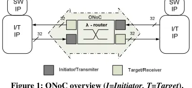
The integrated optical communication system studied in this work, proposed originally in [Con04]0, is composed of three types of blocks: i) transmitters, ii) a passive integrated photonic routing structure (λ-router) and iii) receivers. Figure 1 presents an overview of this ONoC. The transmitters and the receivers are in charge of the optical-electrical conversion.
Figure 1: ONoC overview (I=Initiator, T=Target).
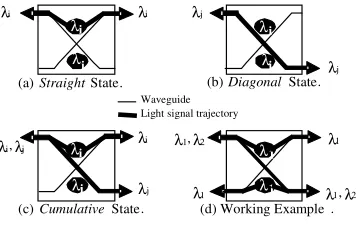
The λ-router is a passive optical network (see Figure 2 (a)(b)) composed of 4-port optical switches based on add-drop filters designed to route data through SoC components .
λ 1
λ1
λ1 λ2
λ2
λ2 λi
λi
λi λN
λN
λN
I1
I2
I3
IN-1
IN
T1
T2
T3
TN-1
TN
Si
Micro-resonator
4-port optical switch example
waveguide
λ-router
(a) (b)
Figure 2: N X Nλλλλ-router architecture (a), 4-port optical switch architecture example (b).
Modeling and Formal Verification of ONoCs
add-drop is bidirectional and compact devices have been demonstrated in CMOS compatible Silicon on Insulator (SOI) technology (Si/SiO2 structures accept 1.3-1.55 µm wavelength)
[Kaz+05].
As illustrated in Figure 3, there are three possible switch states depending on the input signal:
- Straight state 3(a) occurs when specific wavelengths, called resonant wavelengths (λi,
depending on micro-resonator geometry and material) are injected in the filter and are routed through the micro-resonator.
- Diagonal state 3(b) occurs when other wavelengths (λj) are injected in the filter and are not
routed through the micro-resonator.
- Cumulative state 3(c) occurs when signals of both resonant and non-resonant wavelengths (λi and λj) are injected into the filter using the WDM technique1 and are either routed or not
routed through the micro-resonator. Because of this property and the fact that the four add-drop ports can be used simultaneously, a contention-free network can be built.
Waveguide Light signal trajectory
λi
λi λ
j λj λi λi λ1 λ1 λ1
λ1,λ2
(a) Straight State. (b) DiagonalState.
λ i λ1 λi i λi
λi λj
λi,λj
λ1,λ2
(c) Cumulative State. (d) Working Example .
λ
Figure 3: Functional States of a 4-port Optical Switch
The example in Figure 3(d) shows a possible exploitation of the optical switch. This example shows both unidirectional and bidirectional behaviors (several wavelengths simultaneously injected in opposite way).
The main advantage of this architecture is its high scalability. Currently, up to 32 cores (16 initiators and 16 targets) can be plugged onto an ONoC, where the limit is due to the lithographical tolerance in add-drop manufacturing.
In a λ-router, only one physical path associated with one wavelength exists between an initiator Ii and a target Tj. The broadcast is also possible with this architecture.
λ1 1 λ I I I I 2 λ λ3 λ3 4 λ T T T T 1 2 4 3 1 2 3 4
I/T T1 T2 T3 T4
I1 λλλλ2222 λλλλ3333 λλλλ1111 λλλλ4444
I2 λλλλ3333 λλλλ4444 λλλλ2222 λλλλ1111
I3 λλλλ1111 λλλλ2222 λλλλ4444 λλλλ3333
I4 λλλλ4444 λλλλ1111 λλλλ3333 λλλλ2222
I/T T1 T2 T3 T4
I1 λλλλ2222 λλλλ3333 λλλλ1111 λλλλ4444
I2 λλλλ3333 λλλλ4444 λλλλ2222 λλλλ1111
I3 λλλλ1111 λλλλ2222 λλλλ4444 λλλλ3333
I4 λλλλ4444 λλλλ1111 λλλλ3333 λλλλ2222
(a) Truth table. (b) Architecture
Figure 4: 4 X 4λλλλ-router
1 Wavelength Division Multiplexing. Several signals at different wavelengths can be injected into the same
ECEASST
The truth table in Figure 4 (a) represents the operation for a 4 × 4 network (Figure 4 (b)). For example, if I1 communicates with T2, data must use the wavelength λ3 to be sent through the
λ-router (bold line in Figure 4 (b)). At the same time I4 can communicate with T1 using the wavelength λ4 (dash line in Figure 4(b)). These optical switches and λ-router have been
manufactured and tested. The observed network routing corresponds to theory [Kob+04].
3.2 Timed Automata
In our approach timed automata were used for the modeling of the optical network on chip, as a succession of locations and synchronizations between them.
A timed automaton is classical finite state automata with clock variables and logical formulas on the clock (temporal constraints) [AD90]. The constraints on the clock variables are used to restrict the behavior of the automaton. The logical clocks in the system are initialized to zero when the system is started and then increase at the uniform rate counting time with respect to a fixed global time frame [AD90]. The clock constraints are the guards on the transitions. A transition can be taken when the clocks’ values satisfy the guard labeled on it. A guard is a Boolean combination of integer bounds on clocks and clock-differences. With this transition, the variables are updated by r (reset) which is an action performed on clocks. The actions are used for synchronization and are expressed by a (action ) [AD90]. A synchronization label is of the form Expression? or Expression! where ! represents the operator send and ? represents the operator receive.
The semantics for a time automaton is defined as “a transition system where a state or configuration consists of the current location and the current values of clocks” [AD90]. Thus, the state is represented by the tuple: (location, x) where x is the clock. Given the system, we can have two types of transitions between locations: a delay transition when the automaton may delay for some time or an action transition when the transition follows an enabled transition.
Timed automata have the following characteristics that make them desirable for our formal model:
- the ease and the flexibility of systems’ modeling,
- the existence of a whole range of powerful tools that are already implemented and that allow different verification techniques. The tools we used for the verification are state machine based; therefore, a model that facilitates the verification was preferred.
- the adequate expressivity in order to model time constrained concurrent systems.
Our formal model needs to support concurrency thus it was represented as a parallel composition of several timed automata with no constraints regarding the time spent in the locations.
3.3 UPPAAL
Modeling and Formal Verification of ONoCs
The expressions cover clocks and integer variables and are used with the labels: guards, synchronization, assignments or invariant. The models synchronize with each other via channels. In UPPAAL the assignments are evaluated sequentially (not concurrently). On synchronizing transitions, the assignments on the !-side (the emitting side) are evaluated before the ?-side (the receiving side).
The model checker engine in UPPAAL is based on the theory of timed automata and its query language is a subset of computational tree logic, the timed computational tree logic (TCTL). The query language [Beh+05] consists in path formulae and state formulae. The states formulae describe individual states while the path quantifies over traces of the model. The main advantage of UPPAAL is that the product automaton is computed on-the-fly during verification. This reduces the computation time and the required memory space. It also allows interleaving of actions as well as hand-shake synchronization.
In our approach UPPAAL was used for the formal representation and the verification of the integrated passive routing structure.
4
OPTICAL NETWORK ON CHIP MODELING
Contention occurs in a network when two nodes attempt to access a communication channel at the same time. The contention-free property of the optical network on chip increases the complexity of the modeling process. Thus, modeling the transmission of different wavelength in the same time requires a larger number of automata. This makes ONoC models very complex, comparing to other models representing an electrical network for instance that does not provide parallelism.
The routing in the optical network presented here is realized by a 4 X 4 λ-router (as presented in Figure 4). In order to model and validate its behavior we used the timed automata and UPPAAL tool [Beh+05].
Due to the parallelism that is expected in an optical network, the system is represented with 44 processes (and consequently 44 automata), divided in subsystems as follows: four to represent the initiators, 16 for the targets (for each target in Figure 4 (b) we needed four processes, one for each wavelength) and 24 for the routing structure. One of the most useful properties to check in a system is reachability meaning that one wants to check if all the states of an automaton are reachable, meaning for our model that we need to check that there exists an execution starting at the initial state that is the set of initiators {I1, I2, I3, I4} and reaching all the targets {T1, T2, T3, T4} for all the wavelength {λ1, λ2, λ3, λ4}. Our experiments showed that the verification of the reachability for this implementation becomes costly in terms of time and can take more than 12 hours because of the state explosion. Therefore, in order to improve the performances of the optical network model, its modeling and formal verification were realized in two steps:
The first step consists of the modeling and the verification of the global network and for this representation we raised the level of abstraction.
ECEASST
The complete checking takes only 2 seconds for the first step and 41 seconds per initiator for the second step. As one can see the verification time is drastically reduced using the proposed approach. Next section details these two steps.
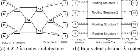
4.1 Global model for 4 X 4λλλλ-router
Figure 5(a) shows the global network at its initial level of abstraction (as a set of four switches and Figure 5(b) shows the equivalent λ-router at a higher level of abstraction. The abstract router (see Figure 5(b)) is modeled as a set of four processes also named here Routing Structures. The four processes model the parallelism provided by the optical network: all the initiators can send data concurrently and all this data will be routed in parallel to the targets by the λ-router. Due to this parallelism, the same target can receive data from the four initiators in the same time. To respect this behavior the abstract router has four inputs (one from each initiator) and 16 outputs (four for each target). Each routing structure connects one initiator with the wavelength corresponding targets. Furthermore, the model has to verify the truth table shown in Figure 4 (a), therefore each target has to have four inputs, one for each wavelength.
(a) 4 X 4 λ-router architecture (b) Equivalent abstractλ-router
Figure 5: Bloc schema of the passive optical 4 X 4λλλλ-router
As a result, the global model of the 4 X 4 λ-router is represented using 24 processes: four processes are used for the initiators, 16 for the targets (as they were previously explained) and four processes for the routing structure, one for each initiator.
Figure 6 shows the timed-automata model, in UPPAAL, for one of the four parallel routing structures that connects an initiator to the targets. The model has only one initial location (a double circle in Figure 6) Start.
Start
ReceiveDataFromInitiator1
lambda:int[lambda1,lambda4] DataToSwitch1?
U U U U
TransmissionToTarget
ToTarget3 ToTarget1 ToTarget2 ToTarget4 DataToTarget3_1!
open3=lambda== lambda1
DataToTarget1_2! open1=lambda ==
lambda2
DataToTarget2_3! open2=lambda ==
lambda3
DataToTarget4_4! open4=lambda ==
lambda4
Figure 6: Routing structure representation
The router will change location from Start to ReceiveDataFromInitiator(n) (where n is the number of the initiator from 1 to 4) following the transition
ator aFromIniti ReceiveDat lambda4]
1, int[lambda : lambda
ch? DataToSwit
Modeling and Formal Verification of ONoCs
it is triggered by the receiving of the data (that is also synchronization between the initiator and the router) from the initiator (DataToSwitch?). The transition also allows the random selection of a wavelength between the four wavelengths of the network λ1, λ2, λ3 and λ4, using lambda:int[lambda1,lambda4]. The location changes then to one of locations ToTarget1, ToTarget2, ToTarget3, ToTarget4, depending of the lambda selection. Each of this transition to a different target is determine by the value of lambda and for each transition there is synchronization DataToTarget! between the router and the corresponding target. The data is received by the corresponding target and the simulation context changes to the processes named here Target that are identified by different indexes. Each one of these processes receives data from the router (DataToTarget?).
4.2 Model for a signal path generated by one initiator
Figure 7 shows the model of the path of the signal generated by one initiator (in this example the initiator I1) at its original level of abstraction. The signal is routed through the four λ
-routers in order to reach the designated targets. The dashed lines and λ-routers represent the paths that are not reached by the signal sent by the initiator I1. Moreover, the model verifies the truth table presented in Figure 4 (a). In the first step I1 can send to the λ-router λ1 four signals corresponding to four different wavelengths. Here the signal corresponding to the wavelength λ1 is sent to λ3 and the remaining three signals are sent to the λ-routerλ2 where a new selection is made.
Figure 7: Signal path in the 4 X 4λλλλ-router for one initiator
As shown in Figure 7, in order to represent the exact path of the signal from the initiator to the targets, the model requires 12 processes: one for the initiator, 4 for the targets (each one with its own wavelength) and seven processes for the routing.
The UPPAAL representation for this model is similar with the one where all initiators were represented. The simulation of the second step of the passive ONoC showed the parallelism between the different signals of different wavelength in the same switch.
5
OPTICAL NETWORK ON CHIP FORMAL VERIFICATION
Using UPPAAl, the models were simulated and they were formally verified. The formal verification consists of checking properties of the system for a broad class of inputs [Beh+05]. For this ONoC we checked properties that fall into three classes:
- Safety properties - the system does not get into an undesirable configuration, (i.e. deadlock) [Mon03]
- Liveness properties - some desired configuration will be visited eventually or infinitely (i.e. expected response to an input) [Mon03]
ECEASST
5.1 Formal verification
The following properties were verified for both the global model and one initiator model.
P0 Absence of deadlock (safety property)
Deadlock exists among a set of processes if every process is waiting for an event that can be caused only by another process in the set. In UPPAAL deadlock is expressed by a formula using the keyword deadlock. A state is a deadlock state if there are no outgoing action transitions either from the state itself or any of its delay successors [Mon03].
A[] not deadlock
P1 Absence of contention (reachability property)
Definition: simultaneous wavelength can be sent through the network and/or through the router, from the same initiator, in the same time. We verified the parallelism for both cases. For the global model the property is:
E<> Switch1.TransmissionToTarget and Switch3.TransmissionToTarget and Switch3.TransmissionToTarget and Switch4.TransmissionToTarget
For the model where the signal generated by one initiator is routed through the network, for one initiator the parallelism in the same switch is encountered in the switches with λ – 3 and 4: E<> Switch3a_1.DataToTarget1 and Switch3a_2.DataToSwitch4 and
Switch3b.DataOutSwitch3b
E<> Switch4_1.DataToTarget3 and Switch4_2.DataToTarget2
P2 Verification of the truth table (safety property)
Definition: there is one and only one wavelength that connects one initiator with one target (truth table in Figure 4 (a)).
For the global network the property is:
A[] Switch1.TransmissionToTarget and lambda==lambda1 imply Target3_1.StartTarget3
A[] Switch1.TransmissionToTarget and lambda==lambda2 imply Target1_2.StartTarget1
A[] Switch1.TransmissionToTarget and lambda==lambda3 imply Target2_3.StartTarget2
A[] Switch1.TransmissionToTarget and lambda==lambda3 imply Target4_4.StartTarget4
For the connection between one initiator and all four targets the property is:
A[] Switch1.TransmissionToTarget and lambda==lambda1 imply Target3.StartTarget3
A[] Switch1.TransmissionToTarget and lambda==lambda2 imply Target1.StartTarget1
A[] Switch1.TransmissionToTarget and lambda==lambda3 imply Target2.StartTarget2
A[] Switch1.TransmissionToTarget and lambda==lambda4 imply Target4.StartTarget4
P3 All locations in the automaton representing the switch are eventually taken (liveness property)
Definition: whenever a wavelength takes the ReceiveDataFromInitiator1 location in the Switch1, it will eventually take the TransmissionToTarget location in the same switch. This property was verified only for the global model.
Modeling and Formal Verification of ONoCs
6
CONCLUSIONS
This paper proposes the modeling, the simulation and the formal verification for the global validation of the behavior of a passive integrated photonic routing structure using models that are based on timed automata. The modeling as well as the simulation and the formal verification were divided in two steps. The first step consisted of the verification of the global 4 X 4 λ –router at a high level of abstraction, as one router behavior while the second step was the representation at a lower level of abstraction of one initiator and the signal path through the optical network. Formal properties were defined and checked for both models.
7
REFERENCES
[BM02] Benini, L.; Di Micheli, G.: Networks on chips: a new SoC paradigm, Computer, vol. 35, 70-77, 2002.
[Con04] O’Connor, Ian et al. Optical solutions for system-level interconnect, SLIP’04, Paris France, 2004.
[ITRS] ITRS. [Online]. Available: http://www.itrs.net.
[LS96] Lee, E.A. and Sangiovanni-Vincentelli, A.L.: Comparing Models of Computation, in Proc. of the IEEE Intl Conference on Computer-Aided Design, 1996.
[Jan03] Jantsch, A.: Modeling Embedded Systems and SoCs - Concurrency and Time in Models of Computation, Morgan Kaufmann Publishers, 2003.
[ZPK00] Zeigler, B.P. ; Praehofer, H. and Kim, T.G. : Modeling and Simulation - Integrating Discrete Event and continuous complex dynamic systems. Academic Press, 2000.
[Bri+07] Brière, M. et al.: “Towards the high level design of optical networks on chip. Formalization of opto- electrical interfaces”, in Proc. of the IEEE ICECS, Morocco, 2007
[Bri+04] Brière, M. et al.: “Design and behavioral modeling tools for optical network-on-chip”, Proc. of DATE’04.
[Bri+05] Brière, M. et al.: Heterogeneous Modeling of an Optical Network-on-Chip with SystemC in Proc.of the Rapid System Prototyping (RSP), 2005.
[Vac+03] Vachoux, A. et al; Analog and mixed signal modeling with SystemC, in Proc. of the IEEE International Symposium on Circuits and Systems (ISCAS), 2003.
[LM+00] Levitan, S.; Martinez, J. et al: Multi technology system-level simulation, in Proc. of the Design Test Integration and Packaging of MEMS/MOEMS (DTIP), 2000.
[Col+03] Collet, J. H. et al., Performance Constraints for On chip Optical Interconnects, IEEE J. Sel. Topics Quantum Electron.,vol. 9, no. 2, 425-432, 2003.
[Tos+04] Tosik, G, et al.: Power dissipation in optical and metallic clock distribution networks in new VLSI technologies, IEEE Electronics Letters, vol. 40, no. 3, 198-200, 2004.
[Kob+04] Kobrinsky, M. et al.: On-chip optical interconnects Intel Technology Journal, vol. 8, 129-142, 2004.
[SBC07] Shacham, A.; Bergman, K. and Carloni, L. P.: On the Design of a Photonic Network-on-Chip, First Inte’l Symposium on Networks-on-Chip, Princeton, New Jersey, 2007.
[Kaz+05] Kazmierczak, A. et al., Design, Simulation and Characterization of a Passive Optical Add-Drop Filter in Silicon-On-Insulator Technology, IEEE Photonic Tech. Lett., vol. 17, 1447 – 1449, 2005.
[AD90] Alur, R., Dill, D.,: Automata for modeling real-time systems, in Proc. 17-th Int. Colloquium on Automata, Languages and Programming, vol. 443, 322-335, 1990.
[Beh+05] Behrmann, G. et al: A Tutorial on UPPAAL, Real-Time Systems Symposium, Miami, 2005.