Mathematical and Software Engineering, Vol. 3, No. 2 (2017), 217-225. Varεpsilon Ltd, varepsilon.com
Parametric Analysis of Isolated Doubled Edged
Hill Diffraction Loss Based on Rounded Edge
Diffraction Loss Method and Different Radius of
Curvature Methods
Mfonobong Charles Uko
1, Uduak Etim Udoka
1, and
Chibuzo Promise Nkwocha
2**Corresponding Author: [email protected]
1
Department of Electrical/Electronic and Computer Engineering, University of Uyo, Uyo, Nigeria
2
Department of Chemical Engineering Federal University of Technology, Owerri (FUTO), Owerri, Nigeria
Abstract
In this paper, parametric analysis of isolated doubled edged hill diffraction loss based on rounded edge diffraction loss method is presented. Particularly, the variation of the diffraction loss due to changes in frequency and radius of curvature of the rounded edge of isolated doubled edged hill obstruction are studied. Also, the ITU-R P.526-13 rounded edge diffraction method is used to compute the diffraction loss. However, the radius of curvature is computed using two approaches, namely, the ITU-R P.526-13 method and the occultation distance based method. The results show that the rounded edge diffraction computed based on the ITU-R P.526-13 radius of curvature method is much higher than the one computed with the occultation distance based radius of curvature approach. At frequency of 1 GHz, the percentage difference in diffraction loss is about 29 % and the difference increases with frequency to as high as 74.5 % at 36 GHz. Similarly, the ITU-R P.526-13 radius of curvature is extremely higher than the occultation distance based radius of curvature. At frequency of 1 GHz, the percentage difference in radius of curvature is about 218 % and the difference increases with frequency to as high as 395 % at 36 GHz. In view of the results, the ITU-R P.526-13 radius of curvature method should be reviewed to ascertain the specific conditions it can be employed.
Keywords: Radius of Curvature; Rounded Edge Obstruction; ITU 526-13 Method;
Occultation Distance; Double Edged Hilltop; Single Edged Hilltop; Fresnel Zone; Radius of Fresnel Zone.
1. Introduction
loss some cases. Consequently, the rounded edge diffraction model was introduced by expert to account for extra diffraction loss that real obstructions present beyond the values obtained through the knife edge model [20-21].
In order to determine the diffraction loss due to rounded edge, the radius of curvature or the rounded edge is first determined. Accordingly, the International Telecommunication Union (ITU) has developed the ITU-R P.526-13 method for computing the radius of curvature for rounded edge diffraction loss computation [22]. In the ITU-R P.526-13 method the radius of the first Fresnel zone is used to determine the portion of the obstruction profile that will be used in the determination of the radius of curvature [22-25]. Consequently, for a given obstruction, with the ITU-R P.526-13 method the radius of curvature varies with frequency since the radius of the Fresnel zone is a function of frequency. However, with another method that is based on the occultation distance [26-27], the radius of curvature does not vary with frequency. Generally, the radius of curvature affects the value of rounded edge diffraction loss. In this paper, the effect of radius of curvature on diffraction loss over isolated doubled edged hill is studied. The ITU-R P.526-13 method gives large values of radius of curvature as the occupation distance of the obstruction increases. Double edged hill tend to have larger occultation distance. As such, this paper seeks to examine the impact of the radius of curvature on the diffraction loss over isolated doubled edged hill with relatively large occultation distance. Sample elevation profile of double edge hill is used in this paper and the analysis is performed for different frequencies in the various microwave frequency band. The diffraction loss results are compared for the two methods of computing the radius of curvature, namely, one based on the ITU-R P.526-13 method and the other on the occultation distance.
2. Theoretical Background
2.1 The Path Profile and Double Edged Hill Obstruction Geometry
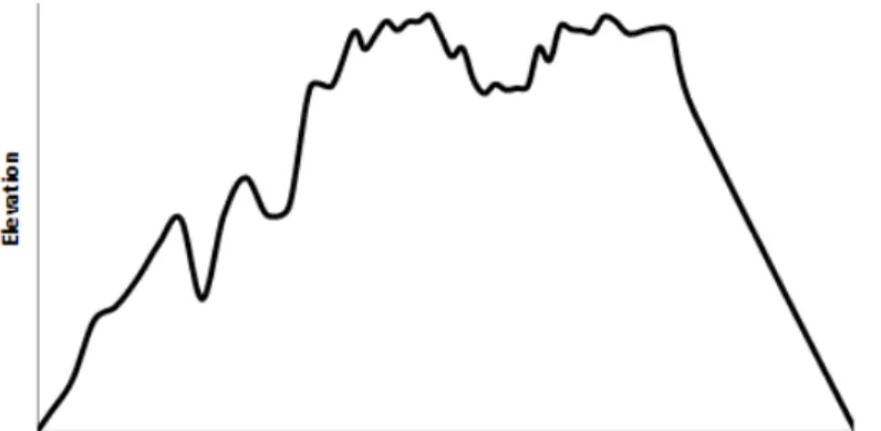
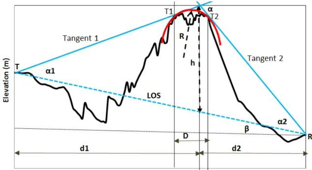
Path profile for a line of sight (LOS) link with double edged hill obstruction is shown in Figure 1 In Figure 2 , a rounded edge of radius, R is fitted in the vicinity of the double edged hilltop. Tangent line referred to as Tangent 1 is drawn from the transmitter to the path profile at point T1 . Another tangent line referred to as Tangent 2 is drawn from the receiver to the path profile at point T2 and extended to intersect the Tangent T1 above the hill vertex. The LOS clearance , h is the height from the LOS to the point of intersection of Tangent 1 and tangent 2, as shown in figure 2 . The occultation distance , D of the obstruction is the distance between T1 and T2. The angle Tangent 1 makes with the LOS is denoted as α while the angle Tangent 2 makes with the LOS is denoted as α . The angle the LOS makes with the horizontal is denoted β.
Figure 2: The Path Profile and Double Edged Hill Obstruction Geometry As shown in figure 2 , is distance from the transmitter to the point where the LOS clearance is measured and is distance from the receiver to the point where the LOS clearance is measured. Let d be the distance between the transmitter and the receiver, then:
d = d + d (1) From figure 2 , β which is the angle the LOS makes with the horizontal is given as:
β = (2)
where
H is the height of the transmitter and H is the height of the receiver and d is the distance between the transmitter and the receiver. The values of d, H and H are obtained from the path profile data.
In Figure 2, α is the angle (in radian) between the LOS and tangent 1 and α is the angle (in radian) between the LOS and tangent 2. Then, α is the external angle (in radian) between tangent 1 and tangent 2 at their point of intersection above the hill vertex, where
α = α + α (3) The angles α and α are obtain by cosine rule as follows:
Cos α = (4)
α = Cos (5)
Similarly,
α = Cos (6)
where S is the length of the tangent 1 measured from the transmitter to the point of intersection of tangent 1 and tangent 2, as shown in Figure 2.
S is the length of the LOS measured from the transmitter to receiver
S , S and S are in meter and they are measured out from the path profile plot and the tangent line drawn on the path profile.
The line of sight(LOS) clearance, h is given as;
h = #$ '( )" #$ % & (7) The diffraction parameter, ν is given as:
v = ℎ,. - -- - (8)
where ʎ is the signal wavelength which is given as:
ʎ =10 (9) f is the frequency in Hz and c is the speed of light which is 3x10⁴ m/s.
2.2 The Rounded edge diffraction loss by ITU-R P.526-13 Method
The diffraction loss for single rounded obstacle according to Recommendation ITU-R P.526-13 may be calculated as [22]:
A-6= 7 ν + T m, n (10)
where: J(ν) is the Fresnel-Kirchhoff loss due to an equivalent knife-edge placed with its peak at the vertex point. The diffraction parameter ν may be evaluated as given earlier in Eq 3.15. where h and λ are in meters, and d1 and d2 are in kilometres. The knife edge diffraction loss , J(ν) may be obtained according to ITU –R 526 where it is as given earlier in Eq 3.17. T(m,n) is the additional attenuation due to the curvature of the obstacle and it is given as [22]:
=>? @ ≤ 4
T m, n dB = 7.2 @ / − 2 − 12.5 @ + 3.6 @ / − 0.8 @ (11)
=>? @ > 4
T m, n dB = −6 − 20N>O @ + 7.2 @ / − 2 − 17 @ + 3.6 @ / −
0.8 @ (12)
m =P Q QQ RQ
ST UV W / (13)
= XST UV W
Y /
(14)
2.3 The Radius Of Curvature For The Rounded Edge Diffraction
Computation
2.3.1 The Occultation Distance Based Radius Of Curvature For The
Rounded Edge Diffraction Computation
The occultation distance-based method for computing the radius of curvature for the rounded edge obstruction is given as follows [26-27]:
(referred here as tangent 1) is drawn from the transmitter to be tangential to the path profile at the vicinity of the hill apex. Let the tangent point of tangent 1 with the path profile be denoted as T1. Again, another line (referred here as tangent 2) is drawn from the receiver to be tangential to the path profile at the vicinity of the hill apex . Let the tangent point of tangent 1 with the path profile be denoted as T2. Then, D is the distance between T1 and T2. The point at which the tangent 1 and tangent 2 intersect above the hill vertex, as shown in figure 2 .
2.3.2 The ITU Radius Of Curvature Method For The Rounded Edge
Diffraction Computation
According to ITU-R 526-13 method for computing the radius of curvature for the rounded edge obstruction is given as follows [22];
?\ = ]_^^ (16) where ?\ is the radius of curvature corresponding to the sample i of the vertical profile of the ridge in figure 3.
Figure 3: The Geometry of the Vertical Profile of the obstruction used for the determination of the radius of the rounded edge fitted to the vicinity of the obstruction vertex according to ITU Method [22].
When fitting the parabola, the maximum vertical distance from the apex to be used in this procedure should be of the order of the first Fresnel zone radius where the obstacle is located. As such, in figure 3, the maximum `\ is less or equal to the radius of first Fresnel zone at the point of maximum elevation. In the case of N samples, the median radius of curvature of the obstacle is denoted as R where [22]:
Z = ∑\bc\b ?\ = ∑\bc\b ]^_^ (17)
According to the ITU-R 526-13 recommendation, from the obstruction apex (in Figure 2) the maximum value of `\should be within the radius of the first Fresnel zone denoted as d . Essentially;
@ ef@g@ `\ ≤ d (18)
The radius of the first Fresnel zone (r ) at distance from the transmitter and from the receiver is given as:
where ʎ is the signal wavelength. which is given as ʎ = 0
1 (20)
f is the frequency in Hz and c is the speed of light.
3. Results and Discussions
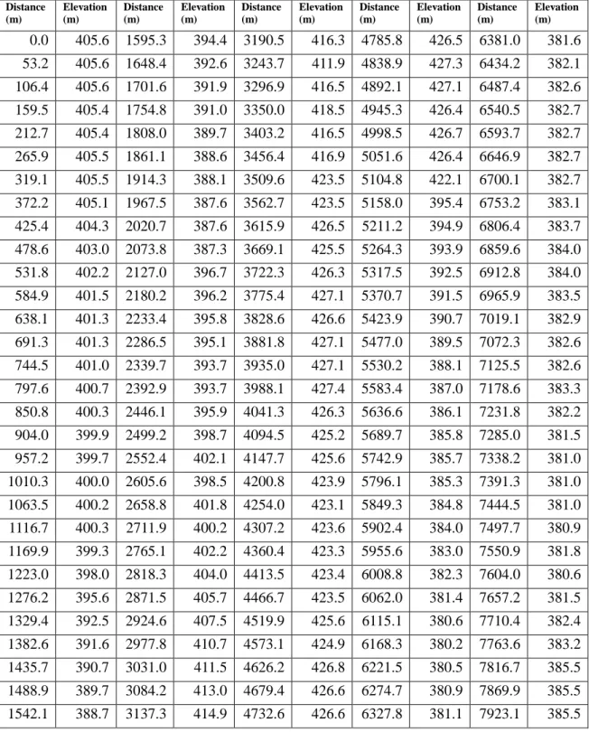
Sample numerical example is conducted based on path profile of microwave link with isolated double edged hilltop shown in Table 1. Microwave frequencies from 1. GHz in the L-band to 36GHz in the Ka-band are considered.
Table 1: The path profiles data for the of microwave links with isolated double edged hilltop
Distance (m)
Elevation (m)
Distance (m)
Elevation (m)
Distance (m)
Elevation (m)
Distance (m)
Elevation (m)
Distance (m)
Elevation (m)
0.0 405.6 1595.3 394.4 3190.5 416.3 4785.8 426.5 6381.0 381.6
53.2 405.6 1648.4 392.6 3243.7 411.9 4838.9 427.3 6434.2 382.1
106.4 405.6 1701.6 391.9 3296.9 416.5 4892.1 427.1 6487.4 382.6
159.5 405.4 1754.8 391.0 3350.0 418.5 4945.3 426.4 6540.5 382.7
212.7 405.4 1808.0 389.7 3403.2 416.5 4998.5 426.7 6593.7 382.7
265.9 405.5 1861.1 388.6 3456.4 416.9 5051.6 426.4 6646.9 382.7
319.1 405.5 1914.3 388.1 3509.6 423.5 5104.8 422.1 6700.1 382.7
372.2 405.1 1967.5 387.6 3562.7 423.5 5158.0 395.4 6753.2 383.1
425.4 404.3 2020.7 387.6 3615.9 426.5 5211.2 394.9 6806.4 383.7
478.6 403.0 2073.8 387.3 3669.1 425.5 5264.3 393.9 6859.6 384.0
531.8 402.2 2127.0 396.7 3722.3 426.3 5317.5 392.5 6912.8 384.0
584.9 401.5 2180.2 396.2 3775.4 427.1 5370.7 391.5 6965.9 383.5
638.1 401.3 2233.4 395.8 3828.6 426.6 5423.9 390.7 7019.1 382.9
691.3 401.3 2286.5 395.1 3881.8 427.1 5477.0 389.5 7072.3 382.6
744.5 401.0 2339.7 393.7 3935.0 427.1 5530.2 388.1 7125.5 382.6
797.6 400.7 2392.9 393.7 3988.1 427.4 5583.4 387.0 7178.6 383.3
850.8 400.3 2446.1 395.9 4041.3 426.3 5636.6 386.1 7231.8 382.2
904.0 399.9 2499.2 398.7 4094.5 425.2 5689.7 385.8 7285.0 381.5
957.2 399.7 2552.4 402.1 4147.7 425.6 5742.9 385.7 7338.2 381.0
1010.3 400.0 2605.6 398.5 4200.8 423.9 5796.1 385.3 7391.3 381.0
1063.5 400.2 2658.8 401.8 4254.0 423.1 5849.3 384.8 7444.5 381.0
1116.7 400.3 2711.9 400.2 4307.2 423.6 5902.4 384.0 7497.7 380.9
1169.9 399.3 2765.1 402.2 4360.4 423.3 5955.6 383.0 7550.9 381.8
1223.0 398.0 2818.3 404.0 4413.5 423.4 6008.8 382.3 7604.0 380.6
1276.2 395.6 2871.5 405.7 4466.7 423.5 6062.0 381.4 7657.2 381.5
1329.4 392.5 2924.6 407.5 4519.9 425.6 6115.1 380.6 7710.4 382.4
1382.6 391.6 2977.8 410.7 4573.1 424.9 6168.3 380.2 7763.6 383.2
1435.7 390.7 3031.0 411.5 4626.2 426.8 6221.5 380.5 7816.7 385.5
1488.9 389.7 3084.2 413.0 4679.4 426.6 6274.7 380.9 7869.9 385.5
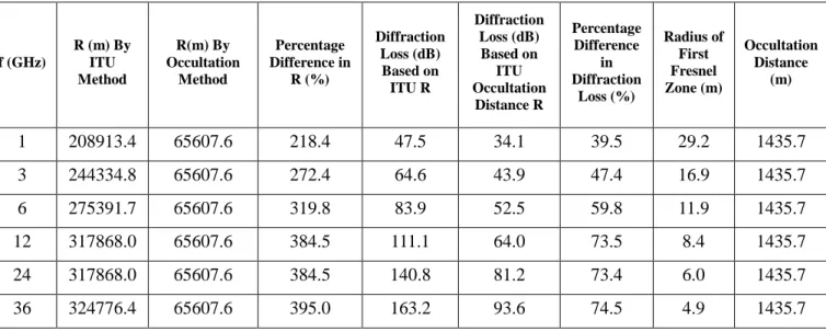
Table 2 shows the diffraction loss, radius of curvature and radius of Fresnel zone for different frequencies and radius of curvature methods. According to the results in Table 2, the rounded edge diffraction computed based on the ITU-R P.526-13 radius of curvature is much higher than the one computed with the occultation distance based radius of curvature. At frequency of 1 GHz , the percentage difference in diffraction loss (%) is about 29% and the difference increases with frequency to as high as 74.5% at 36 GHz.
Similarly, the ITU-R P.526-13 radius of curvature is extremely higher than the occultation distance based radius of curvature. At frequency of 1 GHz , the percentage difference in radius of curvature (%) is about 218% and the difference increases with frequency to as high as 395% at 36 GHz. In all the frequencies considered, the occultation distance remained constant at 1435.7 m.
Table 2: The diffraction loss, radius of curvature and radius of Fresnel zone for different frequencies and radius of curvature methods
f (GHz)
R (m) By ITU Method R(m) By Occultation Method Percentage Difference in R (%) Diffraction Loss (dB) Based on ITU R Diffraction Loss (dB) Based on ITU Occultation Distance R Percentage Difference in Diffraction Loss (%) Radius of First Fresnel Zone (m) Occultation Distance (m)
1 208913.4 65607.6 218.4 47.5 34.1 39.5 29.2 1435.7
3 244334.8 65607.6 272.4 64.6 43.9 47.4 16.9 1435.7
6 275391.7 65607.6 319.8 83.9 52.5 59.8 11.9 1435.7
12 317868.0 65607.6 384.5 111.1 64.0 73.5 8.4 1435.7
24 317868.0 65607.6 384.5 140.8 81.2 73.4 6.0 1435.7
36 324776.4 65607.6 395.0 163.2 93.6 74.5 4.9 1435.7
4. Conclusions
The effect of radius of curvature on the rounded edge diffraction loss computed by the ITU-R P.526-13 rounded edge diffraction loss method is presented. The radius of curvature is computed using two methods , namely, the ITU-R P.526-13 method and the occultation distance-based method. The path profile considered in the study is a double edged hilltop obstruction.The results show that the rounded edge diffraction loss computed by the ITU 526 -13 method is significantly affected by the radius of curvature. Also, for high occultation distance obstructions, the difference in the radius of curvature of the rounded edge and hence on the diffraction loss obtained can be very high. The result therefore shows that the ITU 526 radius of curvature method should be reviewed to ascertain the specific conditions it can be employed.
References
[1] Pradhan, C., & Murthy, G. R. (2015). Analysis of path loss mitigation through dynamic spectrum access: Software defined radio. In Microwave, Optical and Communication Engineering (ICMOCE), 2015 International Conference on , 110-113.
Networks (ICUFN), 2015 Seventh International Conference on , 935-937.
[3] Sasaki, M., Inomata, M., Yamada, W., Kita, N., Onizawa, T., Nakatsugawa, M. (2016). Channel Model Considering Frequency Dependency Based on Propagation Measurements with Multiple Frequencies for 5G Systems, European Wireless 2016; 22th European Wireless Conference; Proceedings of, 1-6.
[4] Conway, M. J., Payne, C. J., Bilén, S. G., & Koski, E. N. (2015). Ground-wave propagation characterization and prediction for HF cognitive radio. In Military Communications Conference, MILCOM 2015-2015 IEEE, 1643-1649.
[5] Han, T., Kuang, Z., Wang, H., & Li, X. (2015). Study on the multiple diffraction for UWB signals under NLOS environment in WSNs. In 2015 International Conference on Intelligent Systems Research and Mechatronics Engineering. Atlantis Press.
[6] Neskovic, A., Neskovic, N., & Paunovic, G. (2000). Modern approaches in modeling of mobile radio systems propagation environment. IEEE Communications Surveys & Tutorials, 3(3), 2-12.
[7] Goldsmith, A. (2005). Wireless communications. Cambridge University Press.
[8] Yarkony, N., & Blaunstein, N. (2007). Prediction of propagation charachteresitics in indoor radio communication environments. In Antennas and Propagation, 2007. EuCAP 2007. The Second European Conference on, 1-9.
[9] Lee, W. C. Y., & Lee, J. Y. (2000). U.S. Patent No. 6,032,105. Washington, DC: U.S. Patent and Trademark Office.
[10] Bassey, D. E., Okoro, R. C., & Okon, B. E. (2016). Issues Associated with Decimeter Waves Propagation at 0.6, 1.0 and 2.0 Peak Fresnel Zone Levels. International Journal of Science and Research, 5(2), 159-163.
[11] Munilla Diez, M. (2016). Derive a methodology for the design of a broadband (over 1 Gbps) microwave backhaul link in E-band,
http://hdl.handle.net/10902/8446.
[12] Djinevski, L., Filiposka, S., Mishkovski, I., & Trajanov, D. (2015). Accelerating Wireless Network Simulation in 3D Terrain Using GPUs. Adhoc & Sensor Wireless Networks, 29, 253-264.
[13] Blakaj, V., & Gashi, G. (2014). Implementation of a 3D terrain-dependent Wave Propagation Model in WRAP, diva2:744430.
[14] Taylor, J. E. (2016). Lidar heat map based channel sounding for complex wireless environments (Doctoral dissertation, Queensland University of Technology).
[15] Tabakcioglu, M. B. (2016). S-UTD-CH model in multiple diffractions. International Journal of Electronics, 103(5), 765-774.
[16] Jude, O. O., Jimoh, A. J., & Eunice, A. B. (2016). Software for Fresnel-Kirchoff Single Knife-Edge Diffraction Loss Model. Mathematical and Software Engineering, 2(2), 76-84.
[17] Ghasemi, A., Abedi, A., & Ghasemi, F. (2012). Propagation engineering in wireless communications. Berlin: Springer.
[18] Baldassaro, P. M. (2001). RF and GIS: Field Strength Prediction for Frequencies between 900 MHz and 28 GHz (Doctoral dissertation, Virginia Tech).
Technology).
[20] Gálvez, A. M. (2009) Calculation of the coverage area of mobile broadband communications. Focus on land. Master’s Thesis Norwegian University of Science and Technology Department of Electronics and Telecommunications. [21] Pollock, P. (2001). A Model to Predict Diffraction Attentuation Resulting from
Signal Propagation Over Terrain in Low Earth Orbit Satellite Systems (No.
AFIT/GSO/ENG/01M-01). AIR FORCE INST OF TECH
WRIGHT-PATTERSON AFB OH SCHOOL OF ENGINEERING AND MANAGEMENT.
[22] InternationalTelecommunication Union, “RecommendationITU-RP.526-13: “Propagation by diffraction”, Geneva, 2013.
[23] Joo, J., Han, D. S., & Jeong, H. J. (2015, October). First Fresnel zone analysis in vehicle-to-vehicle communications. In Connected Vehicles and Expo (ICCVE), 2015 International Conference on , 196-197.
[24] Bassey, D. E., Akpan, A. O., & Udoeno, E. (2016). UHF Wave Propagation Losses Beyond 40 Percent Fresnel Zone Radius in South-South, Nigeria. International Journal of Science and Research (IJSR), 5(2), 470-475. [25] Rad, P. B., Gajewski, D., & Vanelle, C. (2016). Diffraction Separation Based on
the Projected First Fresnel Zone. 78th EAGE Conference and Exhibition 2016. [26] Seybold, J. S. (2005). Introduction to RF propagation. John Wiley & Sons.
[27] Barué, G. (2008). Microwave engineering: land & space radiocommunications (Vol. 9). John Wiley & Sons.
![Figure 3: The Geometry of the Vertical Profile of the obstruction used for the determination of the radius of the rounded edge fitted to the vicinity of the obstruction vertex according to ITU Method [22]](https://thumb-us.123doks.com/thumbv2/123dok_us/7949222.2112418/5.892.212.723.449.726/geometry-vertical-profile-obstruction-determination-vicinity-obstruction-according.webp)