™
WARNING
This manual contains information on limitations regarding product use and
function and information on the limitations as to liability of the manufacturer. The entire manual should
be carefully read.
NT9010
v 1.0
Installation
Guide
Limited Warranty
Digital Security Controls Ltd. warrants the original purchaser that for a period of twelve months from the date of purchase, the product shall be free of defects in materials and workmanship under normal use. During the warranty period, Digital Security Controls Ltd. shall, at its option, repair or replace any defective product upon return of the product to its factory, at no charge for labour and materials. Any replacement and/or repaired parts are warranted for the remainder of the original warranty or ninety (90) days, whichever is longer. The original owner must promptly notify Digital Security Controls Ltd. in writing that there is defect in material or workmanship, such written notice to be received in all events prior to expiration of the warranty period.
I n t e rn a t i o n a l Wa r r a n t y
The warranty for international customers is the same as for any customer within Canada and the United States, with the exception that Digital Security Controls Ltd. shall not be responsible for any customs fees, taxes, or VAT that may be due. Wa r r a n t y P ro c e d u re
To obtain service under this warranty, please return the item(s) in question to the point of purchase. All authorized distributors and dealers have a warranty pro-gram. Anyone returning goods to Digital Security Controls Ltd. must first obtain an authorization number. Digital Security Controls Ltd. will not accept any ship-ment whatsoever for which prior authorization has not been obtained. C o n d i t i o n s t o Vo i d Wa r r a n t y
This warranty applies only to defects in parts and workmanship relating to normal use. It does not cover:
•damage incurred in shipping or handling;
•damage caused by disaster such as fire, flood, wind, earthquake or lightning; •damage due to causes beyond the control of Digital Security Controls Ltd. such as excessive voltage, mechanical shock or water damage;
•damage caused by unauthorized attachment, alterations, modifications or foreign objects;
•damage caused by peripherals (unless such peripherals were supplied by Digital Security Controls Ltd.);
•defects caused by failure to provide a suitable installation environment for the products;
•damage caused by use of the products for purposes other than those for which it was designed;
•damage from improper maintenance;
•damage arising out of any other abuse, mishandling or improper application of the products.
Digital Security Controls Ltd.’s liability for failure to repair the product under this warranty after a reasonable number of attempts will be limited to a replacement of the product, as the exclusive remedy for breach of warranty. Under no
circum-stances shall Digital Security Controls Ltd. be liable for any special, incidental, or consequential damages based upon breach of warranty, breach of contract, negli-gence, strict liability, or any other legal theory. Such damages include, but are not limited to, loss of profits, loss of the product or any associated equipment, cost of capital, cost of substitute or replacement equipment, facilities or services, down time, purchaser’s time, the claims of third parties, including customers, and injury to property.
D i s c l a i m e r o f Wa r r a n t i e s
This warranty contains the entire warranty and shall be in lieu of any and all other warranties, whether expressed or implied (including all implied warranties of merchantability or fitness for a particular purpose) And of all other obligations or liabilities on the part of Digital Security Controls Ltd. Digital Security Controls Ltd. neither assumes nor authorizes any other person purporting to act on its behalf to modify or to change this warranty, nor to assume for it any other war-ranty or liability concerning this product.
This disclaimer of warranties and limited warranty are governed by the laws of the province of Ontario, Canada.
WARNING: Digital Security Controls Ltd. recommends that the entire system be completely tested on a regular basis. However, despite frequent testing, and due to, but not limited to, criminal tampering or electrical disruption, it is possible for this product to fail to perform as expected.
I n s t a l l e r ’s L o c ko u t
Any products returned to DSC which have the Installer’s Lockout option enabled and exhibit no other problems will be subject to a service charge.
O u t o f Wa r r a n t y R e p a i r s
Digital Security Controls Ltd. will at its option repair or replace out-of-warranty products which are returned to its factory according to the following conditions. Anyone returning goods to Digital Security Controls Ltd. must first obtain an authorization number. Digital Security Controls Ltd. will not accept any shipment whatsoever for which prior authorization has not been obtained.
Products which Digital Security Controls Ltd. determines to be repairable will be repaired and returned. A set fee which Digital Security Controls Ltd. has predeter-mined and which may be revised from time to time, will be charged for each unit repaired.
Products which Digital Security Controls Ltd. determines not to be repairable will be replaced by the nearest equivalent product available at that time. The current market price of the replacement product will be charged for each replacement unit.
Ta b l e o f C o n t e n t s
Chapter 1: Quick Set Up
Section 1.1: Introduction
1.1.1 About the NT9010 System ... 1
1.1.2 About the NT9010 Manual Set ... 1
1.1.3 Main system Specifications ... 2
1.1.4 Additional Devices ... 3
1.1.5 Peel-off Instruction Labels ... 4
Section 1.2: Installing The NT9010 1.2.1 Out of the Box ... 5
1.2.2 Create an Installation Plan ... 5
1.2.3 Prepare the Mounting Location ... 5
1.2.4 Installing the NT9010 ... 5
1.2.5 Connecting the Battery ... 6
1.2.6 Mounting the Wireless Devices ... 10
1.2.7 Enrolling Devices and Setting Up the System .... 10
1.2.8 Other NT9010 Options ... 13
1.2.9 Deleting Wireless Devices ... 13
Section 1.3: Troubleshooting 1.3.1 Typical Installation Problems and Solutions ... 14
Chapter 2: Advanced Programming
Section 2.1: Programming the NT9010 2.1.1 How to Enter Advanced Programming ... 152.1.2 Programming Decimal Data ... 15
2.1.3 Programming Hexadecimal Data ... 16
2.1.4 Programming Toggle Options ... 16
2.1.5 Programming Audio Labels ... 16
2.1.6 Reviewing Programming ... 18
2.1.7 Exiting Programming ... 18
Section 2.2: Changing How the NT9010 Works For Users 2.2.1 Accessing the NT9010 System Using a Telephone 19 2.2.2 Access Codes ... 20
2.2.3 Voice Prompt Interface ... 22
2.2.4 Alarm Announce-ments ... 23
2.2.5 Arming and Disarming Options ... 24
2.2.6 Automatic Arming ... 25
2.2.7 Entry and Exit Delay Options ... 25
2.2.8 Bell Options ... 26
2.2.9 User Commands ... 27
2.2.10 Function Keys ... 31
2.2.11 Programming Wireless Keys ... 33
2.2.12 Fire, Auxiliary, and Panic Keys ... 33
2.2.13 Keypad Options ... 34
2.2.14 Sleep Mode ... 35
Section 2.3: Changing Other NT9010 Functions 2.3.1 Zone Definitions ... 36
2.3.2 Zone Attributes ... 38
2.3.3 Enrolling Hardwired Zones ... 39
2.3.4 Wireless Device Serial Numbers ... 39
2.3.5 Wireless Zone Supervision ... 40
2.3.6 RF Jamming Detection Zone ... 40
2.3.7 Zone Tamper/Fault Options ... 41
2.3.8 Communicator Dialing ... 41
2.3.9 Communicator Telephone Numbers ... 43
2.3.10 Communicator Account Codes ... 44
2.3.11 Communicator Reporting Formats ... 44
2.3.12 CommunicatorReporting Codes ... 47
2.3.13 Talk/Listen-in Programming ... 49
2.3.14 Downloading ... 51
2.3.15 Telephone Line Monitoring (TLM) ... 53
2.3.16 Test Transmissions ... 53
2.3.17 Event Buffer ... 54
2.3.18 Swinger Shutdown ... 54
2.3.19 Timebase ... 54
2.3.20 Factory Default ... 54
2.3.21 Installer Lockout ... 55
2.3.22 Walk Test ... 56 Appendix A: Guidelines for Locating Smoke
Detectors 57
Appendix B: Reporting Codes 58
Appendix C: WLS925L-433 Mini Door/
Window Contact Installation Instructions 61 Appendix D: WLS904P Wireless Motion Detector Installation Instructions 62
WARNING
Please Read CarefullyN o t e t o I n s t a l l e r s
This warning contains vital information. As the only individual in contact with sys-tem users, it is your responsibility to bring each isys-tem in this warning to the attention of the users of this system.
S y s t e m Fa i l u r e s
This system has been carefully designed to be as effective as possible. There are cir-cumstances, however, involving fire, burglary, or other types of emergencies where it may not provide protection. Any alarm system of any type may be compromised deliberately or may fail to operate as expected for a variety of reasons. Some but not all of these reasons may be:
■
Inadequate InstallationA security system must be installed properly in order to provide adequate protec-tion. Every installation should be evaluated by a security professional to ensure that all access points and areas are covered. Locks and latches on windows and doors must be secure and operate as intended. Windows, doors, walls, ceilings and other building materials must be of sufficient strength and construction to provide the level of protection expected. A reevaluation must be done during and after any con-struction activity. An evaluation by the fire and/or police department is highly rec-ommended if this service is available.
■ Criminal Knowledge
This system contains security features which were known to be effective at the time of manufacture. It is possible for persons with criminal intent to develop techniques which reduce the effectiveness of these features. It is important that a security sys-tem be reviewed periodically to ensure that its features remain effective and that it be updated or replaced if it is found that it does not provide the protection expected.
■ Access by Intruders
Intruders may enter through an unprotected access point, circumvent a sensing device, evade detection by moving through an area of insufficient coverage, discon-nect a warning device, or interfere with or prevent the proper operation of the sys-tem.
■ Power Failure
Control units, intrusion detectors, smoke detectors and many other security devices require an adequate power supply for proper operation. If a device operates from batteries, it is possible for the batteries to fail. Even if the batteries have not failed, they must be charged, in good condition and installed correctly. If a device operates only by AC power, any interruption, however brief, will render that device inopera-tive while it does not have power. Power interruptions of any length are often accompanied by voltage fluctuations which may damage electronic equipment such as a security system. After a power interruption has occurred, immediately conduct a complete system test to ensure that the system operates as intended.
■ Failure of Replaceable Batteries
This system’s wireless transmitters have been designed to provide several years of battery life under normal conditions. The expected battery life is a function of the device environment, usage and type. Ambient conditions such as high humidity, high or low temperatures, or large temperature fluctuations may reduce the expected battery life. While each transmitting device has a low battery monitor which identifies when the batteries need to be replaced, this monitor may fail to operate as expected. Regular testing and maintenance will keep the system in good operating condition.
■ Compromise of Radio Frequency (Wireless) Devices
Signals may not reach the receiver under all circumstances which could include metal objects placed on or near the radio path or deliberate jamming or other inad-vertent radio signal interference.
■ System Users
A user may not be able to operate a panic or emergency switch possibly due to per-manent or temporary physical disability, inability to reach the device in time, or unfamiliarity with the correct operation. It is important that all system users be trained in the correct operation of the alarm system and that they know how to respond when the system indicates an alarm.
■ Smoke Detectors
Smoke detectors that are a part of this system may not properly alert occupants of a fire for a number of reasons, some of which follow. The smoke detectors may have been improperly installed or positioned. Smoke may not be able to reach the smoke detectors, such as when the fire is in a chimney, walls or roofs, or on the other side
of closed doors. Smoke detectors may not detect smoke from fires on another level of the residence or building.
Every fire is different in the amount of smoke produced and the rate of burning. Smoke detectors cannot sense all types of fires equally well. Smoke detectors may not provide timely warning of fires caused by carelessness or safety hazards such as smoking in bed, violent explosions, escaping gas, improper storage of flammable materials, overloaded electrical circuits, children playing with matches or arson. Even if the smoke detector operates as intended, there may be circumstances when there is insufficient warning to allow all occupants to escape in time to avoid injury or death.
■ Motion Detectors
Motion detectors can only detect motion within the designated areas as shown in their respective installation instructions. They cannot discriminate between intrud-ers and intended occupants. Motion detectors do not provide volumetric area pro-tection. They have multiple beams of detection and motion can only be detected in unobstructed areas covered by these beams. They cannot detect motion which occurs behind walls, ceilings, floor, closed doors, glass partitions, glass doors or windows. Any type of tampering whether intentional or unintentional such as masking, painting, or spraying of any material on the lenses, mirrors, windows or any other part of the detection system will impair its proper operation. Passive infrared motion detectors operate by sensing changes in temperature. How-ever their effectiveness can be reduced when the ambient temperature rises near or above body temperature or if there are intentional or unintentional sources of heat in or near the detection area. Some of these heat sources could be heaters, radiators, stoves, barbeques, fireplaces, sunlight, steam vents, lighting and so on.
■ Warning Devices
Warning devices such as sirens, bells, horns, or strobes may not warn people or waken someone sleeping if there is an intervening wall or door. If warning devices are located on a different level of the residence or premise, then it is less likely that the occupants will be alerted or awakened. Audible warning devices may be inter-fered with by other noise sources such as stereos, radios, televisions, air condition-ers or other appliances, or passing traffic. Audible warning devices, however loud, may not be heard by a hearing-impaired person.
■ Telephone Lines
If telephone lines are used to transmit alarms, they may be out of service or busy for certain periods of time. Also an intruder may cut the telephone line or defeat its operation by more sophisticated means which may be difficult to detect.
■ Insufficient Time
There may be circumstances when the system will operate as intended, yet the occupants will not be protected from the emergency due to their inability to respond to the warnings in a timely manner. If the system is monitored, the response may not occur in time to protect the occupants or their belongings.
■ Component Failure
Although every effort has been made to make this system as reliable as possible, the system may fail to function as intended due to the failure of a component.
■ Inadequate Testing
Most problems that would prevent an alarm system from operating as intended can be found by regular testing and maintenance. The complete system should be tested weekly and immediately after a break-in, an attempted break-in, a fire, a storm, an earthquake, an accident, or any kind of construction activity inside or outside the premises. The testing should include all sensing devices, keypads, consoles, alarm indicating devices and any other operational devices that are part of the system.
■ Security and Insurance
Regardless of its capabilities, an alarm system is not a substitute for property or life insurance. An alarm system also is not a substitute for property owners, renters, or other occupants to act prudently to prevent or minimize the harmful effects of an emergency situation.
Chapter 1: Quick Set Up
Section 1.1: Introduction
1.1.1 About the NT9010 System
The NT9010 is a full-featured, wireless security system. It has been designed for fast and easy installation.
The NT9010 system is made up of the following components: • A main control unit
• Up to 32 wireless detectors and panic pendants (total) • You can also add up to 16 wireless keys.
The NT9010 system supports up to 32 zones (detectors and panic pendants), and 32 system users. The NT9010 main control unit guides users through their available options with easy-to-understand audio prompts. The status of the NT9010 system can be monitored over a telephone line.
You can program the system using the keypad on the NT9010 control unit, or using DLS-3 downloading software and a computer. If you program the system from the NT9010 control unit, you can do the basic zone enrollment and programming using Flash Programming. See Chapter 1: Quick Set Up in the Installation Guide for more information on using Flash Programming.
1.1.2 About the NT9010 Manual Set
The NT9010 system has three manuals, Installation Guide, Programming Work-sheets, and User’s guide.
☛ Installation Guide
The Installation Guide contains two main chapters. Chapter 1: Quick Set Up
This chapter is for people who will be installing NT9010 systems requiring only basic programming. This will be the case in the majority of installations. Please review this chapter before beginning your installation. The Quick Set Up covers the following topics:
• An overview of the system
• How to mount and complete NT9010 wiring
• How to enroll devices and program the system using Flash Programming • Basic troubleshooting tips
• Guidelines for placing smoke detectors Chapter 2: Advanced Programming
This chapter is for people who will be installing a system that needs special features or custom programming. If your installation requires more programming than is included in Flash Programming, review the relevant sections of this chapter for more information.
C h a p t e r 1 : Q u i c k S e t U p
☛ Programming Worksheets
This manual is used to record your zone choices and other programming for the system.
NOTE: Keep this manual in a safe place for future reference.
☛ User’s Guide
The User’s Guide provides easy to follow instructions for NT9010 users. This Guide contains instructions on turning the system on or off, dealing with alarms and emergencies, using advanced functions, fire safety, and how to replace wireless device batteries.
Installers should also review this manual, in order to properly instruct the end-users once the installation is complete.
1.1.3 Main system Specifications
Flexible Zone Configuration: • 32 fully programmable zones
• 23 zone types, 8 programmable zone options • Connect up to 2 hardwired zones
Access Codes:
• 38 access codes: 32 user codes, 1 Master code, 2 supervisor codes, 2 duress codes, and 1 maintenance code
Remote Sounder Output:
• Four-wire supervised connection to optional remote sounder
• Can be wired up to 500ft (152m), 22AWG from the NT9010 control unit • Capable of steady or pulsed siren, voice prompts, and central station
talk/listen-in sessions EEPROM Memory:
• Will not lose programming or system status on complete AC and battery failure Power Requirements:
• Plug-in transformer = 9VAC, 20VA (use only DSC transformer PTD920) • Battery = 6 volt 3.5 Ah rechargeable sealed lead acid (use only DSC battery
BD3.5-6V)
Digital Communicator Specifications:
• Supports all major formats including SIA, Contact ID, and 20bps formats • Split reporting of selected transmissions to each telephone number • 3 programmable telephone numbers
• 2 system account codes • DTMF and pulse dialing • DPDT line seizure • Anti-jam detection
S ec ti o n 1 . 1 : I n tr o d u c t i o n System Supervision Features
The NT9010 continuously monitors a number of possible trouble conditions includ-ing:
• AC power failure (system enters “Sleep” mode on loss of AC power for longer than 30 seconds)
• Trouble by zone • Fire trouble
• Telephone line trouble • Low battery condition • Remote sounder supervisory • Loss of internal clock • Tamper by zone • Failure to communicate • Improper zone placement
False Alarm Prevention Features • Audible exit delay
• Audible exit fault • Urgency on entry delay • Quick exit
• Swinger shutdown • Recent closing transmission • Communication delay • Rotating keypress buffer Additional Features
• Keypad activated alarm output and communicator test • Keypad lockout
• 128 event buffer, time and date stamped • Uploading/downloading capability
1.1.4 Additional Devices
WLS904-433 Wireless Motion Detector
The wireless motion detector can be used to provide wireless interior protection. The unit comes with four AAA batteries.
WLS904P-433 Wireless Motion Detector with Pet Immunity
The wireless motion detector can be used to provide wireless interior protection. The unit comes with four AAA batteries.
WLS906-433 Wireless Smoke Detector
The wireless smoke detector can be used to provide wireless smoke detection. The unit comes with six AA batteries.
C h a p t e r 1 : Q u i c k S e t U p
WLS912-433 Wireless Glassbreak Detector
The wireless glassbreak detector can be used to provide wireless glassbreak detec-tion. The unit comes with three AA batteries.
WLS914-433 Dual PIR Wireless Motion Detector
The dual PIR wireless motion detector can be used to provide wireless space protec-tion. The unit comes with four AA batteries.
WLS925L-433 Mini Wireless Universal Transmitter
The WLS925L-433 wireless universal transmitter is a smaller transmitter that can be used for door and window contacts. The unit comes with one Lithium battery and has built-in contacts.
WLS929-433 Wireless Key
The wireless key can be used to provide a simple and mobile method of arming and disarming the system. The unit comes with three Photo/Electronic 1.5V batteries. This system can have a maximum of 16 Wireless Keys.
NT9201 Remote Sounder
You can connect a hardwired remote sounder to the NT9010 system. This sounder provides an additional station for the NT9010 to sound alarms and system status, and for central station talk/listen-in sessions.
NOTE: Maximum distance for the Remote Sounder is 500ft (152m) using 22AWG sheilded cable.
1.1.5 Peel-off Instruction Labels
The Envoy unit comes with a set of peel-off instruction labels already applied. Installer should remove these labels after installation. For future programming needs, please see sample labels below for instructions.
The NT9010's "Flash" programming will help you to quickly set up the system. To begin:
1. Press [ ][8]
2. Enter the default installer’s code: [5555] 3. Follow the audio instruction
buttons [A] to [F] for entering letters in serial numbers.
✱
For contacts used on the hardwired zones: Enter serial number 200001 for the first hardwired zone Enter serial number 200002 for the second hardwired zone. Use
! !
1 = YES
2 = NO
Selection Type 2 (TX) Type 3 (PIR) Type 4 (Smoke)
[A] Preset Front Door Main Floor Motion Main Floor Fire [B] Preset Back Door Upstairs Motion Upstairs Fire [C] Preset Garage Door Downstairs Motion Downstairs Fire [D] Preset Window Hallway Motion Hallway Fire [E] Preset Patio Door Garage Motion Garage Fire Please usebuttons [A] to [E] for standard label options
ALSO REFER TO INSTALLATION MANUAL PEELOFF A
B
C D E F Back Forward
PEELOFF
A = Stay B = Away C = Chime D = Exit E = Status F = Volume Back = Record Forward = Playback
Section 1.2: Installing The NT9010
Please read this section to get an overall understanding of the steps involved in installing the NT9010 system. Carefully work through each step. This will help to reduce problems and to reduce the overall installation time required.
1.2.1 Out of the Box
Check that the following parts are included in your NT9010 package: • NT9010 main control unit and backup battery
• Two WLS925L-433 transmitters
• One WLS904P-433 motion detector with pet immunity • One 9V, 20VA plug-in transformer
• One set of Installation, Programming Worksheets and User manuals • Two 5600Ω resistors
• 4 mounting screws
1.2.2 Create an Installation Plan
Draw a rough sketch of the building. Find good locations for the NT9010 control unit and all the detectors. Here are some guidelines for choosing good mounting locations.
Choosing a NT9010 Mounting Location
Before you mount the NT9010, you should find a place that is: • Dry
• Far from sources of interference, including:
■ electrical noise such as computers, televisions and electric motors in
appli-ances and heating and air conditioning units.
■ large metal objects like heating ducts and plumbing which may shield the
antenna.
Choosing Mounting Locations for Wireless Devices
Each type of wireless device has its own set of guidelines for mounting locations. Before deciding on mounting locations, make sure that you review the guidelines in the Installation Instructions that come with each device.
1.2.3 Prepare the Mounting Location
Once you have selected a suitable place for the NT9010 control unit, make sure that you will be able to connect the AC power and the telephone line to the NT9010. If necessary, have an electrician route AC wiring to the mounting location, and have a telephone installer route the incoming telephone line to the mounting location.
1.2.4 Installing the NT9010
Mounting the NT9010 Backplate
The NT9010 backplate is the blue-grey piece of plastic that comes attached to the back of the NT9010 control unit. This is the mounting plate for the NT9010 unit. It also provides terminals for connecting the wiring to the NT9010.
C h a p t e r 1 : Q u i c k S e t U p
NOTE: Complete all wiring before applying AC power.
To remove the backplate from the NT9010:
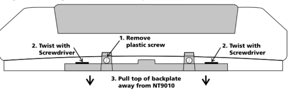
1. Remove the plastic screw from the top of the NT9010 unit (see Figure 1). Keep the screw in a safe location so that you can replace it later.
2. Insert a flathead screwdriver in the slots shown in Figure 1. Twist the screwdriver so that the backplate separates from the plastic housing.
3. Pull the top of the backplate away from the NT9010. 4. Unhook the backplate from the bottom of the NT9010. Now you can attach the backplate to the wall:
1. Pull the prepared AC and telephone wires through the square hole in the back-plate.
2. Place the backplate on the wall in the selected mounting location, and mark the screw locations.
3. Using wall anchors for all screw locations, secure the backplate to the wall.
1.2.5 Connecting the Battery
Before you attach the NT9010 to the backplate, you must connect the battery. The battery is used to provide backup power in the event of an AC power failure and to provide additional current when necessary, such as when the system is in alarm.
NOTE: Place the unit face down before removing the plastic. 1. Remove the two metal screws at the back of the NT9010. 2. Remove the back plastic from the NT9010.
3. Connect the RED battery lead to the positive (+) terminal of the battery, the BLACK battery lead to the negative (-) terminal.
4. Replace the back plastic on the NT9010 and secure it with the metal screws.
NOTE: The unit will not power up if only the battery is connected. AC power must also be connected to the NT9010.
Figure 1: Removing NT9010 Wall-Mount Backplate
1. Remove plastic screw 2. Twist with
Screwdriver
2. Twist with Screwdriver
3. Pull top of backplate away from NT9010
Se c t i o n 1 . 2 : I n s ta l l i n g Th e N T 9 01 0 Connecting AC and Telephone Wiring
Connect the AC and telephone line wiring to the terminals mounted on the NT9010 back-plate. When you later attach the NT9010 to the backplate, the posts on the back of the unit will plug into the terminals, completing the connection.
AC Terminals
For the NT9010 to work correctly, you will need to connect it to an AC power source that is not controlled by a switch. The system comes with a 9V, 20VA plug-in transformer. Connect the transformer to an unswitched AC source and to the two terminals on the back-plate labelled AC.
NOTE: Risk of fire if the rated voltage is not used. Do not power the Envoy controller at a voltage higher than 9V AC. Use only transformer Model PTD920 as supplied with the unit.
NOTE: Do not connect the transformer to a power supply until all other wiring is complete.
NOTE: If you remove power from the unit (AC and battery), you must wait at least 10 seconds before reapplying power.
Telephone Terminals - TIP, RING, T-1, R-1
If a telephone line is required for users to have local or remote telephone access to the system, for central station communication, or for downloading, connect an RJ-31X jack to the R-1, T-1, RING, and TIP terminals on the backplate as shown in Figure 2.
NOTE: Please ensure that all plugs and jacks meet the dimension, toler-ance and metallic plating requirements of the Code of Federal Regulations, Title 47, Part 68, Subpart F. For proper operation there must be no other telephone equipment connected between the control panel and the tele-phone company facilities.
Do not connect the alarm panel communicator to telephone lines intended for use with a FAX machine. These lines may incorporate a voice filter which disconnects the line if anything other than FAX signals are detected, result-ing in incomplete transmissions.
Connecting Zone Wiring – Hardwired
You can connect up to two hardwired zones to the NT9010. For the hardwired zones to work correctly, you must enroll them with the system (see 2.3.3 Enrolling
Hardwired Zones on page 39). For a complete description of the operation of all
zone types, please see 2.3.1 Zone Definitions on page 36.
C h a p t e r 1 : Q u i c k S e t U p
Use the following NT9010 terminals to make your zone connections:
There are two different ways in which zones may be wired, depending on which programming options have been selected. The system can be programmed to supervise nor-mally closed, or Single End of Line loops. Please refer to the following sections to study each type of individually super-vised zone wiring.
Normally Closed (NC) Loops
To enable normally closed loops, programming section [013], option [1] must be ON.
NOTE: This option should only be selected if Normally Closed (NC) devices/contacts are being used.
Normally Closed Loops . . . Section [013], Option [1] Single End Of Line (EOL) Resistors
To enable system detection of single end of line resistors, programming section [013], option [1] must be OFF.
NOTE: This option should be selected if either Normally Closed (NC) or Normally Open (NO) detection devices or contacts are being used.
Se c t i o n 1 . 2 : I n s ta l l i n g Th e N T 9 01 0 Keyswitch Zone Wiring
Zones may be programmed to be used as keyswitch arming zones and must be wired according to the following diagram: For a complete description of how key-switch zones operate, see 2.3.1 Zone
Definitions on page 36.
Connecting the Remote Sounder
You can connect a hardwired remote sounder to the NT9010 system. This sounder provides an additional station for the NT9010 to sound alarms and system status, and for central station talk/listen-in sessions.
Connect the remote sounder to the NT9010 con-trol unit as shown below:
For the sounder to work on the system you must also turn on the Remote Annunciation option. When this option is turned on, the remote sounder will also be supervised.
The Local Annunciation option controls the sounder in the NT9010 control unit. If you turn this option off, there will be no alarms or voice prompts from the NT9010. If both options are on, there will be sound from both the NT9010 and the Remote Sounder.
If there is a Remote Sounder on the system and it does not report a supervisory sig-nal within 30 seconds, a “Service Required” trouble will be generated, and a “Remote Sounder Trouble” event will be logged in the buffer.
See also 2.3.13 Talk/Listen-in Programming on page 49.
Local Annunciation . . . Section [017], Option [4] Remote Annunciation . . . Section [017], Option [5] Attach NT9010 to Backplate
NOTE: Before attaching the backplate, be sure to connect the battery. See 1.2.5 Connecting
the Battery on page 6.
When you have mounted the backplate to the wall, completed the wiring, and connected the battery, you can attach the NT9010 unit to the backplate. 1. Push the bottom of the NT9010 onto the
back-plate posts, as shown at right.
2. Snap the top of the NT9010 onto the top of the backplate, as shown at right.
3. Secure the NT9010 to the backplate by replacing the plastic screw in the top of the NT9010.
WALL
1. Push bottom of NT9010 onto backplate posts
2. Snap top of NT9010 onto top of backplate
C h a p t e r 1 : Q u i c k S e t U p
1.2.6 Mounting the Wireless Devices
Do not permanently mount the wireless devices until you have completed the Placement Tests (see 1.2.7 Enrolling Devices and Setting Up the System on page 10). Once you have a good location for each of the devices, follow the mounting instructions on the Installation Instruction sheet for each device. For WLS904P-433, see Appendix D: WLS904P Wireless Motion Detector
Installa-tion InstrucInstalla-tions on page 62. For WLS925L-433, see Appendix C: WLS925L-433
Mini Door/Window Contact Installation Instructions on page 61.
1.2.7 Enrolling Devices and Setting Up the System
Flash Programming will guide you through the steps needed to set up each zone and basic system programming. If you need to perform more advanced programming for your installation, please see Chapter 2: Advanced Programming on page 15. To access Flash Programming:
1. Press [✱][8].
2. Enter the Installer’s code. The Installer Code is [5555] at default, but should be changed to prevent unauthorized access to programming.
3. Press [1] to enter Flash Programming.
4. Follow the audio instructions announced by Flash Programming. Flash Program-ming will guide you through the following programProgram-ming areas:
■ Device enrollment ■ Zone label assignment
■ Central station telephone number ■ System account code
■ Placement tests of each wireless device
You can use the Forward (Playback) button to advance to the next section in Flash Programming, and the Backward (Record) button to return to the previous section.
5. Be sure to record all the zone serial numbers and your programming choices in the NT9010 Programming Worksheets.
Here are some notes about system programming done through Flash Programming. Zone Definitions
When you enter a serial number for a device into the NT9010 Flash Programming, the unit will analyze the number to determine what kind of device you are enroll-ing. Based on the type of device, the system will make the following programming choices:
Device Type Zone Definition Other Programming Door/window contact
(2XXXXX, including hard-wired contacts entered as 200001 and 200002)
Delay 1 (Type [01]) For hardwired zones (serial numbers 200001 and 200002), Zone Supervision disabled (section [804]) Motion or glassbreak
detector (3XXXXX)
Interior Stay/Away (Type [05])
None Smoke detector
(4XXXXX)
Delayed 24 Hour Fire (Type [87])
None
Se c t i o n 1 . 2 : I n s ta l l i n g Th e N T 9 01 0
NOTE: To ensure that the NT9010 works properly, you should enroll all entry/exit point zones first.
NOTE: PIR’s covering entry points should be zone type [06] Delay Stay/Away
[01] Delay 1 Zone: If this zone is violated when the system is armed (e.g. door or window is opened), the entry delay will begin. The buzzer will sound to warn the user that the system must be disarmed. If the system is not disarmed before the entry delay expires, an alarm will be generated.
[05] Interior Stay/Away Zone: If this type of zone is violated when the system is armed (e.g. the motion detector senses motion), an instant alarm will be generated unless a Delay Zone is violated first. If a Delay Zone is violated first, this zone will also follow the entry delay. The zone will be automatically bypassed under the following condi-tions:
■ the NT9010 is armed in the Stay Mode
■ the NT9010 is armed without entry delay ([✱][9] arming)
■ the NT9010 is armed with an access code and during the exit delay a Delay zone is NOT violated (user does not go through the entry/exit door).
If zones are automatically bypassed, the user can reactivate the zones by entering [✱][1].
[87] Delayed 24 Hour Fire (Wireless): If this zone is violated (e.g. the smoke detector senses smoke), the alarm will immediately sound, but the alarm communication to the central station will be delayed for 30 seconds. If during the 30 second delay the user presses the [#] key, the alarm and communicator will be delayed an additional 90 seconds. This provides time for a user to correct the problem. If after the 90 second delay the zone is still violated the process will begin again: the alarm will sound but the alarm communication will be delayed for 30 seconds.
If the user does not press the [#] key, after 30 seconds the alarm will latch on and the system will communicate a fire alarm to the central station. The alarm will sound until the Bell Cutoff time expires, or until a valid code is entered.
C h a p t e r 1 : Q u i c k S e t U p
Programming Zone Labels
If an enrolled device is a door/window contact, motion detector, glassbreak detec-tor, or smoke detector the system will then prompt you to enter an audio label for the new zone. You can choose from any of the following preset audio labels:
If necessary, you can also program custom labels for the zones through the NT9010 Flash Programming.
1. For door/window contacts, motion detectors, and glassbreak detectors, at the appropriate place in Flash Programming, instead of selecting labels A to E, press function key F.
2. You can now enter up to six pre-programmed words from the Audio Label Library. For each word you want to program, enter a 3-digit code from the Label Library (for a list of labels and codes, see the NT9010 Programming Worksheets, Appendix A). If your label is less than six words, press [#] at the end of the label. 3. If you want to use a recorded label instead of the words available in the Audio
Label Library, enter [244] for the first label entry, then the number of the label [001] to [005]. The recorded label will replace all six words in the section. You will not be able to add additional words to the label. To record a label for a zone, please see section 2.1.5 Programming Audio Labels on page 16. 4. When you have entered the label, the system will recite it. If the label is correct,
press [1]. If the label is not correct, press [2] and repeat steps 1 to 3 to fix the label.
NOTE: You must accept a label to exit this section. If you choose F for a custom label, then you must create your own label using the Audio Label Library and accept it.
NOTE: If you chose one of the audio labels, section [001] to [005] (#3 above) and there is no audio label recorded, the label will default to “zone X” where “X” is the zone number of the device enrolled. When the label is recorded in section [807], [701] to [705] it will be used.
Entering the Central Station Telephone Number
When prompted, enter the telephone number for the central station. The number can be up to 32 digits long. When you program the number, the system automati-cally inserts the hexadecimal digit “D” at the beginning, to tell the system to
con-Press Function
Key:
Door/window contacts (2XXXXX)
Motion or glassbreak
detector (3XXXXX)
Smoke detector (4XXXXX)
A Front door Main floor motion Main floor fire
B Back door Upstairs motion Upstairs fire
C Garage door Downstairs motion Downstairs fire
D Window Hallway motion Hallway fire
Se c t i o n 1 . 2 : I n s ta l l i n g Th e N T 9 01 0 duct a dial tone search before dialing. If necessary, you can enter the following hexadecimal digits in the telephone number:
• HEX B to dial “✱” (function button B “Away”) • HEX C to dial “#” (function button C “Chime”)
• HEX D for an additional dial tone search (function button D “Exit”) • HEX E to insert a 2-second pause (function button E “Status”)
When you have finished entering the telephone number, press [✱]. The system will recite the number back to you.
Entering the Account Code
The system will send the account code to the central station when communicating system events (e.g. Low Battery, Test Transmission). Enter a 4-digit code.
Testing the Placement of Wireless Devices
Each wireless detector must pass three consecutive placement tests before it will work properly on the system. Follow the instructions in Flash Programming to con-duct the tests. The buzzer will squawk once for “Good” placement and three times for “Bad” placement.
If you exit the Placement Test section before all the zones have passed the neces-sary placement tests, a General System Trouble is generated. This trouble can only be cleared by re-entering the Placement Test and testing all of the devices that have not yet passed, or by deleting the serial numbers of the devices that did not pass the test (see 1.2.9 Deleting Wireless Devices on page 13).
NOTE: Deleting or passing the zone through DLS will not clear this trouble.
1.2.8 Other NT9010 Options
After all zones have passed the Placement Test, Flash Programming will move to the advanced programming sections. If you do not need to do more programming, press [#] to exit.
If you need to complete programming not covered by Flash Programming, please
see Chapter 2: Advanced Programming on page 15 . For example, you may
need to change the definitions of one or more zones. This programming is described in 2.3.1 Zone Definitions on page 36.
1.2.9 Deleting Wireless Devices
To remove a wireless device from the system, you will need to use the advanced programming sections.
1. Press [✱][8], then enter the Installer’s code. The default Installer’s code is [5555]. 3. When prompted, press [2] to go to advanced programming.
4. Enter [804], then enter the 2-digit number of the zone you want to delete (01 - 32). The system announces the current serial number for the zone.
5. Program the serial number for the zone as [000000]. The wireless device for the zone will be removed.
NOTE: You may need to remove power from the system and then restore it to clear troubles caused by deleted zones.
Section 1.3: Troubleshooting
1.3.1 Typical Installation Problems and Solutions
When I try a placement test I get no result or “Bad” results. Check the following:
• Are you testing the correct zone?
• Was the correct serial number entered when the device was enrolled?
• Is the device in range of the NT9010? Try testing the device in the same room as the NT9010.
• Are you testing the zone correctly? (See the Installation Instruction sheet for each device for testing instructions.)
• Are the batteries working and installed correctly?
• Are there any large metal objects that may be preventing the signal from reach-ing the NT9010?
The device must be located where at least three “Good” results are obtained. If several devices show “Bad” results, or if wireless keys operate inconsistently, you may need to move the NT9010. See 1.2.2 Create an Installation Plan on page 5 for tips on choosing a mounting location for the NT9010.
The LED on the motion detector does not turn on when I walk in front of the unit.
The LED is for walk test purposes only. See your WLS904-433, WLS904P-433 or WLS914-433 Installation Instruction sheet for walk test instructions.
Chapter 2: Advanced Programming
Section 2.1: Programming the NT9010
The chapter describes how to use advanced programming. For instructions on using Flash Programming, please see Chapter 1: Quick Set Up Guide.
2.1.1 How to Enter Advanced Programming
You can use the Advanced Programming to set all communicator and system options. The Installer Code is [5555] at default, but should be changed to prevent unauthorized access to programming.
Step 1: From any keypad enter [✱][8][Installer Code].
• The System light will flash and the Armed light will turn on to indicate you are in programming
• The NT9010 will announce “To use Flash Programming press 1. To bypass Flash Programming press 2.”
Step 2: To skip Flash Programming and go to the advanced programming sections, press [2].
Step 3: Enter the 3-digit section number you want to program.
• The Armed light will turn off and the Ready light will turn on to indicate the sys-tem is ready for the information for the selected section
• You can use the Forward (Playback) button to go forward through the advanced programming data. The Backward (Record) button will not work in the advanced programming sections, except for sections [301] to [303], and [402]. Step 4: Sections [802], [804], or [807] have 2- or 3-digit sub-sections. To access programming in these sections enter the programming sub-section number.
NOTE: If the section number entered is not valid, the NT9010 will sound an error tone and say the section number that was entered.
Installer Code . . . Section [006]
2.1.2 Programming Decimal Data
When the Ready light is ON the NT9010 is waiting for the information to be pro-grammed for the selected section.
If a digit is entered for each program box in a section the system will automatically exit from the section. It will turn OFF the Ready light and turn the Armed light back ON.
You can also press the [#] key to exit a section before entering data for every box. This is handy if you only need to change the first few program boxes. All other loca-tions in the section will remain unchanged. If the [#] key is pressed the system will turn OFF the Ready light, turn ON the Armed light and exit from the section.
C h a p t e r 2 : A d v a n c e d P r o g r a m m i n g
You can use also the Forward (Playback) button to go forwards through the gramming data. The Backward (Record) button will not work in the advanced pro-gramming sections (except for sections [301] to [303], and section [402]).
2.1.3 Programming Hexadecimal Data
You may need to enter hexadecimal (HEX) digits for some of the programming sec-tions. To program a HEX digit press the function button corresponding to the HEX digit you want to program:
Button Name HEX Digit
Stay A
Away B
Chime C
Exit D
Status E
Volume F
If you enter information into a section and make a mistake, press the [#] key to exit the section. Select that section again and re-enter the information correctly. If you are using a pulse communications format, a decimal zero [0] does not trans-mit. Programming a zero [0] tells the system not to send any pulses for that digit. To make a zero [0] transmit, it must be programmed as a Hexadecimal ‘A’.
2.1.4 Programming Toggle
Options
Some sections contain several toggle options. Refer to the Programming Work-sheets to determine what each option represents. When you enter a toggle option section, the NT9010 recites the numbers of the options that are currently ON. Press the number corresponding to the option to toggle it ON or OFF. Once all the toggle options have been selected correctly press the [#] key to exit the section and save the changes.
2.1.5 Programming Audio Labels
You can program audio labels for the system, and for each of the zones. If you enroll the zones using Flash Programming, you can choose from five pre-set labels for the zone (please see Chapter 1: Quick Set Up).
Alternatively, you can program custom labels using the advanced programming sections. To program or change a label:
1. From Advanced Programming, enter section [807].
2. Enter the 3-digit sub-section number of the label ([601] to [633]). The system announces the section number and then recites the words presently pro-grammed in the label. Each label may have up to six words. The system then prompts:
“Enter three digit word. To exit, press pound”.
3. Enter the 3-digit code for each word you want to program. You can enter up to six words for each label. Please see Appendix A: Audio Label Library on page 27 in Programming Worksheets for a list of the 3-digit codes for each available word. To add numbers to a label, see Adding Numbers to Labels on page 17.
S ec ti o n 2 . 1 : P r o g r a m m i n g th e N T 9 01 0 4. If you want to use a recorded label, in place of the first word of the label enter
[244], then the number of the label [001] to [005]. The recorded label will replace all six words in the section. To record a label, see Recording Custom Labels on page 17.
5. When you have entered the label, the system will recite it. If the label is correct, press [#]. To change the label, repeat steps 1-4, above.
6. Record the new label in the appropriate section of the Programming Work-sheets.
Adding Numbers to Labels
Three special Number Commands are available to allow the system to include a number in the voice label. The number commands allow the system to announce the number in three different modes:
Label 000: Number Command 1, Combined Form. The number will be announced in its full form. For example, the number 401 would be announced as “four hundred and one”.
Label 001: Number Command 2, Ordered Form. The number will be announced in a descriptive form. For example, the number 401 would be announced as “four hundred and first”.
Label 002: Number Command 3, Individual Numbers. Each digit in the number will be announced individually. For example, the number 401 would be announced as “four zero one”.
The number commands take up two of the six available word spaces in a label. In the first space select the type of announcement for the number (Number Com-mand 000, 001 or 002). In the second space program the 3-digit number to be read (from 000 to 999).
NOTE: Because number commands take up 2 label spaces, you cannot program them in the sixth entry spot for a label.
Recording Custom Labels
You can record up to five custom labels for the system and for the zones using pro-gramming sections [701] to [705]. You can use any of these labels for the system or zone labels, instead of the words available in the Audio Label Library. To record a custom label:
1. From Advanced Programming, enter [807]. 2. Enter one of sub-sections [701] to [705]. 3. Press the Record function key on the NT9010.
4. Speak into the NT9010 microphone. Each label can be up to 1.5 seconds long. To stop recording, press [#].
5. When you are finished recording, press the Playback function key. The NT9010 plays your recorded label back to you. To listen to the label again, press Playback again.
6. If you want to re-record the label, press the Record function key again. 7. To record more labels, repeat steps 1 to 5.
C h a p t e r 2 : A d v a n c e d P r o g r a m m i n g
NOTE: If the NT9010 is completely powered down (both AC and battery power are lost), the recorded labels will be lost.
2.1.6 Reviewing Programming
To review the current programming for a section enter the 3-digit section number. The NT9010 will announce the data programmed. If the programming is correct press [#] to exit the section, otherwise enter the correct data.
2.1.7 Exiting Programming
Section 2.2: Changing How the NT9010
Works For Users
Most NT9010 installations will only require basic programming. You can complete the basic programming using the NT9010 Flash Programming (please see Chapter 1: Quick Set Up for more information). The NT9010 User’s Guide provides basic directions for arming and disarming the system, bypassing zones and performing user func-tions. The following sections provide information on how to customize the NT9010 interface for your users, and how to change which options are available to NT9010 users.
2.2.1 Accessing the NT9010 System Using a Telephone
Accessing the NT9010 Using a Local Telephone
To access the NT9010 system using a premise telephone, pick up any local Touch-Tone1 telephone and enter the three digit Telephone Access Code (default [✱✱✱]). The NT9010 will seize the line and announce
“Hello.”
If the Access Code Required for Local Access option is enabled (section [807]-[021] option [02]) the NT9010 will announce:
“Enter your Access Code.”
Enter your four or six-digit system access code. Invalid access codes count towards the Keypad Lockout, if enabled.
You can access the NT9010 using a local telephone, even if the telephone line is disconnected. For this to operate properly, you must enable Telephone Line Mon-itoring on the system (see 2.3.15 Telephone Line Monitoring (TLM) on page 53).
You can change the Telephone Access Code to any 3 digit code using numbers 0 through 9 as well as the [✱] and [#] keys. This access code can only be changed through Advanced Programming.
NOTE: Avoid programming this code as a valid 3 digit area code or tele-phone service. Avoid numbers such as [911], [411], [611] or [0XX]. Do not try to exit this section by pressing [#], it will be accepted as a valid digit. To exit, program all 3 digits of the code or press [Forward].
Telephone Access Code . . . Section [807]-[020] Code Required for Local Access . . . .Section [807]-[021], Option [2] TLM Enable/Disable . . . Section [015], Option [7] Keypad Lockout. . . Section [012] Accessing the NT9010 Using a Remote Telephone
If the Remote Access option (section [807]-[021], option [01]) is enabled users can access the system from any Touch-Tone* telephone in the world.
NOTE: Please pause for 1 second between key presses when enter-ing access codes or commands on a remote phone.
C h a p t e r 2 : A d v a n c e d P r o g r a m m i n g
1. Call the telephone number the NT9010 system is connected to. 2. Let the telephone ring one or two times.
3. Hang up and wait 10 seconds before calling again. The NT9010 will answer after the first or second ring and announce
“Hello.”
4. Enter the 3-digit Telephone Access Code. If this is not entered within 10 sec-onds the NT9010 will hang up. Once the correct code has been entered, the system will prompt,
“Enter your Access Code.”
5. Enter a 4- or 6-digit access code. The NT9010 will begin to announce the status of the system. If you do not enter an access code within 20 seconds, or if you enter it incorrectly 3 times, the NT9010 will hang up. Invalid access codes count towards the Keypad Lockout, if enabled (see 2.2.13 Keypad
Options on page 34).
NOTE: The Maintenance Code can be used to access the system from a remote telephone.
Remote Access Enabled/Disabled . . . Section [807]-[021], Option [1]
2.2.2 Access Codes For instructions on programming access codes, see the NT9010 User’s Guide (Programming Access Codes).
General access codes can arm and disarm the system. When the Code Required for Bypassing option is enabled, users will need to enter a valid access code in order to bypass zones. Individual access codes can have the Zone Bypassing attribute disabled under Access Code Attribute programming, see Programming
Access Code Attributes on page 21.
If the 6-Digit User Access Codes option is enabled, all the access codes may be programmed with six digits instead of four, with the exception of the Panel ID code and the Downloading Access Code. The Installer’s Code will become [555555]. If 4-digit codes are already programmed and this option is selected, the first four 4-digits of the programmed codes will remain as programmed and the last two digits will be [00].
If the 4-Digit User Access Codes is selected, all codes will be 4-Digits in length. If 6-digit codes were previously programmed and this option is enabled, the last two digits of each code will be erased.
The available access codes are as follows:
General Access Codes - Access Codes [01] to [32]
Each access code can be used to arm and disarm the system. Additional access code attributes are also programmable to determine what abilities the code will have.
You can program access code attributes by following the instructions in this sec-tion.
S e c t i o n 2. 2: C h an g i n g H o w t h e N T 90 1 0 W o r k s F o r U s e r s Duress Codes - Access Codes [33] and [34]
When a Duress Code is used to perform any function the system will send a Duress Reporting Code to the central station (see 2.3.12 CommunicatorReporting Codes on page 47).
Master Code - Access Code [40]
The Master Codes can perform any keypad function. These codes can be used to program all access codes, including the Duress Codes.
If the Master Code Not Changeable option is enabled users will not be able to change the Master Code [40]. You will only be able to change it using Advanced Programming.
Supervisor Codes - Access Codes [41] to [42]
Supervisor Codes can program additional access codes. By default, Supervisor codes have the same attribute programming as the Master code. You can change the attribute programming for these codes by following the instructions in this section. Maintenance Code
The maintenance code can only be used to arm and disarm the system. The main-tenance code will also allow remote (telephone) access to the system.
It cannot be used to bypass zones, or for any other function. This code can only be programmed in Advanced Programming.
Installer’s Code
You will use the Installer’s Code to set up and to program the system. The Installer Code is [5555] at default, but should be changed to prevent unauthorized access to programming.
Telephone Access Code
If the NT9010 system is connected to the premise telephone line, users will be able to access their system using a premise or phone (see 2.2.1 Accessing the NT9010
System Using a Telephone on page 19). Users will need to enter a Telephone
Access Code before they can use the NT9010 system. The default Telephone Access Code is [✱✱✱]. You can change this to any 3 digit code using numbers 0 through 9 as well as the [✱] and [#] keys. This access code can only be changed through Advanced Programming.
NOTE: Avoid programming this code as a valid 3 digit area code or tele-phone service. Avoid numbers such as [911], [411], [611] or [0XX]. Do not try to exit this section by pressing [#], it will be accepted as a valid digit. To exit, program all 3 digits of the code or press [Forward].
Programming Access Code Attributes
Attributes determine what abilities an access code will have.
By default, each code has the attributes of the code used to program it. For exam-ple, if you use the Master code to program other access codes, the new codes will have the same attributes as the Master code. You can change the attribute pro-gramming by following the instructions below.
You cannot change Master code attribute programming. The Master code has all attributes turned on, except for the Bell Squawk on Arming/Disarming attribute.
C h a p t e r 2 : A d v a n c e d P r o g r a m m i n g
To program each attribute:
1. Enter [✱][5][Master code][9] to enter the attribute programming mode. 2. Enter the 2-digit number of the access code you want to edit.
3. Enter the attribute number to toggle it on or off. The programmable attributes are as follows:
• Attribute 1: User enabled for arming, disarming, alarm reset, auto-arm cancel (on by default)
• Attribute 2: For future use • Attribute 3: Zone Bypass enabled
This attribute allows the user to bypass zones. • Attribute 4: NT9010 Telephone Access
This attribute allows the user to access the security system from a telephone when an access code is required.
• Attributes 5-6: For future use
• Attribute 7: Bell Squawk on Arming/Disarming. When this attribute is turned on, the bell will squawk when the access code is entered to arm or disarm the system. For example, you can use the arm/disarm bell squawk attribute to have wireless key access codes squawk the bell, while other codes are silent. To do this, enable attribute [7] on all access codes associated with wireless keys.
NOTE: If you enable the Bell Squawk on Arming/Disarming option (sec-tion [014], op(sec-tion [1]), the bell will sound arm/disarm bell squawks for all access codes, regardless of the programming for attribute [7] (see 2.2.5
Arming and Disarming Options on page 24).
Installer’s Code . . . Section [006] Master code . . . Section [007] Maintenance Code . . . Section [008] Master Code Not Changeable . . . Section [015], Option [6] Code Required for Bypassing . . . Section [015], Option [5] 6-digit User Access Codes . . . Section [701], Option [5] Telephone Access Code . . . .Section [807]-[020]
2.2.3 Voice Prompt Interface
You can customize the voice prompt interface for the NT9010 users by turning indi-vidual prompts on or off, and by changing how the NT9010 system announces the current time.
To have the NT9010 system announce the time in am/pm format (e.g. 9:00am), turn on the Clock is AM/PM option. To have the system announce the time in 24-hr format (e.g. 21:00), turn on the Clock is 24 Hour option.
The NT9010 system is designed to be easy to use by reminding users of available commands. For example, after a user accesses the system, they can press [✱] and the NT9010 system will announce the [✱] commands that are available.
You can avoid confusing users by turning on only the prompts that apply to the tem you are installing. The options in sub-section [004] only affect the NT9010
sys-S e c t i o n 2. 2: C h an g i n g H o w t h e N T 90 1 0 W o r k s F o r U s e r s tem [✱] command prompts: if a prompt is disabled, users will still be able to enter the command it refers to.
Sub-section [003] determines which Status prompts the user will hear. If an option is “ON”, the system will announce the prompt when the appropriate condition is present. If an option is “OFF”, the system will not announce the prompt if the con-dition is present. For example, if you turn off the “Zone Tamper” prompt, when a zone is tampered on the system, the NT9010 system will not announce it to the user.
You can also have the NT9010 system announce the names of zones that are opened or closed by turning on the Verbal Chime option. When this option is turned on, if the Verbal Chime for Zone Openings is also enabled, whenever a zone with the Chime attribute enabled is opened, a series of beeps will sound and the NT9010 will prompt (for example):
“Front Door”
If the Verbal Chime for Zone Closings is enabled, the NT9010 system will announce the zone label when the zone is closed. See also [*] [4] Door Chime On/ Off on page 29.
You can create custom labels for the system and for each zone in the Labels pro-gramming area. Please see 2.1.5 Programming Audio Labels on page 16 for more information.
Clock is AM/PM . . . .Section [807]-[002], Option [1] System Status Prompts. . . Section [807]-[003] [✱] Command Prompts . . . Section [807]-[004] Door Chime Zone Attribute . . . Sections [101] to [132], Option [3] Verbal Chime Enabled/Disabled . . . Section [017], Option [2] Verbal Chime for Zone Openings . . . .Section [807]-[002], Option [2] Verbal Chime for Zone Closings . . . .Section [807]-[002], Option [3] Custom Zone Labels . . . .Sections [807]-[601] to [807]-[632]
2.2.4 Alarm Announce-ments
If the Verbal Alarm option is turned on, the system will announce the first and last zones that have gone into alarm, along with the alarm tone. When a zone with the Audible attribute turned on goes into alarm, the NT9010 system will sound an alarm tone, but every 15 seconds it will pause the siren and the speaker will announce the zone(s) in alarm, for example:
“Alarm South Bedroom Window”
You can change the number of seconds between alarm announcements in the Alarm Tone Period for Verbal Alarm section.
Zones programmed as Silent, and 24 Hour Supervisory Buzzer zones will not be announced or cause the unit to annunciate at full volume.
NOTE: Fire annunciation always overrides any burglary zone alarm annunciation. Alarms from Fire or Panic keys override all other alarm announcements.
C h a p t e r 2 : A d v a n c e d P r o g r a m m i n g
NOTE: The alarm announcements will stop with the siren at the end of the Bell Time Out period.
Verbal Alarm . . . Section [017], Option [3] Alarm Tone Period for Verbal Alarm . . . .Section [807]-[030]
2.2.5 Arming and Disarming Options
If the Arm/Disarm Bell Squawk option is enabled the system will squawk the alarm output once upon arming and twice upon disarming. If an alarm is in mem-ory, when the system is disarmed the bell will sound three pairs of disarm squawks.
NOTE: If you enable the Bell Squawk on Arming/Disarming (section [014], option [1]), the bell will sound arm/disarm bell squawks for all access codes, regardless of the programming for attribute [7] (see 2.2.2 Access
Codes on page 20).
Enable both the Squawk on Away Arming/Disarming Only and the Arm/Dis-arm Bell Squawk options to have the system squawk the bell only when the sys-tem is away armed or disarmed.
If the Opening After Alarm Keypad Ringback option is turned on, the system will beep the keypad 10 times rapidly if the system is disarmed after an alarm occurred. If the Opening After Alarm Bell Squawkoption is turned on, the sys-tem will squawk the bell output 10 times rapidly if the syssys-tem is disarmed after an alarm occurred.
If the system is armed using the Stay function key, or by entering [✱][9][access code], there will be no bell squawks during entry and exit delays, except for the arm/disarm bell squawks.
Closing Confirmation, if enabled, will cause the keypad to beep 10 times rapidly after the closing reporting code has been successfully transmitted to central station. If the AC/DC Inhibit Arming option is enabled, the system will not arm if there is an AC or DC (battery) trouble present on the system. Arming will not be allowed until the AC or battery trouble is cleared. If no AC or battery trouble is currently present, when a user attempts to arm the system, the system will do an automatic battery test. If the battery is good, the system will arm. If the battery is bad, the sys-tem will not arm.
If the AC/DC Inhibit Arming option is disabled, the system will not do an automatic battery test when arming is attempted and the user will not be prevented from arming the system when there is an AC or battery trouble.
If you enable the WLS Key Does Not Use Access Codes option, the disarm but-ton will work on wireless keys which have not been assigned access codes. To prevent disarming by wireless keys which don’t have access codes, disable this option. (See also 2.2.11 Programming Wireless Keys on page 33.)
Arm/Disarm Bell Squawk . . . Section [014], Option [1] WLS Key Does Not Use Access Codes . . . Section [017], Option [1] Bell Squawk on Away Arming . . . Section [017], Option [8] Opening After Alarm Keypad Ringback . . . Section [381], Option [1]