Intel
Rapid Storage Technology Enterprise
(Intel
®
RSTe) Software User’s Guide
Revision 1.1
February, 2012
ii Intel® RSTe User’s Guide
Disclaimer
Information in this document is provided in connection with Intel® products. No license, express or implied, by estoppel or otherwise, to any intellectual property rights is granted by this document. Except as provided in Intel’s Terms and Conditions of Sale for such products, Intel assumes no liability whatsoever, and Intel disclaims any express or implied warranty, relating to sale and/or use of Intel products including liability or warranties relating to fitness for a particular purpose, merchantability, or infringement of any patent, copyright or other intellectual property right. Intel products are not designed, intended or authorized for use in any medical, life saving, or life sustaining applications or for any other application in which the failure of the Intel product could create a situation where personal injury or death may occur. Intel may make changes to specifications and product descriptions at any time, without notice.
Intel server boards contain a number of high-density VLSI and power delivery components that need adequate airflow for cooling. Intel’s own chassis are designed and tested to meet the intended thermal requirements of these components when the fully integrated system is used together. It is the responsibility of the system integrator that chooses not to use Intel developed server building blocks to consult vendor datasheets and operating parameters to determine the amount of airflow required for their specific application and environmental conditions. Intel Corporation can not be held responsible if components fail or the server board does not operate correctly when used outside any of their published operating or non-operating limits.
Intel, Intel Pentium, and Intel Xeon are trademarks or registered trademarks of Intel Corporation or its subsidiaries in the United States and other countries.
* Other names and brands may be claimed as the property of others. Copyright © 2012 Intel Corporation. All Rights Reserved.
Intel® RSTe User’s Guide iii
Table of Contents
1
Overview
...8
Supported Hardware ... 8
Supported Operating Systems ... 8
Software and Utilites ... 8
Pre-boot software ... 8
Operating System running time software ... 9
Features Introduction ... 9
2
RAID Features
... 11
Intel® RSTe Pre-boot Package ... 11
Intel® RSTe SATA RAID Legacy Option ROM... 11
Intel® RSTe SCU RAID Legacy Option ROM ... 11
Intel® RSTe SATA RAID UEFI Driver ... 11
Intel® RSTe SCU RAID UEFI Driver ... 11
Intel® RSTe Configuration Tools ... 12
Intel® RSTe UEFI Command Line Interface (CLI) Utility ... 12
Intel® RSTe Rstcli Utility ... 12
Intel® RSTe Command Line Interface (CLI) Application and Linux* systems ... 12
Intel® RSTe Graphical User Interface (Intel® RSTe GUI) ... 12
Intel® RSTe Management Tools ... 13
Common Information Model (CIM) ... 13
Common Storage Management Interface (CSMI) ... 13
Intel® RSTe System Configurations supported ... 13
SCU and AHCI Controller Support ... 13
SAS Expander Support ... 13
Pass-through drives ... 14
SCU Controller RAID Management Limitations ... 14
Hot Plug 14 SCU & AHCI drive roaming ... 14
Volume Roaming between Linux* and Windows* ... 14
SGPIO on AHCI Controller... 14
SGPIO on SCU ... 14
NCQ (AHCI) and CQ (SCU) support ... 14
SCSI Enclosure Service (SES) v2 ... 15
Software RAID Functional Support ... 15
Matrix RAID ... 15
RAID 0/1/5/10 Volumes ... 15
Simultaneous RAID Arrays ... 15
Disk Coercion ... 15
Hot Spare Disk ... 15
Auto Rebuild on Hot Insert ... 15
Manually Invoked Rebuild ... 16
RAID SMART Support ... 16
RAID-Ready Mode ... 16
RAID Volume Creation with Data Preservation ... 16
Instant Initialization... 16
iv Intel® RSTe User’s Guide
RAID Reconfiguration (Stripe size) ... 17
Expanded Stripe Size ... 17
Online Array / Volume Capacity Expansion ... 17
Read Patrol ... 17
Verify and Repair ... 18
Check Pointing ... 18
Bad Block Management ... 19
Dirty Stripe Journaling... 19
Partial Parity Logging (PPL) ... 19
OS Installation ... 19
Selectable Boot Volume ... 19
Auto Rebuild ... 19
Error Threshold Monitoring/Handling ... 20
Unified Extensible Firmware Interface (UEFI) ... 20
Disk Write Cache ... 20
RAID Volume Read Cache ... 20
Write Back Cache ... 21
Volume Cache Increase ... 21
RAID Volume Size ... 21
RAID Boot Volume Size ... 21
Disk Monitor Service ... 21
Failed Drive Reinsertion ... 21
Drives Supported ... 21
Safe Mode Support ... 21
Non-Intel Controller Support ... 21
Device Configuration ... 21
Power Management ... 22
Staggered Spin-up ... 22
Exporting SATA Drives on AHCI Controller ... 22
ATAPI 22 Solid State Drives (SSD) ... 22
AHCI Controller ... 22
SCU Controller ... 22
Email Alerting and Notification ... 22
Utilities ... 23
Install/Uninstall Utility ... 23
3
RAID OpROM Utility
... 25
Enter Intel® RSTe OpROM Utility ... 25
Create RAID Volume ... 27
Delete RAID Volume ... 33
Reset Disks to Non-RAID ... 34
4
Operating Systems Installation and Driver Update
... 37
Installing Microsoft* Windows* ... 37
Manual Installation of the Intel® RSTe driver in OS ... 43
5
Graphic User Interface Utility in Operating Systems
... 51
Example of .NET 3.5 enabling in Windows 2008 R2* ... 51
Intel® RSTe GUI Utility Installation ... 56
Intel® RSTe User’s Guide v
Volume Creation ... 57
Create 2 Drive RAID 1 Boot Volume ... 58
Create a 2 Drive RAID 0 Volume ... 63
Create a 5 Drive RAID 5 Volume ... 67
GUI Utility Overview... 71
Devices ... 71
Viewing the RAID Volumes in Device Manager ... 73
Volume Deletion ... 75
6
Intel
®RSTe Command Line Interface (RSTCLI) Utility Overview
... 77
General Usage ... 77
Create ... 78
Information ... 78
Manage ... 79
Modify ... 80
Rescan ... 81
Quiet ... 81
Ignore ... 81
Version ... 81
Return Codes ... 81
7
UEFI based RCFGSCU and RCFGAHCI Utility
... 83
RCFGSCU Utility Usage ... 83
RCFGAHCI Utility Usage ... 84
vi Intel® RSTe User’s Guide
List of Figures
Figure 1. Enable RSTe ... 25
Figure 2. Post Screen ... 26
Figure 3. Intel® RSTe Configuration Utility ... 27
Figure 4. Create RAID Volume 1 ... 27
Figure 5. Create RAID Volume 2 ... 28
Figure 6. Create RAID Volume 3 ... 28
Figure 7. Create RAID Volume 4 ... 29
Figure 8. Create RAID Volume 5 ... 29
Figure 9. Create RAID Volume 6 ... 30
Figure 10. Create RAID Volume 7 ... 30
Figure 11. Create RAID Volume 8 ... 31
Figure 12. Create RAID Volume 9 ... 31
Figure 13. Create RAID Volume 10 ... 32
Figure 14. Create RAID Volume 11 ... 32
Figure 15. Delete RAID Volume 1 ... 33
Figure 16. Delete RAID Volume 2 ... 33
Figure 17. Reset Disks to Non-RAID 1 ... 34
Figure 18. Reset Disks to Non-RAID 2 ... 35
Figure 19. Reset Disks to Non-RAID 3 ... 35
Figure 20. Reset Disks to Non-RAID 4 ... 36
Intel® RSTe User’s Guide vii
List of Tables
Table 1. Verify and Repair ... 18
Table 2. Auto Rebuild ... 20
Table 3. Intel® RSTe Command Line Interface Utility Options ... 77
Table 4. Create Options ... 78
Table 5. Information Options ... 78
Table 6. Manage Options ... 79
Table 7. Modify Options ... 80
Table 8. Return Codes ... 81
8 Intel® RSTe User’s Guide
1 Overview
The software described in this document is designed for use with Intel® Rapid Storage
Technology enterprise (Intel® RSTe). Intel® RSTe will provide added performance and reliability for supported systems equipped with Serial ATA (SATA) devices, Serial Attached SCSI (SAS) devices, and/or solid state drives (SSD’s) to enable an optimal enterprise storage solution. It offers many value-add features such as RAID and advanced SAS* and/or SATA* capabilities for the Microsoft* Windows*, Linux and other operating systems.
Supported Hardware
This manual covers the software stack that is shared across Intel® C600 series chipset based server products:
• Intel® Server Board S1400FP • Intel® Server Board S1400SP • Intel® Server Board S2600CO • Intel® Server Board S2400SC • Intel® Server Board S2400EP • Intel® Server Board S2600WP • Intel® Server Board S2400LP • Intel® Server Board S1600JP • Intel® Server Board S2400BB • Intel® Server Board S2400GP • Intel® Server Board S2600CP • Intel® Server Board S2600GZ/GL • Intel® Server Board S2600IP • Intel® Server Board S2600JF
• Intel® Workstation Board W2600CR
Supported Operating Systems
Intel provides drivers for the following operating systems: • Windows Server 2008
• Windows Server 2008 R2 • Windows 7
• Windows Server 2003
Software and Utilites
Intel® RSTe includes a set of software and utilities to configure and manage RAID systems. These include:
Pre-boot software
Intel® RSTe RAID Legacy Option ROMs – There are two pre-boot based Option ROMs (including a RAID Pre-boot configuration utility). One for the AHCI (Advance Host Controller Interface) controller and the other for the SCU (Storage Controller Unit) controller.
Intel® RSTe User’s Guide 9
Intel® RSTe RAID UEFI (Unified Extensible Firmware Interface) Drivers – There are UEFI drivers for AHCI and SCU, and UEFI mode command line utilities for AHCI and SCU (named RCFGSCU.efi and RCFGAHCI.efi) to provide a RAID Pre-boot configuration environment.
Operating System running time software
Intel® RSTe operating system AHCI/RAID driver. This driver will manage/control the SATA devices attached to the AHCI controller configured in either AHCI mode (pass-through) or RAID mode.
Note: The server system’s BIOS SETUP utility is used to select either AHCI or RAID modes for the AHCI
controller.
Intel® RSTe operating system SCU/RAID driver. This driver provides a simple non-RAID (pass-through) as well as a full RAID solution. This will manage/control the SAS/SATA devices attached to the SCU ports.
Note: The SCU controller will only have a RAID mode. Consequently, when booting from the SCU
controller, the SCU pre-boot driver (Legacy OROM or UEFI driver) will be required.
Intel® RSTe GUI (Graphical User Interface). This is an application that can be used to manage RAID arrays and volumes on drives attached (only) to the AHCI and SCU controllers.
Rstcli/rstcli64
CIM plugin for Windows
Features Introduction
Some of the RAID features supported by Intel® RSTe include RAID level 0 (striping), RAID level 1 (mirroring), RAID level 5 (striping with parity) and RAID level 10 (striping and mirroring).
The new features introduced with Intel® RSTe include but are not limited to:
RAID support for SAS devices
SCU support for RSTe RAID 0/1/5/10
Pass-through drives
Hot Plug with I/O
Hot Spare Disk
Auto Rebuild on Hot Insert
Rebuild & Migration Check Pointing
NCQ (SATA) and CQ (SAS) support
UEFI using common metadata
SAS Expanders
SMART Support
Bad Block Management
SAS & SATA controller configuration rules
SAS & SATA drive roaming
RAID Volume roaming between Linux* and Windows*
On Line Capacity Expansion
Large Stripe Size Support
10 Intel® RSTe User’s Guide
Disk Coercion
Manual & Auto Rebuild
Instant Initialization
Patrol Read
SGPIO for SAS & SATA
volume creation/verify
Selectable Boot Volume
Email Alerting
CIM
RAID Level Migration (RAID 0, 1, or 10 to RAID 5)
Dirty Stripe Journaling
Partial Parity Logging (PPL)
Verify and Repair
Auto Rebuild on Hot Insert
Install/Uninstall Utility
Intel® RSTe User’s Guide 11
2 RAID Features
This section provides more detailed description of Intel® RSTe features.
Intel
®RSTe Pre-boot Package
Intel
®RSTe SATA RAID Legacy Option ROM
The Intel® RSTe will support an SATA RAID Legacy Option ROM. The BIOS configuration utility may provide an option to select the AHCI controller as the boot controller. When the system is configured to boot from the AHCI controller in RAID mode, the Intel® RSTe AHCI RAID Legacy Option ROM will be loaded and will provide the interface to the drives attached to the AHCI controller. The Intel® RSTe SATA RAID Legacy Option ROM will only support drives directly attached to the AHCI controller.
While booting, a BIOS Splash Screen will appear on the display (provided that there are a least two drives attached) that will show what is attached to the AHCI controller. There is also an option to stop the booting process and enter into the Intel® RSTe SATA RAID Legacy Option ROM user interface. This is done by pressing the [CTRL]-I key combination. Once entered, user interface will allow the user to create/manage/delete RAID volumes on drives attached to the AHCI controller. This is mainly used to create a RAID volume that can be used as the system OS boot device.
Intel
®RSTe SCU RAID Legacy Option ROM
Intel® RSTe will provide support for an SCU RAID Legacy Option ROM. The BIOS
configuration utility may provide an option to select the SCU controller as the boot controller. When the system is configured to boot from the SCU controller, the Intel® RSTe SCU RAID Legacy Option ROM will be loaded and will provide the interface to the drives attached to the SCU controller. The Intel® RSTe SCU RAID Legacy Option ROM will only support drives directly attached to the SCU controller.
While booting, a BIOS Splash Screen will appear on the display (provided that there are a least two drives attached) that will show what is attached to the SCU controller. There is also an option to stop the booting process and enter into the Intel® RSTe SCU RAID Legacy Option ROM user interface. This is done by pressing the [CTRL]-I key combination. Once entered, the user interface will allow the user to create/manage/delete RAID volumes on drives attached to the SCU controller. This is mainly used to create a RAID volume that can be used as the system OS boot device.
Intel
®RSTe SATA RAID UEFI Driver
Intel® RSTe will provide support for an SATA RAID UEFI driver. This driver will provide the interface driver to the drives connected to the AHCI controller. The Intel® RSTe SATA UEFI RAID Driver will support only drives directly attached to the AHCI controller
Intel
®RSTe SCU RAID UEFI Driver
Intel® RSTe will provide support for an SCU RAID UEFI driver. This driver will provide the interface driver to the devices connected to the SCU controller. The Intel® RSTe SCU RAID
12 Intel® RSTe User’s Guide
UEFI Driver will support directly attached drives and will provide at least one level of SAS expander support.
Intel
®RSTe Configuration Tools
The Intel® RSTe will support multiple ways for OEMs/ODMs and users to manage RAID arrays and volumes. There is a Pre-boot package, factory installation utilities and an optional end user GUI tool.
Intel
®RSTe UEFI Command Line Interface (CLI) Utility
Intel® RSTe will provide support for a UEFI command line interface utility. An Intel® RSTe UEFI Command Line Interface (CLI) utility will be made available to manage RAID volumes when booted into the UEFI environment. The Intel® RSTe UEFI CLI utility will need to be launched from USB drive.
This Intel® RSTe UEFI CLI utility will provide a command line interface to the user to allow to create/manage/delete RAID volumes on drives attached to either the AHCI or SCU controllers. The utility will access the appropriate controller and is available when they system boots into the UEFI environment. This is mainly used to create a RAID volume that can be used as the system OS boot device.
Note: When the system is configured to boot using UEFI, the user must boot into the UEFI environment
to manage the RAID volumes (check the status, initiate rebuilds, expand, etc.). RUN OFF OF A USB KEY
Intel
®RSTe Rstcli Utility
Intel® RSTe will provide support for a UEFI base command line utility that can be used in
conjunction with the Legacy Option ROMs. There will be one Intel® RSTe RSTCLI utility for the AHCI controller and one for the SCU controller. The utility is accessed through UEFI bootable media (floppy drive or USB drive) and provides basic support for creating and managing RAID arrays and volumes without a dependency on the system OS being installed. (i.e. a factory
environment that builds both Windows* and Linux* systems. Not all features will be supported at the launch of Intel® RSTe.)
Intel
®RSTe Command Line Interface (CLI) Application and Linux*
systems
Intel ® RSTe will provide support for a command line application that can run under a Windows* command prompt and/or a Windows* PE environments and. This application can be used to perform basic RAID operations (similar to the Rstcli utility) on the platforms that have or will have Intel® RSTe installed. Intel® RSTe CLI provides basic support for creating and managing RAID arrays and volumes without a dependency on the system OS being installed. (i.e. a factory environment that builds both Windows* and Linux* systems)
Intel
®RSTe Graphical User Interface (Intel
®RSTe GUI)
Intel® RSTe will provide support for a graphical user interface for management of RAID arrays and volumes. The Intel® RSTe GUI is used to manage RAID arrays and volumes on the devices attached to the ACHI and/or SCU controllers. It will be able to distinguish between direct attached devices and expander attached storage devices (expanders are only supported on the SCU controller.
Intel® RSTe User’s Guide 13 Note: Intel® RSTe GUI will provide RAID management functionality for up to 32 drives.
Intel
®RSTe Management Tools
Common Information Model (CIM)
Intel® RSTe will support an industry standard management API based on CIM model and Storage Management Initiative Specification (SMIS) specification. Samples of the CIM Profiles that will be included in the initial Intel® RSTe release are as follows:
• Host hardware raid controller profile • Block services profile
• Physical asset profile • Software inventory profile • Generic initiator ports profile • Direct attached target ports profile • Job control profile
• Indication profile
Intel® RSTe will support an industry standard management API based on CIM model and Storage Management Initiative Specification (SMIS) specification (Linux).
This feature will be supported on platforms that have installed Linux, Windows* 7 and Windows* 2008R2 (64 and 32 bit).
Common Storage Management Interface (CSMI)
Intel® RSTe will support the Common Storage Management Interface (CSMI) for reporting RAID configurations and SMP, SSP, STP pass through.
Intel
®RSTe System Configurations supported
This section addresses to physical components of the system configuration supported by Intel® RSTe.
SCU and AHCI Controller Support
Intel® RSTe will provide support for managing RAID volumes on drives attached to the AHCI ports.
Intel® RSTe will provide support for managing RAID volumes on drives attached to the SCU ports.
SAS Expander Support
Intel® RSTe will support expanders attached to the SCU controller (provide external HW drive and expander compatibility list). Intel® RSTe will not support the use of port multipliers on either the AHCI or SCU controller.
14 Intel® RSTe User’s Guide
Pass-through drives
Intel® RSTe will support the ability to expose non-RAID configured disks (pass-through) to Host OS.
SCU Controller RAID Management Limitations
Intel® RSTe will support the RAID management of up to 32 physical drives attached to the SCU controller. Drives added beyond this limitation (up to a total of 128 drives) will be supported as pass-through drives but will not be validated as part of supported RAID array configurations. The Intel® RSTe GUI will allow up to 8 RAID volumes to be created across the 32 drives. For
example, a RAID array that encompasses all 32 drives will result RAID volume limitation of up to 2 volumes (Matrix RAID allows 2 RAID volumes per RAID array).
No OS based software RAID (non-Intel® RSTe) limitations are imposed.
Hot Plug
Intel® RSTe will support the ability Hot Plug (remove and replace) disk drives on the AHCI controller whether or not I/O is being processed, provided that the capabilities are enabled in the BIOS.
Intel® RSTe will support the ability to Hot Plug (remove and replace) disk drives attached to the SCU controller whether or not I/O is being processed.
Note: The Hot Plug is not supported under Linux currently. Fix will be in future release.
SCU & AHCI drive roaming
Intel® RSTe will support the ability to move RAID volumes on SATA drives between the AHCI and SCU controllers and have RAID arrays and volumes recognized, available and bootable via common metadata.
Volume Roaming between Linux* and Windows*
Intel® RSTe will support the ability to move RAID data volumes (configured appropriately) between Linux* and Windows* environments and the RAID data volumes will be recognized and available for use.
SGPIO on AHCI Controller
Intel® RSTe will support enclosure management, compliant to SFF-8485, to identify drive location or unit failures on the AHCI controller.
SGPIO on SCU
Intel® RSTe will support enclosure management, compliant to SFF-8485, to identify drive location or unit failures on the SCU.
NCQ (AHCI) and CQ (SCU) support
Intel® RSTe will support Native Command Queuing (SATA AHCI) and Command Queuing (SAS SCU).
Intel® RSTe User’s Guide 15
SCSI Enclosure Service (SES) v2
Intel® RSTe will provide support management of enclosures that are compliant with SES (SCSI Enclosure Services) v2 attached to the SCU controller. Intel® RSTe will also support in-band management to SES compliant expanders attached to the SCU.
Note: SES is not supported under windows.
Software RAID Functional Support
This section will focus on RAID specific features unless the particular requirement specifies differently.
Matrix RAID
Intel® RSTe will support up to two logical RAID volumes on the same array. A RAID array simply refers to the set of disk drives that can be formed into a RAID volume.
RAID 0/1/5/10 Volumes
Intel® RSTe will support base level RAID volumes on both drives connected to the AHCI or SCU controllers. RAID volume spanning across the AHCI and SCU controllers is not supported. SAS RAID 5 is not supported on SCU controller.
Simultaneous RAID Arrays
Intel® RSTe will provide support for RAID volume management on disks attached to the SCU controller separate from disks attached to the AHCI controller. However, Intel® RSTe will provide support for simultaneous RAID management on both.
Disk Coercion
Intel® RSTe will provide support for Disk Coercion. When a RAID volume is created, this feature will analyze the physical disks and will automatically adjust (round down) the capacity of the disk(s) to 97% of the smallest physical disk. This allows for the variances in the physical disk capacities from different vendors.
Hot Spare Disk
Intel® RSTe will support the ability to set a drive as a hot spare that would automatically be used to rebuild a failed or degraded RAID volume without any user interaction. This applies to both the AHCI and SCU controllers.
Auto Rebuild on Hot Insert
Intel® RSTe will support the ability to initiate an automatic RAID rebuild when a physical disk of the appropriate size is hot inserted into the same directly attached port that the failed drive was removed from. When configured appropriately, if a RAID volume issue occurs (failure, degradation, or SMART event) and the questionable drive is hot removed, if a drive of the appropriate size (new or and from an off-line RAID volume) is hot inserted into that same port, the volume will be rebuilt on the inserted drive.
16 Intel® RSTe User’s Guide
Manually Invoked Rebuild
Intel® RSTe will provide a manual method to initiate a RAID volume rebuild if a hot spare has not been configured or is not available.
RAID SMART Support
Intel® RSTe will provide support for SMART Alerts for SAS and SATA disks. A SMART drive event response alert on failure will initiate rebuild to hot spare disk.
RAID-Ready Mode
A RAID-Ready system refers to a system that has been configured to support Intel® RSTe. The system BIOS has the appropriate pre-boot drivers and has been configured for RAID mode. RAID mode can be either:
• The system is configured to boot off the AHCI controller and it is in RAID mode • The system is configured to boot off the SCU controller
Intel® RSTe will support an Intel® C600 series chipset based platform configured in RAID-Ready mode.
RAID Volume Creation with Data Preservation
Intel® RSTe will support the ability to preserve the data from one of the disks used for the volume creation. A non-RAID disk can be migrated to a RAID volume while retaining the existing data on that disk.
Note: When creating a system boot volume, the maximum stripe size supported is 128K. In a RAID-Ready configuration, the user can take their single system drive and turn it into a supported RAID volume by using the Intel® RSTe GUI application. This process does not require the reinstallation of the operating system. All applications and data will remain intact.
The following are examples of RAID level creations that will be supported by Intel® RSTe: • Individual pass-through to 2 16 drives for RAID 0
• Individual pass-through to 2 drive RAID 1 • Individual pass-through to 4 drive RAID 10 • Individual pass-through to 3 to 6 drive RAID 5
Instant Initialization
Intel® RSTe allows a newly created volume to be used immediately (no reboot required), protecting newly written data and creating parity data concurrently.
For a RAID 5 configuration that consists of 3 or 4 drives, the RAID volume will be shown as normal as soon as the volume is created. Parity will be computed and written with every RAID 5 write activity. For a RAID 5 configuration that consists of 5 or more drives, the parity
initialization will begin as soon as the volume is created. This is done to improve the operational performance of RAID 5 volumes.
Intel® RSTe User’s Guide 17
RAID Level Migrations
The RAID level migration feature in Intel® RSTe product enables and provides the ability to convert the contents of a drive (attached to the AHCI or SCU controller) into a RAID volume (RAID 0, RAID 1, RAID 5, or RAID 10 ). The RAID level migration feature also supports the ability to migrate from a one RAID volume to another.
The size of the hard drives determines how much time is required to complete the migration but the system will remain fully functional during the migration process. The only limitation is that some disk-intensive tasks may have slower performance during a RAID migration.
NOTE: Single volume per array only. This is dependent on required capacity and implicit array expansion.
The following are some examples of RAID level migrations supported by Intel® RSTe: • N-drive RAID 0 to N+1 – 32 drive RAID 5 (where N can be 2 to 31)
• 2-drive RAID 1 to 3 - 32 drive RAID 5 • 4-drive RAID 10 to 4 - 32 drive RAID 5
RAID Reconfiguration (Stripe size)
Intel® RSTe will provide the ability to change stripe size on existing volumes (migration required). Intel® RSTe will support a stripe size migration in conjunction with a RAID level migration.
Note: Migration supports stripe sizes for the respective RAID levels supported. Stripe Size Support for (values are in Kilobytes):
• RAID 0 volumes – 4, 8, 16, 32, 64, 128, 256, 512, 1024 • RAID 10 volumes - 4, 8, 16, 32, 64, 128, 256, 512, 1024 • RAID 5 volumes - 4, 8, 16, 32, 64, 128, 256, 512, 1024
Expanded Stripe Size
Intel® RSTe will support the ability to expand the RAID volume stripe size for the following RAID volumes (values are in Kilobytes):
• RAID 0 volumes – 256, 512, 1024 • RAID 10 volumes – 256, 512, 1024 • RAID 5 volumes – 256, 512, 1024
Online Array / Volume Capacity Expansion
Intel® RSTe will provide the ability to add new drives to an existing array and expand existing volumes accordingly. This is supported only under RAID 0 and RAID 5.
Read Patrol
Intel® RSTe will provide support for Read Patrol, which checks the RAID volumes for errors that could result in a failure. The checks are done periodically in background and will verify all sectors of all RAID volumes that are connected to either the AHCI or SCU controllers. If an issue is discovered an attempt at corrective action is taken. Read Patrol can be enabled or disabled
18 Intel® RSTe User’s Guide
manually. The background process begins when there is no I/O to the RAID volume, though it can continue to run while I/O’s are being processed.
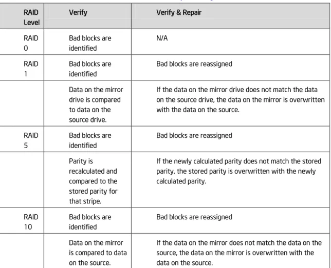
Verify and Repair
Intel® RSTe will provide support for Verify and Repair.
The RAID volume data verification process identifies any inconsistencies or bad data on a RAID 0, RAID 1, RAID 5, or RAID 10 volume.
The RAID volume data verification and repair process identifies and repairs any inconsistencies or bad data on a RAID 1, RAID 5, or RAID 10 volume.
The following describes what occurs for each RAID level:
Table 1. Verify and Repair RAID
Level
Verify Verify & Repair RAID
0
Bad blocks are identified
N/A RAID
1
Bad blocks are identified
Bad blocks are reassigned Data on the mirror
drive is compared to data on the source drive.
If the data on the mirror drive does not match the data on the source drive, the data on the mirror is overwritten with the data on the source.
RAID 5
Bad blocks are identified
Bad blocks are reassigned Parity is
recalculated and compared to the stored parity for that stripe.
If the newly calculated parity does not match the stored parity, the stored parity is overwritten with the newly calculated parity.
RAID 10
Bad blocks are identified
Bad blocks are reassigned Data on the mirror
is compared to data on the source.
If the data on the mirror does not match the data on the source, the data on the mirror is overwritten with the data on the source.
Check Pointing
Intel® RSTe will provide the ability to perform Check Pointing to be able to track forward progress on read patrol, array rebuilds and volume migration if interrupts occur. After resuming, the operation will restart from the last valid stage reached.
Intel® RSTe User’s Guide 19
Bad Block Management
Intel® RSTe will provide support for Bad Block Management.
In the course of rebuilding a degraded RAID volume, where one of the member disks has failed or been removed, and is being replaced by a ‘spare’ drive, the redundant contents of the other drive(s) are read and then used to reconstruct data to be written to the spare drive. In case a read failure occurs sometime during this rebuild process, the data to be written to the spare will not be available and therefore lost. In this scenario, rather than mark the entire RAID volume as failed, we can mark only those sectors on the spare that are known to have indeterminate data, in a log of such bad sectors. This bad block management log can be used to reflect error status whenever any attempts are made to access those sectors of the spare.
Dirty Stripe Journaling
Intel® RSTe will provide support for Dirty Stripe Journaling (DSJ). DSJ is used to help speed up RAID 5 write power loss recovery by storing the write stripes that were in progress at the time of the failure. The DSJ allows rapid recovery without having to rebuild the entire volume. The DSJ is only utilized when disk write cache is DISABLED.
Partial Parity Logging (PPL)
Intel® RSTe will provide support for Partial Parity Logging (PPL). PPL is used to record the results of XORing old data with old parity. PPL is currently saved as part of the RAID member information and is only utilized when writing RAID 5 parity. It helps protect against data loss when a power failure or a system crash occurs by allowing data to be rebuilt by utilizing the PPL information.
OS Installation
Intel® RSTe will provide the OS appropriate RSTe driver files required for installation during the OS setup onto a drive or RAID volume attached to either the AHCI or SCU controllers.
Selectable Boot Volume
Intel® RST 3.0 will support the ability to select any volume as the OS boot volume. The OS installer will be able to install the operating system onto RAID volume. There will be no need for RAID management (e.g. volume creation/deletion) support from within OS installer.
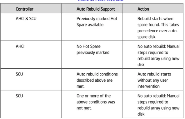
Auto Rebuild
Intel® RSTe will provide support for the ability to automatically rebuild a failed or degraded RAID volume. This feature will begin when a member disk of the array has failed and a suitable replacement disk with sufficient capacity is available. As soon as the failure occurs the rebuild process will begin automatically, using the marked Hot Spare disk, without user intervention. If a marked Hot Spare disk is not present, the automatic rebuild process will begin under the following conditions:
• Another free disk is plugged into the same directly attached physical location as the failed drive • The newly inserted disk size is at least as large as the amount of space used per disk in the current array
20 Intel® RSTe User’s Guide
• The newly inserted disk must be the same type (SAS/SATA) as the disk being replaced or the rebuild will not start.
• If the newly inserted disk contains Intel® RSTe (or Intel® RST) metadata with current status of member being offline or contains no Intel® RSTe (or Intel® RST) metadata.
• The newly inserted disk has not reported a SMART event.
The following table summarizes the functionality:
Table 2. Auto Rebuild
Controller Auto Rebuild Support Action AHCI & SCU Previously marked Hot
Spare available.
Rebuild starts when spare found. This takes precedence over auto-spare disk.
AHCI No Hot Spare
previously marked
No auto rebuild: Manual steps required to rebuild array using new disk
SCU Auto rebuild conditions described above are met.
Auto rebuild starts without any user intervention
SCU One or more of the
above conditions was not met.
No auto rebuild: Manual steps required to rebuild array using new disk
Automatic rebuild support will default to OFF for Intel® RSTe and can be enabled through the Intel® RSTe GUI.
Error Threshold Monitoring/Handling
Intel® RSTe will support the ability to initiate an automatic RAID rebuild to a marked hot spare drive in the event of a drive SMART event alert that indicates a failure. (Windows*Only)
Unified Extensible Firmware Interface (UEFI)
Intel® RSTe will support UEFI for the SCU and AHCI controllers using common metadata.
Disk Write Cache
Intel® RSTe will support the ability to enable/disable Disk Write Cache through the Intel® RSTe GUI. Disk Data Cache will be disabled by default.
RAID Volume Read Cache
Intel® RSTe will support the ability to enable/disable RAID Volume Read Cache through the Intel® RSTe GUI. RAID Volume Read Cache will be enabled by default.
Intel® RSTe User’s Guide 21
Write Back Cache
Intel® RSTe will support the ability to enable/disable Write Back Cache through the Intel® RSTe GUI. Write Back Cache will be disabled by default.
Volume Cache Increase
Intel® RSTe will increase the volume cache size to 16MB for SCU volumes and 16MB for AHCI volumes.
RAID Volume Size
Intel® RSTe will provide support for RAID volumes that are larger than 2 Terabytes.
RAID Boot Volume Size
Intel® RSTe will provide support for RAID Boot volumes that are larger than 2 Terabytes.
Disk Monitor Service
Intel® RSTe will support the ability to provide a disk monitoring service. The service will be active by default and executed as a system service. The service will monitor the system for SMART and RAID volume state changes events. The changes will be logged in the system log.
Failed Drive Reinsertion
Intel® RSTe will support the ability to recognize a failed drive re-inserted into the array. If able, Intel® RSTe will attempt to rebuild the volume to that drive. If not able, Intel® RSTe will mark the drive accordingly in the GUI.
Drives Supported
Intel® RSTe will provide support for current production SATA drives from “any” manufacturer on the AHCI controller. SAS and SATA drives supported on the SCU controller are outlined in Appendix C (Hardware Compatibility List). There will also be support for drives that are larger than 2 Terabytes as well as drives that support 4KB physical (512B logical) sectors.
Safe Mode Support
Intel® RSTe will provide support for booting into Safe Mode for all supported OSs.
Non-Intel Controller Support
Intel® RSTe will not hinder, break or prevent operation of non-Intel® Controllers (SATA, PATA, SATA or RAID).
Device Configuration
Intel® RSTe will support the ability, at initialization, to read the system registry to get configuration setting in order to set the appropriate operational parameters.
22 Intel® RSTe User’s Guide
Power Management
The Intel® RSTe product will support all the necessary power management functions required by the OSs.
Staggered Spin-up
Intel® RSTe will provide support for staggered spin-up on the SCU controller for those hard drives that support this feature.
Exporting SATA Drives on AHCI Controller
Intel® RSTe RAID Legacy Option ROMs will export those drives directly attached on a port order basis. This will be for both the AHCI controller.
ATAPI
Intel® RSTe will provide support for ATAPI devices. Intel® RSTe RAID Legacy Option ROM will only support HDD devices (not ATAPI).
Solid State Drives (SSD)
Intel® RSTe will support SSDs as if they are Hard Disk Drives.
AHCI Controller
Intel® RSTe will support TRIM on the AHCI controller in a non-RAID configurations.
SCU Controller
Intel® RSTe will support TRIM on the SCU controller in a non-RAID configurations.
Email Alerting and Notification
Note: This feature has a platform specific limitation. It is supported only on Intel® C600 series chipset based platforms; not supported on legacy platforms/chipsets.
Intel® RSTe will support email notification of certain storage events (see Appendix A for supported events). The Intel® RSTe UI will provide the interface for enabling/disabling and configuring the email notification feature. The default setting in the UI is ‘disabled’.
The email notification feature allows the user to configure the platform to send alert / notification emails for each storage subsystem event that gets reported by the Intel® RSTe monitor service.
Configuration
The Intel® RSTe user application will provide the interface to allow the user to configure the email alert notification feature via the ‘Preferences’ tab of the UI (user must be logged on with administrative privileges).
• User can enable/disable the email notification feature
• User can configure the level of storage system events to be sent via email notification (Storage system Information, Warning, and/or Error). Any combination of the three alert levels can be configured to trigger an email notification
Intel® RSTe User’s Guide 23
• User can configure the email settings:
SMTP host (required) - Port (required) - Return email address (required) - Recipient email addresses (one address required, up to 3 maximum)
• User can configure the Email alert / notifications to send test emails to all addresses specified
Email Message Format
• Message header:
Item1. Return email address: email address of the originating computer
Item2. Recipient email address: email address of computer receiving the email notification
Item3. Subject: system formatted subject content with product name, the storage system event level and the hostname of the originating computer
• Message body:
Item4. Log file text: contains the text of the event as it is displayed in the event log
Item5. System report: contains the system configuration information of the originating computer as seen in the Intel® RSTe GUI Preferences page.
• Optional text:
Item6. This section is blank unless the originating computer’s OS is in a language other than English. If the originating computer sends items 4 and 5 in non-English, the English translation of those two items will appear in this section (for test emails, only item 4 will be translated here)
Protocol Support
Email alert shall support SMTP host & SMTP port.
Error Conditions
See Appendix A for list of supported storage events and their notification mechanism: • In the event of an SMTP server failure, the system will immediately attempt 3 retries. If the retries are unsuccessful, the system will discard the message without further attempts. The unsuccessful attempt will be written to the NT Event log.
• In the event of an improperly formatted email address in the “To’ field, the alert will fail and the failure will be written to the NT Event log.
• In the event of an improperly formatted email address in the “From” field, the alert will fail and the failure written to the NT Event log.
• If the SMTP name entered during configuration is an invalid format, the alert will fail and the failure written to the NT Event log.
Utilities
Install/Uninstall Utility
Intel® RSTe will be available through the use of an install package. The install package will automatically install the proper RSTe driver and GUI that corresponds to the OS being installed on. There will also be a mechanism available to uninstall the driver and GUI.
24 Intel® RSTe User’s Guide
NOTE: Great care must be taken when trying to perform the uninstall process. Removal of the driver could result in a system crash that could require a complete reinstallation of the operating system.
Intel® RSTe User’s Guide 25
3 RAID OpROM Utility
This section provides an introduction to the Intel® RSTe OpROM Utility.
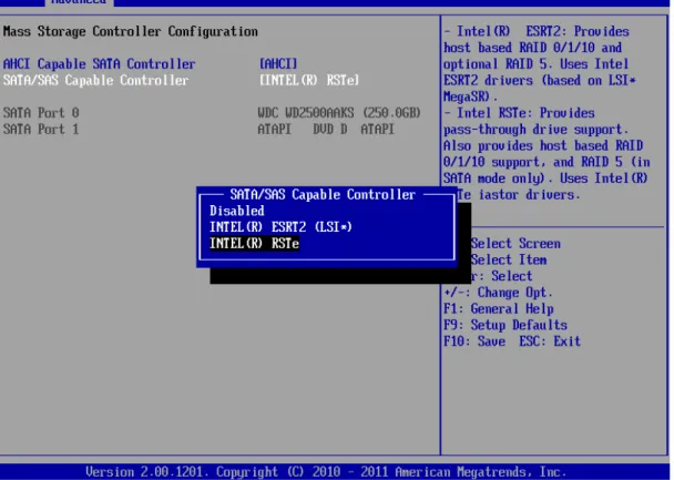
Enter Intel
®RSTe OpROM Utility
To use Intel® RSTe, firstly ensure that the Intel® Server Board has RSTe enabled in its BIOS SETUP. To enable it, press F2 during server board POST, so as to enter BIOS SETUP. Go to Advanced – Mass Storage Controller Configuration – SATA/SAS Capable Controller, and choose INTEL(R) RSTe.
Figure 1. Enable RSTe
Note: For Intel® Server Boards, it’s recommended to disable Quiet Boot in Main Tab in BIOS SETUP, so
as to automatically show Intel® RSTe scanning process during POST. If Quiet Boot is enabled, remember
to press ESC at the beginning of each reboot to show Intel® RSTe scanning process during POST.
During the POST, When seeing below screen indicating “Press <CTRL – I> to enter Configuration Utility”, press Ctrl – I to enter the Intel® RSTe Configuration Utility.
26 Intel® RSTe User’s Guide
Figure 2. Post Screen
Inside the Intel® RSTe Configuration Utility, use Up and Down arrow keys to select and option among 1. Create RAID Volume, 2. Delete RAID Volume, 3. Reset Disks to Non-RAID, 4. Recovery Volume Options, 5. Exit. Use ESC key to exit. Use Enter key to enter the selected menu.
Note: The functional keys on the keyboard are also indicated at the bottom of the screen. Always follow
Intel® RSTe User’s Guide 27
Figure 3. Intel® RSTe Configuration Utility
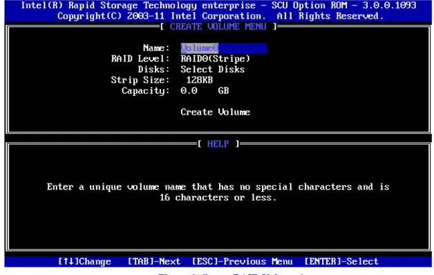
Create RAID Volume
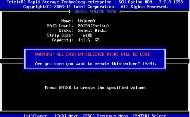
Choose 1. Create RAID Volume and press Enter key, to enter the Create Volume Menu. To create a RAID volume, you can use default name (Volume0) or type in a customized name of the volume. Follow the HELP text on the screen to get more detailed introduction of this function.
Figure 4. Create RAID Volume 1
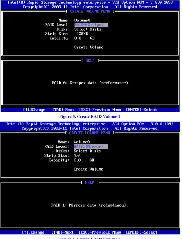
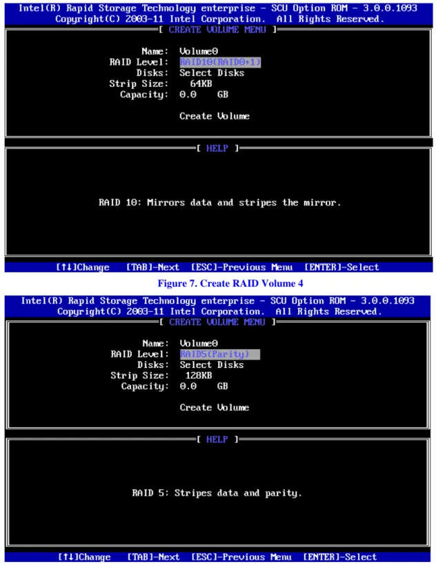
After inputting a volume name, press Tab key (or Enter key) to go to the next setting – RAID Level. Use Up and Down arrow keys to change the RAID Level among RAID0(Stripe), RAID1(Mirror), RAID10(RAID0+1), and RAID5(Parity). Refer to the HELP text to get more details.
Note: Recovery mode is to define one Master Disk to store data and one Recovery Disk to backup the
28 Intel® RSTe User’s Guide
Figure 5. Create RAID Volume 2
Intel® RSTe User’s Guide 29
Figure 7. Create RAID Volume 4
Figure 8. Create RAID Volume 5
30 Intel® RSTe User’s Guide
Figure 9. Create RAID Volume 6
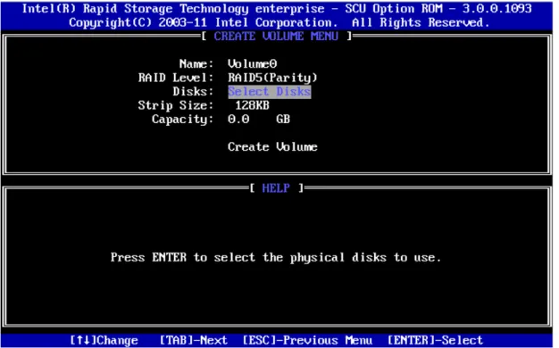
Press Enter key to enter the Select Disks Menu. Follow the hints at bottom of the pop-up menu to select disks. In this example, RAID Level is set as RAID5(Parity), so that 3 or more disks need to be selected. The selected disks will have a green mark on the left side of their Port numbers. After the choices, press Enter key and follow the text on screen to finish this step.
Figure 10. Create RAID Volume 7
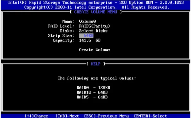
In the Strip Size option, use Up and Down arrow keys to select the wanted stripe size. If you don’t know which value to choose, follow the suggestion in the HELP text to set the value.
Intel® RSTe User’s Guide 31
Figure 11. Create RAID Volume 8
In the Capacity option, either accept the default value, which is the largest possible volume, or type in a number as the volume size.
Figure 12. Create RAID Volume 9
In the Create Volume Option, when confirmed, press Enter key to create the RAID volume. A warning message will pop up on screen. Confirm if previous data is no longer needed, and press Y to go on creating the new RAID volume, or press N to cancel the creation.
32 Intel® RSTe User’s Guide
Figure 13. Create RAID Volume 10
After the RAID volume is created, the Disk/Volume information is displayed in middle of the main menu, listing the key information such as ID number, Name, RAID level, strip size, volume size, status and whether this is a bootable volume.
Intel® RSTe User’s Guide 33
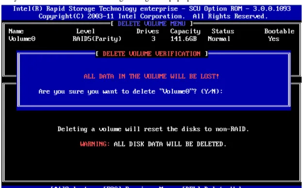
Delete RAID Volume
For any RAID volume that is no longer needed, choose 2. Delete RAID Volume and press Enter key to enter the Delete Volume Menu, in order to remove the volume from the Intel® RSTe.
Figure 15. Delete RAID Volume 1
Use Up and Down arrow keys to select the RAID volume that is no longer needed. Press DEL key to delete the volume. A warning message will pop up on screen.
34 Intel® RSTe User’s Guide
Double confirm if data on the volume can be deleted. Press Y to go on deleting the RAID volume, or press N to cancel the deletion.
Reset Disks to Non-RAID
This feature is used when specific disk needs to be set back to non-RAID mode. For example, in a RAID5 volume, if one disk is set to non-RAID mode, this disk can work in pass-through (non RAID) mode, or join in the configuration of another RAID volume. The RAID5 volume will be in degraded mode due to loss of this disk, and can be rebuilt if another disk joins this RAID5 volume. This feature is useful when specific drive needs to be replaced by another one. In the Main Menu, choose 3. Reset Disks to Non-RAID and press Enter key to enter the Reset Disk Data option.
Figure 17. Reset Disks to Non-RAID 1
Use Up and Down arrow keys to select the target disk, and press Space key to mark the disk with a green mark on left side of its Port number. Press Enter key to reset this disk. A question will pop up at lower side of the screen.
Intel® RSTe User’s Guide 35
Figure 18. Reset Disks to Non-RAID 2
When confirmed, press Y to go on resetting this disk to Non-RAID mode. After this, if system detects both a “Degrade” volume and disk available for rebuilding, a Degraded Volume Detected window will pop up, asking for selecting a disk to initiate a rebuild.
Figure 19. Reset Disks to Non-RAID 3
Choose an available disk and press Enter key to initiate the rebuild, or press ESC key to cancel a rebuild and leave the RAID volume in degrade status. Below screenshots show the RAID volume in rebuild status or in degraded status.
36 Intel® RSTe User’s Guide
Figure 20. Reset Disks to Non-RAID 4
Intel® RSTe User’s Guide 37
4 Operating Systems Installation and Driver Update
This section will focus on the operating system installation on the Intel® C600 series chipset based server boards, and driver update after the operating system is installed.
Installing Microsoft* Windows*
The following instructions will show how to install a Microsoft* Windows 2008 R2 onto a disk in Intel® RSTe non-RAID or RAID mode. For this example, the following is assumed:
- Intel® RSTe is enabled in the Intel® Server Board BIOS SETUP. - The optical disk drive is attached to the Intel® Server Board. 1. Select the desired language and select Next
38 Intel® RSTe User’s Guide
Intel® RSTe User’s Guide 39
40 Intel® RSTe User’s Guide
5. Select Custom (advanced)
6. At this point if Intel® RSTe RAID volume is created, the Intel® RSTe driver must be loaded to continue loading the operating system installation information. Insert the USB drive that contains the RSTe driver and select Load Dr iver ,then select Br owse
Intel® RSTe User’s Guide 41
7. Navigate to where the Intel® RSTe driver is located.
8. The correct driver should be highlighted. If not, please highlight the appropriate driver and select Next
42 Intel® RSTe User’s Guide
Intel® RSTe User’s Guide 43
Manual Installation of the Intel
®RSTe driver in OS
To install the Intel® RSTe driver manually, select Device Manager in the OS. Below is one of the ways to access Device Manager:
44 Intel® RSTe User’s Guide
2. In windows, click Star t and then slect Contr ol Panel
Intel® RSTe User’s Guide 45
Select System
46 Intel® RSTe User’s Guide
Step 5:
Intel® RSTe User’s Guide 47
48 Intel® RSTe User’s Guide
Step 8: Select Br owse to navigate where the driver resides
Step 9: Navigate to where the driver is located and select the INF file from the driver folder with that has the same OS version as the system.
Intel® RSTe User’s Guide 49
Step 11:
Intel® RSTe User’s Guide 51
5 Graphic User Interface Utility in Operating
Systems
This section will focus on Intel® RSTe Graphic User Interface (GUI) Utility installation. To install the Intel® RSTe GUI Utility, the Microsoft* .NET 3.5 or above must be installed and enabled.
Example of .NET 3.5 enabling in Windows 2008 R2*
Microsoft* Window 2008 R2* default installation already includes the installation of .NET 3.5. The following steps show an example of how to enable it.
Choose Server Manager:
52 Intel® RSTe User’s Guide
In the screen below, expand .NET Fr amwor k 3.5.1 Featur es and check the . NET Fr amewor k 3.5.1 Featur es.
Intel® RSTe User’s Guide 53
54 Intel® RSTe User’s Guide
Click Next
Intel® RSTe User’s Guide 55
Wait for the installation to go on
56 Intel® RSTe User’s Guide
Intel
®RSTe GUI Utility Installation
After .NET 3.5 or above is installed and enabled under Microsoft* Windows*, go to the GUI folder of the Intel® RSTe software package downloaded fr
installation file is a *.EXE file, with the name similar as iata_cd.exe, or else. Run this *.EXE file and follow the steps on screen to finish the installation.
The Intel® RSTe GUI Utility enables the creation and deletion of RAID volumes, as well as other configuration and management features that the legacy OpROM doesn’t support.
Open Intel
®RSTe GUI Utility
There are 2 ways to launch the Intel® RSTe GUI. In both cases the UI needs to be launched with Admin privileges so please right click on the icon and select “Run as Administrator”.
1) Launch via the desktop Icon.
Intel® RSTe User’s Guide 57
3) Click on Yes to continue
Volume Creation
The following are some example of some RAID Volume Creations. In the examples the system has been configured to support Intel® RSTe. There are two SATA drives attached to the AHCI
58 Intel® RSTe User’s Guide
C600 chipset based controller, and an expander connected to the last four ports of the Intel® C600 chipset based controller.
Create 2 Drive RAID 1 Boot Volume
The following example will step through the process of turning a single Boot disk into a 2 drive RAID 1 boot volume
1. Select Cr eate to begin the process
2. Select the Intel® C600 ser ies chipset SATA RAID Contr oller , then select Real-time data pr otection (RAID1). Finally select Next to continue.
Intel® RSTe User’s Guide 59
3. To configure the volume, you can first specify the Name of the volume. In this example it has been named RAID1_BootVolume. Next select the two drives to be included in the volume. Notice that for Do you want to keep data fr om one of the selected disks question, Yes has already been selected. Under the Advanced tab you can choose to Enable volume wr ite-back cache. Once all of the desired options have been selected, click Next to continue.
60 Intel® RSTe User’s Guide
4. Under Confir m Volume Cr eation select Pr oceed with deleting data then click on Cr eate Volume.
Intel® RSTe User’s Guide 61
62 Intel® RSTe User’s Guide
6. Under the Volumes section the new Array and RAID Volume are displayed. By selecting the RAID volume (RAID1_BootVolume), the Volume Properties (to the right) will appear with the current status and properties of the newly created RAID volume. The Boot Disk has successfully been migrated to a 2 drive RAID1 Boot Volume. The system will now be able to boot from this volume.
Intel® RSTe User’s Guide 63
Create a 2 Drive RAID 0 Volume
In this example the two SATA drives that are directly connected to the Intel® C600 chipset will be made into a two drive RAID 0.
64 Intel® RSTe User’s Guide
2. Select Intel® C600 ser ies chipset SAS RAID Contr oller , then select the Optimized disk per for mance (RAID 0) option and then click Next to continue.
Intel® RSTe User’s Guide 65
3. To configure the volume, you can first specify the Name of the volume. In this example it has been named RAID0_DataVolume. Next select the two drives to be included in the volume. Notice that for Do you want to keep data fr om one of the selected disks question, No has already been selected. The Yes option may be selected if desired. Under the Volume Size, the option to specify the size of the RAID volume is available. Under the Advanced tab you can specify the Data str ipe size and/or choose to Enable volume wr ite-back cache. Once all of the desired options have been selected, click Next to continue.
4. Under Confir m Volume Cr eation, select Pr oceed with deleting data (if the option appears) otherwise, click Cr eate Volume to continue the process.
66 Intel® RSTe User’s Guide
Intel® RSTe User’s Guide 67
6. Under the Volumes section, the new Array and RAID Volume (RAID0_DataVolume) will appear. By selecting the RAID Volume, the Volume Properties section (to the right) will show the properly information of the newly created RAID volume
Create a 5 Drive RAID 5 Volume
In this example some of the disk drives that are in the attached enclosure will be used to create a 5 drive RAID 5 volume.
68 Intel® RSTe User’s Guide
2. Select the Intel® C600 ser ies chipset SAS RAID Contr oller and then select Efficient data hosting and pr otection (RAID 5) followed by Next to continue
Intel® RSTe User’s Guide 69
3. To configure the volume, you can first specify the Name of the volume. In this example, the default name is used Volume_0000. Next select the two drives to be included in the volume. Notice that for Do you want to keep data fr om one of the selected disks question, Yes has already been selected. Under the Advanced tab you can choose the Data str ipe size, Enable volume wr ite-back cache or Initialize volume. For a 5 drive RAID 5, the initialization will begin automatically. This is done to improve the operational performance of the RAID 5 volume. For RAID 5 volumes under 5 disks, the initialization process will not begin automatically. Once all of the desired options have been selected, click Next to continue.
4. Under Confir m Volume Cr eation, select Pr oceed with deleting data (if the option appears) otherwise, click Cr eate Volume to continue the process.
70 Intel® RSTe User’s Guide
Intel® RSTe User’s Guide 71
6. Under the Volumes section, the new Array and RAID Volume (RAID0_DataVolume) will appear. By selecting the RAID Volume, the Volume Properties section (to the right) will show the properly information of the newly created RAID volume.
GUI Utility Overview
This section will go over the different part of the UI along with the information that can be obtained and actions that can be taken.
Devices
Under the Devices portion of the UI (to the left) there are the two controllers; the Intel® C600 series chipset SATA RAID Controller (when the AHCI Controller is set to RAID Mode) and the Intel® C600 series chipset SAS RAID Controller. By selecting a controller, the Co ntr oller Pr o per ties will appear to the right.
72 Intel® RSTe User’s Guide
Intel® RSTe User’s Guide 73
If the system has an enclosure and that happens to be selected, the Enclosur e Pr oper ties will appear to the right.
Viewing the RAID Volumes in Device Manager
Attached are some screen captures that show what Window* device manage may display after the RAID volume has been created.
1. Bring up Computer Management and select Windows* Device Manager . The newly created RAID volume should be shown under Disk dr ives
74 Intel® RSTe User’s Guide
2. Under Stor age -> Disk Management, the newly created RAID volume is now available to format.
Intel® RSTe User’s Guide 75
Volume Deletion
The following steps through the RAID Volume deletion process.
1. Select (left mouse click) the RAID Volume to be deleted in the middle under Volumes. Then on the right side under Volume Pr o per ties select Delete Volume.
Intel® RSTe User’s Guide 77
6 Intel
®
RSTe Command Line Interface (RSTCLI)
Utility Overview
RSTCLI is an end user command line utility used to do basic RAID operations on Intel® RSTe enabled systems. Intel® RSTe supports RAID0, RAID1, RAID5 and RAID10 volumes. RSTCLI supports creating RAID volumes through the create mode and managing RAID volumes through the Manage mode. In addition there are miscellaneous options such as help, status and version.
Options for Intel® RSTe are case sensitive. Both long and short versions of the options are given:
Table 3. Intel® RSTe Command Line Interface Utility Options
Flag Name Descr iption
-C --create Creates a volume and array if one does not already exist,
creates a new volume on an existing array; used to denote Create Mode
-I
--information
Displays controller, array, volume, enclosure and disk information; used to denote Information Mode
-M --manage Manages specific components of arrays, volumes and disks;
used to denote Manage Mode
-m --modify Modifies a volume or an array; used to denote Modify Mode
-h --help Prints documentation of how to invoke the program
-r --rescan Forces the system to rescan for hardware changes.
-V --version Prints version information
-q --quiet Suppress output for create, modify and manage. This will limit
output to error return codes only. This mode is used to facilitate the use of command line scripts.
General Usage
The general command line format of the RSTCLI is as follows:
r stcli [optional mode] <r aid-device> [option]{[options]}<component-device>
Note: rstcli.exe is for 32-bit Windows* operating systems and rstcli64.exe is for 64-bit. For the purposes of this section, rstcli will be used.
To see all available commands and options enter the following: r stcli –help
To obtain additional information on a particular optional mode enter the following command: r stcli [mode] –help
78 Intel® RSTe User’s Guide
Create
The create option is used to create RAID volumes. To create a RAID volume, enter the following: r stcli --cr eate --level x [--size y] [--str ip-size z] --name str ing [--cr eate-fr om-existing diskId] diskId {[diskId]}
Table 4. Create Options
Flag Name
-C --create
Creates a volume and array if one does not already exist. Creates a new volume on an existing array; used to denote Create Mode.
-E <<host>-<bus>-<target>-<lun>>
--create-from-existing <<host>-<bus>-<target>-<lun>>
If data is to be migrated from one of the disks, specify the disk with this flag. Disk identifier is SCSI address.
-l --level
-n <Volume name> --name <Volume name>
-s --strip-size
-z <size in GB> --size <size in GB>
Size in gigabytes. This is an optional switch. If switch is not used or size is specified to 0, then the maximum size available will be used.
Create Examples:
-C -l 1 -n Volume 0-1-0-0 0-2-0-0
--cr eate -l 0 -z 5 --name RAID0Volume 0-3-0-0 0-4-0-0 0-5-0-0 -C - 1 -E 0-1-0-0 -n VolumeWithData 0-2-0-0
--cr eate –help
Information
The Information option will provide information on arrays, controllers, disks, enclosures and volumes. To obtain the desired information, enter the following:
r stcli --infor mation --contr oller |--ar r ay|--disk|--enclosur e|--volume {[device]}
Table 5. Information Options Flag Name
-I --information
Displays controller, array, volume, enclosure, and disk information; used to denote Information Mode.
-a --array
Lists information about the arrays on the system. -c --controller
Lists information about the controllers on the system. -d --disk
Lists information about the disks in the system. -e --enclosure
Lists information about the enclosures on the system. -v --volume