DDM Distributed Database
Manager
for SQL and ODBC
Installation and User Guide
Version 5.27.xx
Communication Devices Inc. 85 Fulton St.
Boonton, NJ 07005 USA
Phone: 800 359 8561 Fax: 973 334 0545
Internet: [email protected] Last Revision 4/2010
Table of Contents
1 INTRODUCTION ... 1-1
1.1 DDMVERSIONS... 1-1
1.2 WHAT THIS MANUAL CONTAINS... 1-1
1.3 SYSTEM REQUIREMENTS... 1-1
1.4 README FILES... 1-2
1.5 CONTACT INFORMATION... 1-2
2 OVERVIEW ... 2-1
2.1 CDI’S ROLE IN NETWORK SECURITY... 2-1
2.2 DEVICE MANAGEMENT... 2-2
2.3 DATABASE ORGANIZATION... 2-2
3 INSTALLING THE DDM SQL VERSION ... 3-1
3.1 INSTALL THE DDMSQL SOFTWARE. ... 3-1
3.2 CREATE,INSTALL, OR UPGRADE THE DDMDATABASE ON THE SQLSERVER... 3-4
3.2.1 Create New SQL Server DDM Database ... 3-4 3.2.2 Create New Server DDM Database and import DDM Database Data... 3-5 3.2.3 Create/Upgrade SQL Server and Import DDM Databases ... 3-5 3.2.4 Upgrade Existing SQL Server DDM Database... 3-5
3.2.5 Upgrade DDM Client Only ... 3-6
3.4 EXECUTING THE DDMSQLPROGRAM:... 3-7
3.5 ACCESSING THE PROGRAM... 3-7
4 INSTALLING THE DDM ODBC VERSION... 4-1
4.1 INSTALLATION STEPS FOR DDMODBCVERSION... 4-1
4.2 ACCESSING THE PROGRAM... 4-3
5 GETTING STARTED... 5-1
5.1 STARTING THE DDMPROGRAM... 5-1
5.2 NAVIGATING THE DDM SOFTWARE... 5-1
5.3 OPENING SCREEN... 5-2
5.3.1 Device View ... 5-2
5.4 INSTALLATION AND SET UP OVERVIEW... 5-4
6 WORKING WITH GROUPS ... 6-1
6.1 ADD A GROUP... 6-1
6.2 RENAME A GROUP... 6-3
6.3 DELETE A GROUP... 6-3
6.4 GROUP MODIFICATIONS... 6-3
6.5 UNIGUARD GROUP MODIFICATIONS... 6-4
6.6 PORT AUTHORITY GROUP MODIFICATIONS... 6-6
6.7 MULTIGUARD GROUP MODIFICATIONS... 6-8
6.9 ENABLING THE REAL TIME LOG LIST... 6-10 6.9.1 Printing, Saving and Deleting the DDM Real Time Log ... 6-11 6.9.2 Deleting items from the DDM Real Time Log... 6-12
7 DEVICES ... 7-1
7.1 ADD A DEVICE TO A GROUP... 7-1
7.1.1 Duplicate a Device... 7-1
7.1.2 Move a Device ... 7-1
7.1.3 Use the Device Wizard to add a device ... 7-1
7.1.4 Modifying Device Properties... 7-3
7.1.5 Renaming a Device ... 7-3 7.1.6 Deleting a Device ... 7-3
7.2 CONFIGURING A DEVICE... 7-3
7.2.1 Device Info Screen ... 7-4
7.2.2 Country Dialing Using the DDM... 7-7
7.3 SETTING THE NETWORK PROPERTIES OF A SPECIFIC DEVICE... 7-8
7.3.1 Network Properties, IP Configuration ... 7-8
7.3.2 DDM Heartbeat Attributes ... 7-10
7.3.3 DNS Attributes ... 7-11
7.3.4 SNMP Attributes ... 7-11
7.3.5 Network Properties (versions below 4.01)... 7-11
7.3.6 Network Properties (IP type set for external) ... 7-12
7.4 SYSTEM OPTIONS... 7-12
7.4.1 Port Authority SAM Host Devices... 7-13
7.4.2 SAM Authentication Process ... 7-14
7.4.3 Port Authority devices... 7-14
7.4.4 UniGuard devices ... 7-14 7.4.5 UniGuard Clients ... 7-15
7.5 COMMUNICATIONS SCREEN... 7-16
7.6 DEFINED PORTS SCREEN... 7-16
7.6.1 Port Properties - Host Port Configuration... 7-18 7.6.2 Power Port Configuration ... 7-18 7.6.3 Slave Device Setting (For Port Authority Only) ... 7-18 7.6.4 Programmable ESC Code ... 7-18
7.7 REMOTE ENCRYPTORS SCREEN... 7-19
8 CLIENT ENCRYPTORS... 8-1
8.1 PORT AUTHORITY SAMCLIENT... 8-1
8.1.1 Device Info Screen for a Port Authority SAM Client Device,... 8-2 8.1.2 System Options for Port Authority SAM Client Encryptor ... 8-4 8.1.3 Communications Screen for Port Authority SAM Client Device ... 8-6
8.2 UNIGUARD CLIENT ENCRYPTOR... 8-7
8.2.1 AES/TDES Mode for UniGuard Client... 8-7
8.2.2 Client Encryptor pre-dialog ... 8-7
8.3 UNIGUARD CLIENT... 8-8
8.3.1 Adding a UniGuard Client... 8-8 8.3.2 UniGuard Client Device Information Screen ... 8-8 8.3.3 Network Properties for a UniGuard Client ... 8-10
8.3.4 UniGuard Client, System Options... 8-11
8.3.5 Communications Screen UniGuard Client... 8-12
8.4 SSECLIENT... 8-13
9 USERS ... 9-1
9.1 ADD A USER... 9-1
9.1.1 User Info ... 9-2
9.1.2 User Security... 9-3
9.1.3 Token Key Info Screen... 9-4
9.1.4 RSA SecurID Token Info ... 9-5
9.1.5 Encryption User and ENCRYPTOR ... 9-6
9.2 ADDING EXISTING USERS TO A GROUP... 9-7
9.3 DELETE A USER FROM A GROUP... 9-7
9.4 LISTING USERS OF A GROUP... 9-7
9.5 MODIFY PROPERTIES OF A USER... 9-8
9.6 USER LOCK LIST... 9-8
9.7 USER MANAGEMENT LIST... 9-8
10 SETTINGS... 10-1
10.1 SETUP SCREEN... 10-1
10.1.1 Modem Properties ... 10-3
10.1.2 Setup Properties for UniGuard... 10-3
10.2 DATABASE UTILITIES... 10-3
10.3 DBADMINISTRATOR LIST... 10-4
10.3.1 Enabling Automatic Services and Database Management... 10-4
10.3.2 Unlock Database Records... 10-5
10.3.3 DDM Seat Licenses DDM SQL only ... 10-5 10.3.4 Add Seat Licenses to Database DDM SQL only... 10-5
10.4 DEVICE LICENSE... 10-6
10.4.1 Adding Device Licenses to the database ... 10-6
10.5 RSASECURIDTOKEN ATTRIBUTES... 10-6
10.5.1 RSA Pin Length... 10-7
10.5.2 RSA Next Pin Mode ... 10-7
10.6 RSASECURIDENABLE FILES... 10-7
10.6.1 Add RSA SecurID Enable Files... 10-8
10.7 DDMLOG FILES PURGING SETUP... 10-8
10.8 DEFINE SNMPEVENTS... 10-9
10.9 SETTING UP MULTIPLE DDMPOLLING... 10-10
10.9.1 MultiPoll\License File Path DDM SQL only ... 10-10
10.9.2 DDM Polling Stations ... 10-10
10.9.3 Adding Poll Stations ... 10-10
10.9.4SELECT GROUPS TO POLL... 10-11
10.9.5 Edit a Station ... 10-11
10.9.6 Deleting a Station ... 10-11
10.10 DDMIPDIALOUT LIST... 10-11
10.10.1 Adding a non-CDI device ... 10-12 10.10.2 Edit a non-CDI Device... 10-13 10.10.3 Delete Device ... 10-13
10.10.4 Adding CDI Devices to the IP Dialout ... 10-14
10.11 EMAIL ALARM ALERT LIST... 10-14
10.11.1 Enabling the Email Alerts feature... 10-15
10.11.2 Email User Properties ... 10-16
10.11.3 Adding an Email User ... 10-16
10.13 SSMSETTING... 10-18
10.14 DDMRADIUS SERVICE... 10-18
10.15 EXPORT DDMDATABASE TO XMLFILE... 10-18
11 PROGRAMMING DEVICES ... 11-1
11.1 PROGRAM MENU... 11-1
11.2 PROGRAMMING DEVICES OVERVIEW... 11-3
11.2.1 Program-Update Device... 11-3 11.2.2 Program-Reload Device ... 11-4 11.2.3 Program Group... 11-4
11.3 RESET A GROUP... 11-4
11.4 PROGRAMMING FLASH FOR A SELECTED GROUP... 11-5
11.5 PROGRAMMING FLASH FOR A SELECTED DEVICE... 11-5
11.6 PROGRAM ALL DEVICES... 11-5
11.7 TELNET TO DEVICE... 11-6
11.8 STATUS... 11-6
11.9 PROGRAM DEVICE CONTACT LIST... 11-6
11.10 CONFIGURE THE IPCARD OF A DEVICE... 11-7
11.11 DDMPROGRAMMING A REMOTE SSE USING MODEM COMMUNICATIONS... 11-7
11.12 DDMFLASH PROGRAMMING A REMOTE SSE USING MODEM COMMUNICATIONS... 11-8
11.13 DISPLAYING THE DDMREAL TIME INFORMATION FOR A SELECTED DEVICE... 11-8
11.14 DISPLAYING THE AUDIT INFORMATION FOR A DEVICE... 11-9
11.15 PROGRAM GROUP FLASH DEVICES IPCARD... 11-10
11.16 CLEAR DEVICE... 11-11
12 REPORTING AND MAINTENANCE ... 12-1
12.1 REPORT VIEW... 12-1
12.2 REPORT TEMPLATES... 12-2
12.3 AUDIT TRAIL MAINTENANCE... 12-3
12.3.1 Purging the Audit Trail... 12-4
12.3.2 Archive DDM ODBC Databases ... 12-4
12.3.3 .Purging the Audit Trail... 12-4
12.3.4 Purging the DDM Real Time Log ... 12-5
12.4 EXIT THE REPORT SECTION AND RETURN TO THE DEVICES/USER VIEW... 12-6
13 DDM POLLING SERVICES ... 13-1
13.1 ABOUT POLLING SERVICES... 13-1
13.2 EDITING A POLLING SERVICE... 13-2
13.3 ACCOUNT TYPES... 13-3
13.4 POLLING MODES... 13-5
13.4.1 Poll all devices in the database... 13-5
13.4.2 Poll by selected groups. ... 13-5
13.4.3 Poll by selected devices... 13-6
13.5 INSTALLING A POLLING SERVICE... 13-7
13.5.1 Scheduling a Service ... 13-8
13.5.2 Stopping or Deleting a Polling Service... 13-10
Appendix A Cabling
Appendix B Multiport Options Appendix C Audit Trail Events
1 INTRODUCTION
The Distributed Database Manager (DDM) software products are designed to remotely manage the databases of CDI’s UniGuard, Port Authority, Port Authority SAM, and SSE devices.
The software products are menu-driven and easily learned. The program is designed to function using the Windows XP, operating system. Windows Server 2003 and MS/SQL 2005 are recommended for DDM SQL server installations.
1.1 DDM Versions
Two versions of the DDM are available: DDM SQL and DDM ODBC.
The DDM SQL version is designed to handle multiple concurrent sessions. Through the SQL Server database, a number of DDM managers can access the database simultaneously. The DDM databases are stored on the SQL Server database and are easily modified, synchronized, and updated. All information can be backed up for easy and safe restoration in the event of system failure using the SQL Server database utilities.
The DDM ODBC version cannot handle multiple concurrent sessions and is meant for a single DDM connection on the concurrent machine. The DDM ODBC databases are stored on a Microsoft Access database. All information can be backed up for easy and safe restoration through the DDM ODBC Utilities.
1.2 What this Manual Contains
This manual will provides installation and operation instructions for both the SQL and the ODBC versions of the DDM program.
Installation and operation instructions for the Port Authority, Port Authority SAM, and SSE devices are detailed in their respective manuals.
1.3 System Requirements
The DDM software requires a workstation (PC) that meets the following requirements.
Memory: 1GB RAM minimum
Operating System: Windows XP, Windows 2003 server Hard Drive: 100 GB minimum
CD or DVD drive
The program is loaded from a CD ROM Disk. A separate mini-CD disk, “The Device License” disk, is provided which will enable the number of devices (UniGuard, Port Authority and or SAM Units) allowed stored in the system. The number of devices that can be managed is virtually infinite, limited only by the storage capacity of the workstation.
1.4 Readme Files
The program disk contains a readme file that contains the updates and related information. Please read this file before installing the software.
1.5 Contact Information
If you need to contact us, please call Communication Devices Inc. at 1-800-359-8561 or visit us at www.commdevices.com.
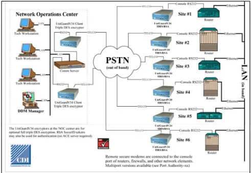
2 OVERVIEW
A network is comprised of routers, firewalls, and other network elements. These elements are usually monitored by Network Operations Center (NOC) technicians. When there is a problem, the technicians must access the console port of the router or other network element to reset the device or perform other maintenance. The console port can be accessed by in-band or out-of-band communications.
For security purposes, it is important to limit access to this port to authorized users, and protect the information being sent from the technician to the router or other element.
2.1 CDI’s Role in Network Security
CDI offers devices that provide both authentication and encryption functions or authentication only. These devices provide secure out-of-band communication between the technicians and network elements. Out-of-band communication uses a secondary path for communication providing more security and enabling devices to be contacted even when there is a network problem
Before accessing a router, a technician connects to a CDI UniGuard or Port Authority device and authenticates. Each CDI device maintains a database of authorized users and authentication information. Once the user has successfully authenticated, he/she is permitted to access the network element. All information is encrypted. On the NOC side, a UniGuard device can be set to encryption mode only and encrypt the information being sent by the technician.
In certain situations, the encryption of data is not required. For these situations, a secure authentication modem (SAM), which operates out-of-band and provides authentication only, can be installed.
2.2 Device Management
The CDI devices are managed remotely by the CDI’s Distributed Database Manager (DDM) application running on a Windows PC. The number of devices managed by the DDM is limited by the resources of the PC.
The DDM provides centralized management and maintains a central database of users and devices enabling devices and users to be added, deleted, or modified from one location.
Each UniGuard and Port Authority device has a local database updated from the DDM database. The DDM communicates with remote devices over dial-up phone lines, serial ports, or IP connections. All communications are encrypted.
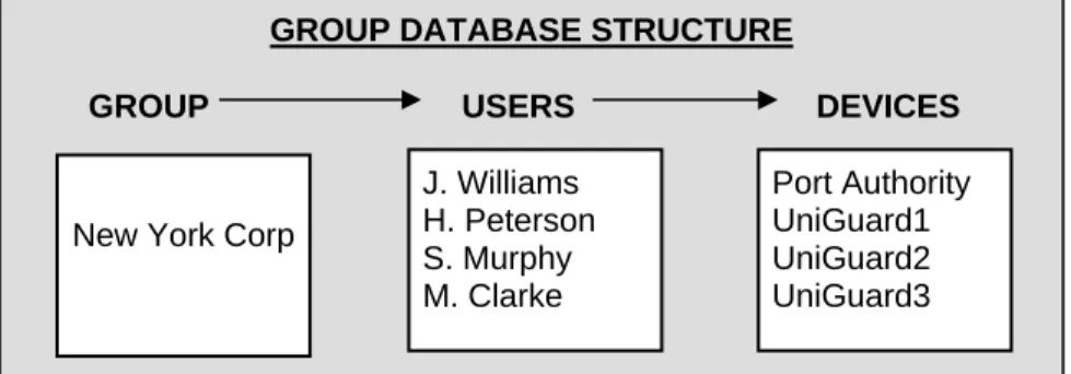
2.3 Database organization
The central database maintained by the DDM is separated into groups. A group is a collection of devices that share a common user database. A group can be defined by region, company, or by some other association. A device can only belong to one group but an individual user can be assigned to multiple groups.
When changes are made to the database, the changes can be sent to one device, devices of one group, or all devices. A log file is maintained by the DDM for tracking system events, such as database updates.
In this example, the Group New York Corp has four users, each having access to any of four devices. If a device is a multiport device, such as the Port Authority, a user may have access to a single port, several ports, or all ports of the Port Authority. The number of devices assigned to a group as well as the total number of groups is virtually infinite, limited only by the storage capacity of the computer running the DDM program.
GROUP DATABASE STRUCTURE
GROUP USERS DEVICES
New York Corp
J. Williams H. Peterson S. Murphy M. Clarke Port Authority UniGuard1 UniGuard2 UniGuard3
3 INSTALLING THE DDM SQL VERSION
This section provides the DDM Administrator with DDM Installation instructions for the SQL version. The SQL version should be installed if multiple concurrent sessions are necessary.
To install the DDM SQL version, you must install the software and then create, upgrade, or install DDM database.
.
3.1 Install the DDM SQL software.
Place the installation CD-ROM in your CD drive. After a few seconds, the Installation Guide screen is displayed. To install the DDM software, click on the “Install CDI Distribution Database Manager Software” link.
The InstallShield Wizard, which guides you through the installation, is installed.
The InstallShield Wizard starts the installation of the DDM-SQL software.
Click Next to continue with the
The Software License Agreement is displayed. After you have read it, click the appropriate radio button to accept
the agreement. Click Next to continue
with the installation
The Customer Information screen is displayed. Enter your User name and Organization and select an installation option.
The first option allows anyone who has access to this computer to use this program. The second one limits access to the user whose name appears in the User Name window.
Click Next to continue the installation.
During this part of the installation you will need to choose the folder in which the DDM Software is to be installed. To
use the suggested folder, click Next to
continue or click Change to select a
After all the required information has been entered, the DDM Install Shield Wizard displays a summary page of the information entered. To change the
information, click Edit. If no changes
are required, click Install to start the
installation process.
A completion message is displayed when the software has been successfully
installed. Click Finish to close the
InstallShield Wizard.
After you click Finish, the DDM Registration
Form is displayed. To be eligible for covered upgrades and support, this form must be returned to CDI. You may submit the form by email or print it and send it to the address listed on the form.
CDI needs this information to contact you, or the current administrator with important updates that may affect the performance of the products. This is not used as a sales tool
3.2 Create, Install, or Upgrade the DDM Database on the SQL Server.
After the DDM program has been installed, you must then create, load, or upgrade the databases on the SQL server. Click on the appropriate option. Each option is explained below.
3.2.1 Create New SQL Server DDM Database
Select the "Create New SQL Server DDM Databases from the DDM Database” if you are installing the database for the first time. This means that the DDM database does not exist on the SQL Server and old DDM databases (access databases) do not need to be imported onto the SQL Server.
You will be asked to confirm that you have the appropriate rights to create a new SQL database before you can continue.
If the database already exists, a message indicating this is displayed. You must logon on to the SQL Server and have administration rights. You will be asked to confirm that you have the
appropriate rights to create a new or modify the SQL database before you can continue.
3.2.2 Create New Server DDM Database and import DDM Database Data
Select the "Create New SQL Server DDM Databases and Import Access DDM Database Data to the new SQL Server DDM Database” only if the DDM Database does not exist on the SQL Server and you need to import old DDM Databases (access databases) onto the SQL Server.
Before you start, make sure all users are disconnected from the DDM databases. Copy the databases ddmdata.mdb and ddmlog.mdb databases to another directory as a backup.
The DDM installation will create the DDM databases in the SQL Server, then copy the database information from the old DDM databases to the new SQL Server DDM databases.
TIP
It may take as long as 15 minutes to import large DDM databases. To avoid interference from the network during this time, copy the databases to your local PC and perform the upgrade there. Point the “ddmdata” and “ddmlog” databases to this directory on your PC from the ODBC Administrator dialog in the Windows Control Panel and then continue with the upgrade.
3.2.3 Create/Upgrade SQL Server and Import DDM Databases
To Create/Upgrade an SQL Server and Import Multiple Access DDM Databases into the SQL Server, click on the button labeled Create/Upgrade an SQL Server and Import Multiple Access DDM Databases into the SQL Server.
3.2.4 Upgrade Existing SQL Server DDM Database
Select the " Upgrade Existing Server DDM Database” option from the DDM Database Upgrade Program screen. For this to occur the DDM databases must already exist in the SQL Server.
You will need to logon to the SQL Server and have administration rights to be able to create and alter databases. The DDM installation will upgrade the DDM databases in the SQL Server.
Enter a Username and Password that has full rights in the SQL Server.
3.2.5 Upgrade DDM Client Only
Select the button labeled "Upgrade DDM Client Only" from the DDM Database Upgrade Program screen. This will only install or upgrade the DDM Client files, bypassing a SQL Server DDM database creation or upgrade process.
For RSA SecurID Token type users that are RSA SecurID Token type, RSA SecurID will supply a disk with their serial numbers.
3.3 Version Control
At the end of the installation, the user is given the option of implementing DDM Version Control. When version control is implemented, DDM stations can be updated to the latest production DDM software when the DDM program is started. If the DDM version is below 5.27.01, a query will be presented to the DDM user to update its files to the latest DDM production files. The DDM Database level in the SQL Server must be at or above version 5.26 for this to be presented to the DDM user.
If Version Control is not implemented during the installation, the install files would have to be run again in order to get to the option of implementing Version Control.
If the user accepts this installation query, the installation will create a directory
(…\\DDMInstalls\DDM52701\...) in the shared path (License File Path) with all the DDM installation files for version 5.27.01. The DDM/SSM users must have full rights to this shared path. If this path is not defined, DDM Version Control cannot be implemented.
3.4 Executing the DDM SQL Program:
Once the CDI Distributed Database Manager SQL has been successfully installed, remove the Distributed Database Manager CD ROM disk from the CD ROM. To run the CDI Database Manager application, click the Start button and then select CDI DDM Manager SQL from the program list. You may also start the application from the Finished Installation window.
3.5 Accessing the Program
To access the program, the DDM user must successfully authenticate by using one of two types of SQL Server authentication: Trusted Connection or SQL Server User Name/Password.
Trusted Connection
A Trusted Connection uses Windows authentication credentials. Enter the user name and password that you use to logon to your PC workstation.
SQL Server User Name/Password
The SQL Server authentication relies on the SQL server security options set up by the System Administrator. You must enter the SQL Server name to successfully logon to the DDM SQL Server.
Connection Timeout: Enter the number of seconds the system will wait to connect to the SQL Server (default value is 15 seconds).
4 INSTALLING THE DDM ODBC VERSION
This section provides the DDM Administrator with DDM instructions for the
installation of the DDM Installation—ODBC version. The ODBC version is selected when capability of multiple concurrent sessions is not necessary and there are a limited number of users.
4.1 Installation Steps for DDM ODBC Version
Place the installation CDROM in your CD drive. After a few seconds, the Installation Guide screen is displayed. To install the DDM software, click on the “Install CDI Distribution Database Manager Software” link.
The InstallShield Wizard guides you through the installation of the DDM-ODBC software. Click Next to continue with the installation.
The Software License Agreement is displayed. After you have read it, click the appropriate radio button to accept the agreement. Click Next to continue with the installation
The Customer Information screen is displayed. Enter your User name and Organization and select an installation option.
The first option allows anyone who has access to this computer to use this program. The second one limits access to the user whose name appears in the User Name window.
Click Next to continue the installation.
During this part of the installation you will need to choose the folder in which the DDM Software is to be installed. Click Next to use the suggested folder or click Change to select a different location.
After all the required information has been entered, the DDM Install Shield Wizard displays a summary page of the information entered. To change the information, click Edit. If no changes are required, click Install to start the installation process.
A completion message is displayed when the software has been successfully installed. Click Finish to close the Install Shield Wizard.
After you click Finish, the DDM Registration Form is displayed.
To be eligible for covered upgrades and support, this form must be returned to CDI. You may submit the form by email or print it and send it to the address listed on the form. CDI needs this information to contact you, or the current administrator with important updates that may affect the performance of the products. This is not used as a sales tool Remove the CD ROM Disk from the drive.
4.2 Accessing the Program
When the program is accessed, the DDM ODBC user must successfully authenticate to enter the DDM ODBC program.
Enter the same "user name" that you use to initially log on the PC. This is a security measure to insure that only valid users can access the program.
5 GETTING STARTED
This section describes how to get started using the DDM program to manage UniGuard, Port Authority, and SAM devices.
5.1 Starting the DDM Program
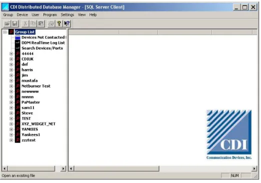
Start the DDM program either from the Start Menu or by clicking the DDM desktop shortcut. After you enter your username and password, the Opening screen is displayed.
Figure 5-1 Opening screen, Device/User View
5.2 Navigating the DDM software
The DDM software is menu-driven and easy to navigate. Dropdown menus list options.
5.3 Help
A brief description of the option and links is displayedwhen you rollover the option
5.4 Opening Screen
The options displayed in the menu bar depend on whether Device/User or Report View is selected. To switch views, click View in the Menu bar.
• Device/User view is the default view. It is used when adding or modifying
groups, devices, or users.
• Report View is selected when creating or viewing reports. Please refer to
section 12 for more information about Report View and reports.
5.4.1 Device View
The left pane of the screen displays the Group List. The right pane displays the names and certain attributes of the devices in a selected group.
Group List
The Group List is displayed in the left pane. The Group List may be expanded to
display all groups. The Groups displayed in the Group List will have been retrieved from the DDM Databases in the SQL Server.
The Device Not Contacted List is a list of all devices in the system that have not been
programmed and/or an error has occurred in the programming of a CDI device.
The DDM Real Time Log List is a list of all events that happen to a device in real
time. The device must have an IP card to communicate with the PC running the DDM program and the DDM Real Time Log must be enabled on the particular DDM PC. Each Group may be expanded to display information pertaining to the Groups: A Group may be compressed to display the only the Group name.
• Devices in the Group
• Client Encryptors in the Group
• Users in the Group
• User Locked List
• New Device Template for the Group
Devices and Attributes
The right pane lists the names and attributes of devices of a group.
Each field is described below:
• Device Name: Name given to the device when the device was added.
• Device Type: Type of device, such as Master Port Authority-88 with IP, UniGuard with IP, Port Authority 11SAM.
• Device Mode: Authentication mode of the device Standard (default)
Auto Authentication/Encryption – Connects to the device in an encrypted session but goes directly into the port list without a user ID/password authentication.
RSA SecurID Device – Allows the device to use RSA tokens for authentication.
• Host ID: A unique number used to identify the device in the DDM database. The serial number of the device is used as the Host ID.
• Program Status: Indicates whether the device can be contacted.
This field will be blank if there are no problems with the device. If there was a problem programming or contacting the device, it will display a message in red.
Examples:
No Contact From Device: A device that has heartbeat
properties configured and did not send the heartbeat “I’m Alive” message back to the DDM.
Invalid Communications: Failed to connect to the device. Error in Programming: Failed during programming of the device.
Invalid System Key: The system key that is programmed into the device is different than the device record in the DDM. Invalid System Password: The system password that is programmed into the device is different than the device record in the DDM.
• Version: Current firmware version of the device.
• Phone Number: Phone number used to contact the device.
• IP version: Current IP card firmware version.
• Def Credentials (Default Credentials):
PK: Indicates that both the device’s system password and system key
are at default levels.
P: Indicates the device’s system password is at a default level.
K: Indicates that the device’s system key is at a default level.
5.4.2 Viewing Device Status
To view the device status, right-click on the device name. The Device Properties screen will be displayed. The Device Status is displayed on the right-hand side. The Device status displays the program status of the device when the DDM attempts to connect to the device.
The program status may be Idle, In use, or Alarm. Each status type is described below:
Idle: The device is available to connect to the DDM
In Use: The device is already connected to the DDM
Alarm:: The device is in an alarm state and cannot be connected to the DDM.
To clear the device status, right-click on the status and select “Clear Device Status to Idle.” Select “Set Device Status to Alarm” to put the device into an alarm state.
5.4.3 Report View
Please refer to section 12 for more information about Report View and reports.
5.5 Installation and Set Up Overview
An overview of the steps to install and set up the DDM program are listed below. 1. Install the DDM application on a computer running Windows. The Install
Wizard will guide you through the steps. (Sections 3 and 4).
2. Create one or more groups. For each group, enter a Group name, the main device type, and the primary and secondary (optional) communication method. (Section 6)
3. Set up the device template. Any changes made to the device template will appear every time a device is added to the group. (Section 6.1)
4. Add devices or client encryptors to the group. Select the device type and enter a device name. Unless otherwise configured, the parameters in the device template will be used. (Sections 7 and 8).
5. Add users to the group. The users will be added to the database of the devices of the group. (Section 9)
Device Maximum number of users
UniGuard 150 Port Authority Sam 22/44 150
Port Authority Sam11 50
MultiGuard 1200
6. Set DDM system-wide parameters as required. These include adding device licenses, seat licenses for the DDM, and RSA licenses; assigning users as administrators; selecting the modem used to connect to CDI devices, setting up polling of devices, and other functions. (Section 10) 7. Reload (program) a single device, all devices of a group, or all devices
(Section 11)
8. Create reporting templates. Switch to report view to view reports and manage reports. (Section 12).
6 WORKING WITH GROUPS
A group is the collection of devices that can be accessed by a set of users. Groups can be defined by location, by region, or by another way that makes sense for your organization. Keep in mind that while a device may only be assigned to one group; a user may belong to multiple groups.
This section describes how to do the following:
• Add, delete, and rename a group
• Make modifications to all devices of the same type
• View a Real Time log
6.1 Add a Group
1. In the main screen, click on Group List. Click on Group in the Menu Bar. From the dropdown list, select Add New Group.
2. On the Group Attributes screen, enter the Group Name. You may also enter a brief description. After entering the appropriate information in the Group Attributes screen, click Ok to continue. The New Device Template for Group screen displays.
3. Set up the Device Template for a device type. From the dropdown list, select the Device Type. Click Next to continue
The Device Template establishes the default settings for the entire group. When a new device is added, the settings in the Device Template for that particular device type are used. You may later modify all settings of a device type in the Group Modifications screen.
4. Select the method for primary DDM communications and secondary DDM Communications. These settings determine the means by which the device and the DDM manager will communicate.
5. After you select the primary and secondary communications methods, the Device Template screen is displayed.
6. Click the tabs to enter device information, system options, communications settings, port options, and remote encryption. For a new or existing device, these settings may be modified in the Device Properties screen.
6.2 Rename a Group
Double-click on a Group Name or highlight the Group name and selecting Rename Group. The Group Attributes screen is displayed. Enter the new group name and description in the information field.
6.3 Delete a Group
Select “Delete Group” or highlight the Group and press the Delete key. You will be prompted to confirm that you want to
delete the group. Click Yes to continue or No to cancel the
Delete request.
CAUTION: Responding "Yes" to this prompt will delete the entire group and all of its device associations. The data will be unrecoverable.
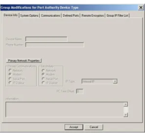
6.4 Group Modifications
Group Modifications allows you to modify certain settings of all devices of a particular
type in the selected group. The settings of Group Modifications will be applied to any device added to the group.
To display the Group Modifications screen, click on Group Modifications under the Group you wish to modify.
From the Select Device Type screen, select the device type that you wish to modify or select “All” to modify all device types. Selecting “All” essentially allows modifying only those parameters that common to all device types and are listed in the Device Template screen.
The parameters of the Group Modification screen differ slightly depending on the device. The parameters for each device type—UniGuard, Port Authority, and MultiGuard--are listed in the following sections. For a detailed description of each
parameter, please see the Devices chapter.
. 6.5 UniGuard Group Modifications
For more detailed information about the UniGuard parameters, please refer to the
Devices section.
UNIGUARD Group Modifications
Tab Parameters Description
Device info None
System Options User Security Level
Host “AT” Command Access) Host Dialout
Update System Password Update System Key Device Mode
Host DTR/RTS loss of Signal Time (secs)
First Message Delay Time Login Inactivity Time
User Security Level: Establishes the User ID as either User ID only or User ID and Password as the security method when logging in to the device.
Host “AT” Command Access: Enables the host to manage and access the device’s internal modem. If full host management of the device’s internal modem is necessary, this option should
UNIGUARD Group Modifications
Tab Parameters Description
be set for Enabled Transparency.
Host Dialout: Enable or disable the host ability to dial out using the device’s modem.
Device Mode:
Standard device (default) Security is enabled.
Auto Authentication: device only communicates with UniGuard clients in an encrypted session.
RSA SecurID ACM (act as an RSA ACM device)
RSA SecurID Device (first authenticates with a valid User ID and then
authenticates using RSA SecurID. Standard Device Bypass Security: Security is disabled on the device.
Update System Password: The system password is used by the DDM to access and program the device.
Update System Key: The default key used for all devices of this type. .The system key may be generated or entered.
Communications Modem Port Bits/Parity Modem Port Baud Rate Power Port Value Primary Defined Message Secondary Defined Message Host Connect Defined Message Extra AT Command Settings
Primary Defined Message: A user-defined message sent out when before the authentication process begins.
Secondary Defined Message: A user-defined message sent out after the first user response/prompt has been processed.
Host Connect: Only applies to UniGuard devices. A user-defined message sent out to the host port after successful user authentication. The user then connects to the host application.
Defined Ports None
Remote Encryptors
Edit Client ID Add Encryptor ID Delete Encryptor ID Select Encryptor IDs from database
Select from Client Database: Displays a list of IDs of clients that are allowed to access devices that belong to this group.
Group IP Filter List*
Add IP Filter Edit IP Filter Delete IP Filter
The IP Filter address ranges can be set for inclusion mode and exclusion mode.
UNIGUARD Group Modifications
Tab Parameters Description
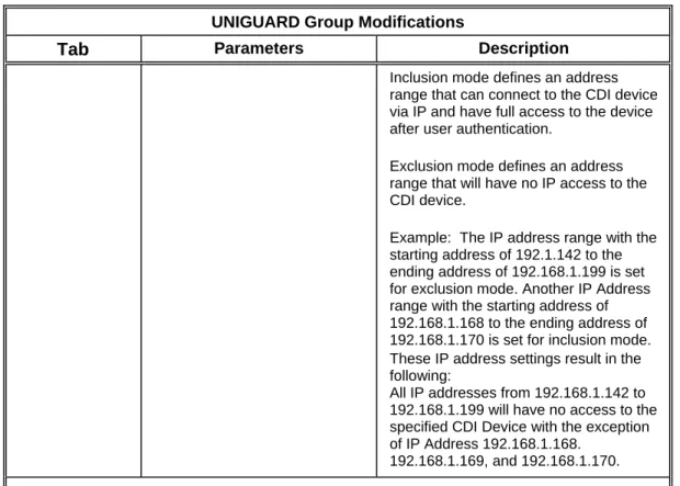
Inclusion mode defines an address range that can connect to the CDI device via IP and have full access to the device after user authentication.
Exclusion mode defines an address range that will have no IP access to the CDI device.
Example: The IP address range with the starting address of 192.1.142 to the ending address of 192.168.1.199 is set for exclusion mode. Another IP Address range with the starting address of 192.168.1.168 to the ending address of 192.168.1.170 is set for inclusion mode. These IP address settings result in the following:
All IP addresses from 192.168.1.142 to 192.168.1.199 will have no access to the specified CDI Device with the exception of IP Address 192.168.1.168.
192.168.1.169, and 192.168.1.170.
*The Group IP Filter List is for CDI devices that have a CDI internal IP card at version 2.00 or above.
6.6 Port Authority Group Modifications
For more detailed information about Port Authority parameters, please refer to the
Devices chapter.
PORT AUTHORITY Group Modifications
Tab Parameters Description
Device info screen
None
System Options User Security Level Update System Password Update System Key Device Mode (Type)) First Message Delay Time Inactivity Time
Host DTR/RTS loss of Signal Time (secs)
First Message Delay Time Login Inactivity Time
User Security Level: Establishes the User ID as either User ID only or User ID and Password as the security method when logging in to the device.
Update System Key: This is the default key used for all devices of this type. The system key may be generated or entered.
Standard device (default) Security is enabled.
PORT AUTHORITY Group Modifications
Tab Parameters Description
Auto Authentication: device only communicates with UniGuard clients in an encrypted session. RSA SecurID ACM (act as an RSA ACM device)
RSA SecurID Device (first authenticates with a valid User ID and then authenticates using RSA SecurID.
Standard Device Bypass Security: Security is disabled on the device.
Communications Modem Port Bits/Parity Modem Baud Rate Primary Defined Message Secondary Defined Message Send AT Command
Primary Defined Message: A user-defined message sent out before the authentication process begins.
Secondary Defined Message: A user-defined message sent out after the first user response/prompt has been processed.
Defined Ports Control Mimicking Modem Connect Message
Remote Encryptors
Edit Client ID Add Client ID Delete Client ID
Select Client IDs from database
Displays a list of IDs of clients that are allowed to access devices that belong to this group.
Group IP Filter List*
Add IP Filter Edit IP Filter Delete IP Filter
The IP Filter address ranges can be set for inclusion mode and exclusion mode.
Inclusion mode defines an address range that can connect to the CDI device via IP and have full access to the device after user authentication.
Exclusion mode defines an address range that will have no IP access to the CDI device.
Example: The IP address range with the starting address of 192.1.142 to the ending address of 192.168.1.199 is set for exclusion mode. Another IP Address range with the starting address of 192.168.1.168 to the ending address of 192.168.1.170 is set for inclusion mode.
Result of these IP address settings: All IP addresses from
PORT AUTHORITY Group Modifications
Tab Parameters Description
192.168.1.142 to 192.168.1.199 will have no access to the specified CDI Device with the exception of IP Address 192.168.1.168.
192.168.1.169, and 192.168.1.170.
*The Group IP Filter List is for CDI devices that have a CDI internal IP card at version 2.00 or above.
6.7 MultiGuard Group Modifications
For more detailed information about the MultiGuard parameters, please refer to the Devices chapter.
MULTIGUARD Group Modifications
Tab Parameters Description
Device info screen None
System Options User Security Level Host “AT” Command Access Update System Password Device Mode (Type) Update System Key First Message Delay Time Host DTR/RTS loss of Signal Time (secs)
First Message Delay Time Login Inactivity Time
User Security Level: Establishes the User ID as either User ID only or User ID and Password as the security method when logging in to the device.
Update System Key: The system key may be generated or entered. This is the default key used for all devices of this type.
Standard device (default) Security is enabled.
Auto Authentication: device only communicates with UniGuard clients in an encrypted session.
RSA SecurID ACM (act as an RSA ACM device)
RSA SecurID Device (first authenticates with a valid User ID and then
authenticates using RSA SecurID. Standard Device Bypass Security: Security is disabled on the device.
Communications Primary Messages: Primary Secondary
Extra AT Command Settings
Primary Defined Message: A user-defined message sent out when before the authentication process begins.
Secondary Defined Message: A user-defined message sent out after the first user response/prompt has been processed.
MULTIGUARD Group Modifications
Tab Parameters Description
Defined Ports None
Remote Encryptors
None
Group IP Filter List*
Add IP Filter Edit IP Filter Delete IP Filter
The IP Filter address ranges can be set for inclusion mode and exclusion mode.
Inclusion mode defines an address range that can connect to the CDI device via IP and have full access to the device after user authentication.
Exclusion mode defines an address range that will have no IP access to the CDI device.
Example: The IP address range with the starting address of 192.1.142 to the ending address of 192.168.1.199 is set for exclusion mode. Another IP Address range with the starting address of 192.168.1.168 to the ending address of 192.168.1.170 is set for inclusion mode.
These result in the following:
All IP addresses from 192.168.1.142 to 192.168.1.199 will have no access to the specified CDI Device with the exception of IP Address 192.168.1.168.
192.168.1.169, and 192.168.1.170.
The Group IP Filter List is for CDI devices that have a CDI internal IP card at version 2.00 or above.
6.8 Real Time Log List
The DDM Real Time Log List is a list of all events that happen to a device in real time. The device must have an IP card to communicate with the PC running the DDM applications and the DDM Real Time Log must be enabled on the particular DDM PC.
These logs can only be viewed from the Real Time Log List. The items are color-coded to indicate the severity of the real time log item.
REAL TIME LOG ALERT SEVERITY LEVELS
SEVERITY COLOR
ALERT Green INFORMATION Blue DEBUG Blue
WARNING Orange
EMERGENCY Red
CRITICAL Red ERROR Red NOTICE Red
Each entry in the log has the following information: Date/Time, Device Name, Facility, Severity, Message, and Source IP Address.
6.9 Enabling the Real Time Log List
The Real Time log list must be enabled before you can view it.
1. Click on SETTINGS in the Menu bar. From the dropdown menu, select Setup. 2. In the Setup window, click the checkbox titled “Enable DDM Real Time Log.” 3. Modify the default DDM Real Time Log Port value if necessary. The default port
is 514.
4. Click OK to enable the Real Time Log option and exit the Setup window. When this option has been enabled, the IP address of the DDM will appear in the title bar of the Setup window.
5. After enabling the DDM Real Time Log option and exiting the Setup window, the DDM Real Time Log listener will be activated. As logs come in, they will be
validated Select DDM RealTime Log List under Group List to view the log. All
new log items will be inserted in the view list in real time. and inserted into the DDM databases (DDMSysLog and DDMLog).
6.9.1 Printing, Saving and Deleting the DDM Real Time Log
The DDM Real Time Log can be printed or saved to a file. To print or save the file, highlight any line on the DDM Real Time Log and click on the GROUP in the menu bar of the DDM window. From the list displayed, select the appropriate action--Print DDM Real Time Log or Save DDM Real Time Log to file.
If Save DDM Real Time Log has been selected, choose the folder in which the file is
to be saved and enter the filename in the displayed Save As window.
6.9.2 Deleting items from the DDM Real Time Log
To delete a real-time log, click Devices in the menu bar and then select Delete DDM
Real Time Log. The real-time log of DDM actions will be deleted. Once deleted, it
7 DEVICES
This section explains how to add to a device to group, remove a device from a group, and configure the properties of a specific device.
For information about adding UniGuards and Port Authority devices as client encryptors, may be added to a group as client encryptors, please refer to the Client Encryptors chapter.
7.1 Add a device to a group
A device may be added to group by one of the following ways:
• Duplicate a device
• Move a device from one group to another
• Use the Add Device Wizard
7.1.1 Duplicate a Device
Display the Device List by double-clicking the Device Leaf of the Selected Group; the device list for this group will be displayed. To duplicate a device, click on the device and drag and drop it to the new Group. From the Duplicate or Move Device screen, select Duplicate Device.
When a device is duplicated, the device settings will be duplicated only. The group parameters for the device will be dependent on the group to which it is attached.
7.1.2 Move a Device
To move a device from one group to another, click on the device and drag it to the new group. The Duplicate or Move Device screen will be displayed. From this screen, select Move device.
When device is moved from one group to another, the device settings remain the same but the group setting for the device changes. For instance, the device will be attached to the users and client IDs attached of this group only.
7.1.3 Use the Device Wizard to add a device
The Add Device Wizard guides you through the steps to add a new device. When a new device is added to a group, the New Device Template is applied, which was
created when the Group was created. The New Device Template uses the group parameters as a basis for the device properties.
1. Click on the name of the group to which you want to add the device.
2. Click on Devices in the menu bar and select Add New Device. The New Device Properties screen is displayed. Alternatively, you may double-click the Device leaf under the Group name to display the New Device Properties screen.
Alternatively, click to highlight a device name in the right panel. Right-click the device name and a menu with device options is displayed. Select the Add New Device option to add a device.
3. From the New Device Properties screen, select the device type from the scroll down list. Enter a name for the device.
5. The wizard displays the Connection screen. From the scroll-down list, select the primary and secondary method by which the device will communicate with the DDM. For each communication method, enter the IP address, port, and other requested information.
6. On the next screen, the wizard then prompts you to enter a password for the
device. You also have the option to use RSA SecurID. Select Yes to use RSA
SecurID. .
7. Click Finish to complete the procedure.
8. After the device parameters and all the users for this device have been entered, the information can be loaded to the device from the DDM. To do this, select Reset Device from the Program menu.. This will reset the device to the default parameters and load the new system and port options. It will clear the device’s User database and reprogram it with the latest User database for this Group. If you are adding several devices to a group, add all the devices first, and then select Reset Group from the Program menu.
7.1.4 Modifying Device Properties
You can change the properties of an existing device. To do this, double-click on the device in the Device List view to display the Device Properties screen. You may then change the Device Info properties or click on the appropriate tab to modify other settings.
Alternatively, you can click on Device in the Device List view, then click on Device in the menu bar. Select Display/Rename Device to display the Device Properties screen.
7.1.5 Renaming a Device
The name of an existing device can be changed by highlighting the existing device in the device list and then selecting, Display/Rename Device, or by double clicking on the device in the Device List view.
7.1.6 Deleting a Device
To delete a device, highlight the existing device in the Device List view and then click on Device in the menu bar. Select Delete device.
You can also click on the device in the device list and then press the delete key. "Display/Rename Device Attributes" will display the Device Properties screen and "Delete Device" will delete the device from the group after the appropriate warning prompt.
7.2 Configuring a Device
The Device Properties screen enables you to configure devices managed by the DDM. You can display this screen by double-clicking on the device name from the device list in the Main screen.
You can also display the Device Properties screen by clicking on the specific device name. From the menu bar, click Devices and then Display Device Attributes. The Device Properties screen has five tabs that display screens for entering parameters to set up for devices managed by DDM. Not all tabs apply to all device types. The fields on the screens depend on the device type selected.
• Device Info
• System Options
• Communications
• Defined Ports (for Port Authority, Port Authority SAM or a
MultiGuard devices only)
• Remote Encryptions
7.2.1 Device Info Screen
The Device Info screen enables you to enter reference information about the device being added and define the communication paths by which DDM will access the device.
To display the Device Info screen, Right click on a device. From the menu, select Edit Device (or double click on device), and then click the Primary Network Properties button
Device Type: Required. Select the device type from the dropdown list. Available devices include the Port Authority SAM (-11, -22, -44), UniGuard, Port Authority (-88, -44 or –84), or a MultiGuard. The default setting is UniGuard.
Device Name: Required; for reference to the device’s ID, such as company, location, etc
Device Status link: Click on this link to view whether the program status of the device.
IDLE: Device is ready to connect to the DDM IN USE: Device is connected to the DDM
ALARM: Device is in the alarm state and can not be connected to the DDM
To clear a device or to put in an alarm state, click the status link. Select Clear Device
Status to put the device in an idle state. Select Set Device Status to Alarm to put the
device in an alarm state.
NOTE: When the DDM is communicating with a CDI device, device the status will read IN SE. If the device is not being used and the status still reads INUSE, click on the status and select Clear Device Status to IDLE.
Serial Number: No entry is necessary. When the DDM accesses the device, it retrieves the device’s serial number and adds it to the DDM database.
RSA SecurID Enable: Set this to make the device act as an ACM device and as a replacement for an RSA SecurID “ACM” unit. The device can also be an RSA SecurID unit (CDI device/ACM device). The serial number field will display the RSA Serial Number.
Version: No entry is necessary. When the DDM accesses the device, it retrieves the device version and adds it to the DDM Database.
Primary Polling Device: This unit will be polled first when the Group is being polled if this option is selected. A group need not have a Primary Polling Device assigned. Each group can have one device that will be the primary device of Group.
Asset Tag: Optional. Enter additional information to better define the CDI device. A maximum of 20 characters may be entered for this field.
Information: Optional. Enter additional reference information.
Primary Communications: Determines whether the primary method of accessing the device will be via a network, dial-up phone lines through a modem or through the serial port. If Serial Port is selected, you will be prompted to enter the COM port number the DDM will use to communicate with this device.
Secondary Communications: Optional; Determines the secondary path of communication. If the Serial Port is selected, a window will request a COM port number that the DDM will use to communicate with this device.
Time Offset: Optional; The hours ahead of or behind local time at the Network Administrator’s location. The offset is used in report generation and to set the time of the remote devices.
Example: If the DDM Manager is located in New York (EST) and the device
is located in Los Angles (PT) then the offset will equal –3 (hours).
Primary Network Properties: Click this button to configure the parameters of the IP card of a device that has IP capabilities, allowing access to the device through a network.
RSA SecurID Enable: Click the RSA SecurID Enable button
to display the Enter the Device Serial Number screen. In this
screen, you can set the device as an RSA device. For RSA SecuID ACM only: If the device is a replacement for an RSA SecurID “ACM” unit, select this setting makes the UniGuard act like an ACM device.
RSA SecurID unit: The device can also be an RSA SecurID unit (CDI device/ACM device). The device will authenticate with an RSA Token and non-RSA user types.
Use Dialing Options: Required if the device will be dialing a country or region requiring a Country or Region dial code.
Country/Region List: (Displayed only if Use Dialing Options is enabled). A list of countries and their associated country codes. If used, dialing options will be enabled and the list will define the devices destinations country code.
Dialout Modem Number: Required for devices that will be accessed via phone lines. When typing the phone number do not put in any spaces.
IP Type, Internal/External: IP Type defines the type of IP card, Internal or external.
External IP - The device is not set for an internal CDI IP card but it can be programmed by the DDM through an external IP connection. For example, the link port of a UniGuard (no IP card) can be connected to a Cisco Router's AUX port. To connect to the Cisco Router AUX port a connection would be made to the Cisco Router via an IP address (ex. 192.168.0.176 4001). The DDM then can program (contact) the device via Network communications using this IP address.
The following is only displayed in the devices that have the IP Option.
Use as IP Dialout Connection (Optional) with internal IP card or external IP access device.
The IP Dialout allows access to a modem for Dialout purposes but first connects to the modem via a Network IP Address (virtual modem port, e.g. Terminal Server, UniGuard device (version 8.13 and up)).
If device type is a UniGuard and it has a network address, it can be used by the DDM as an IP Dialout connection by checking the Use as IP Dialout Connection option in the Device Properties window of the UniGuard.
7.2.2 Country Dialing Using the DDM
Each device can be contacted by the DDM via Modem or IP Dial out communications using the dialing properties of the PC.
If the option “Use Dial Options” is enabled in the Device Properties screen, the device can be set for a (destination) Country/ Region code by selecting the Country Name and corresponding Country Code from Country/region list in the Device Info screen. When dialing the device, the DDM PC will use the latest location information, the dialing properties of the PC, the destination country code, and the phone number defined in the DDM device’s properties.
Example of Country Dialing Using the DDM
A device in the DDM database is to be dialed by two DDM PCs, one located in the US and the other located in the UK. They are connected to a SQL Server 2000 database located in the UK. We want to be able dial to the device, which is located in Japan, from both DDM locations. In each DDM location, the DDM can be set to use a particular location name.
For the device in Japan, enable Use Dialing Options in the Device Properties screen. After User Dialing Options has been enabled, select Japan as the country from the Country/region list [ex. Japan (81)]. You will need to enter the telephone number of the device (ex. “262 5551212”) for the DDM to dial it.
Device located in Japan dialed by
DDM client in the UK
Device located in Japan dialed by
DDM client in the US
Long Distance Access prefix = 787 (if defined) International Rule for UK is 00
DDM dials 787 00 81 262 5551212.
Long Distance Access prefix = 987 (if defined) International Rule for US is 011
DDM dials 987 011 81 262 5551212
7.3 Setting the Network Properties of a Specific Device
The Primary Networks Properties screen enables you to configure the network properties of a specific device.
This screen is accessed from the Device Properties screen. To display the Primary Networks Properties screen, click the Primary Network Properties button on the Device Properties screen.
7.3.1 Network Properties, IP Configuration
The Network Properties screen, IP Configuration allows for the configuration of an IP Port including a Gateway Address if required.
Device IP Address: Required. Address of the IP Port.
Port No: Port number used to communicate from the Network side “ex. Telnet Port Number.” To update the port number, click the Update Port
Number button. Break commands can only be sent out on Port 23 (Telnet Port).
Use Default Port for DDM Programming: Click to enable the DDM to use of the device default port for programming.
NAT Address: Required: Enter the NAT Address. Normally this is the same as the Device IP address. The purpose for this address is for the devices of an Internal network to be identified by one IP address when routed to a different network.
Subnet Mask: Required: The Subnet Mask is a mask used to determine to which subnet an IP address belongs by filtering with this bit pattern. If your host PC is using the wrong subnet mask you will not be able to correctly identify all users on that subnet and many users could be unreachable by your computer. The subnet mask is defaulted to work with an 8-bit host address. For any other host bit address, you must change the subnet mask to the proper setting.
Gateway Address Optional: The router/gateway address that allows you access to other network segments. This address must be within the local network
Assigned Client PPP Address (Optional): Enter the Assigned Client PPP Address. The CDI device will send a request to the host at the PPP address entered, establishing a PPP session.
Hardware Address: If the device will be programmed through a modem/dial-up connection you DO NOT NEED to enter the Hardware address, DDM will automatically receive it when dialed in.
IMPORTANT: If the device will be programmed through the IP Network you must enter the hardware address in the “Hardware Address” field.
SysLog IP Address: Optional: Enter the SysLog IP Address. If a Syslog Server application is running on your network, CDI Devices can report audit trail messages back to the Syslog Server for monitoring purposes.
Backup SysLog Server: Optional. Enter the Backup SysLog Server address.
SysLog IP Port: Optional: Enter the SysLog IP Port that the CDI Device can use for communication purposes.
Radius IP Address: Optional: Enter the Radius IP Address
Backup Radius Address: Optional. Enter a backup IP address for the Radius server.
Radius IP Port Number: Optional. Enter the Radius IP Port Number
Radius Key Optional: Enter the Radius Key. This can be up to 128 characters.
7.3.2 DDM Heartbeat Attributes
The DDM Heartbeat is an automatic “I’m alive” message that is sent periodically by a remote device to a DDM workstation enabled for real time logs. If heartbeat
messages (or any other messages) are not sent to the DDM within the given time interval, a “No Contact From Device” alarm will be triggered for this device. The CDI device must have an Internal IP card running version 4.01 or above.
DEVICE PROPERTIES SCREEN ÆDEVICE INFO TAB ÆPRIMARY NETWORKS PROPERTIES BUTTON Æ
DDMHEARTBEAT BUTTON Æ HEARTBEAT ATTRIBUTES SCREEN
Example: If the Maximum Number of Missed heartbeats is set to three beats and the Heartbeat Message Interval to 60 minutes, a “No Contact From Device” error is generated by the DDM each time the device does not respond with 180 minutes (3 x 60).
Tip: A screen explaining the DDM heartbeat attributes can be displayed by clicking the Help button of the DDM Heartbeat Attributes window.
DDM Real-Time Log Address: IP address of the DDM workstation that is enabled for Real Time logs.
DDM Real-Time Log Port: The port number associated with the DDM Real-Time Log Address. The port number can range from 5000 and up. This port number will be set from the DDM workstation that is enabled for DDM Real Time Logs.
Max No. Of Missed Heartbeats: Number of missed heartbeats that will trigger an alarm from the DDM workstation that is set for real time logs. The default is zero.
Heartbeat Message Interval: The time in minutes between heartbeats sent by the remote device. For example, an interval of 60 would generate a heartbeat once an hour by the remote device. This interval would be programmed into the device. The default is zero.
Disable Heartbeat Attributes: Check the Disable Heartbeat Values box to disable the DDM Heartbeat for this device
7.3.3 DNS Attributes
Click this button to display the DNS attributes for this device.
7.3.4 SNMP Attributes
Click this button to display the SNMP attributes for the device. Enter the primary and backup SNMP IP addresses and the primary and backup SNMP port numbers.
7.3.5 Network Properties (versions below 4.01)
The Network Properties screen for CDI devices with an internal IP card running a version below 4.01 have the fields listed in previous section as well as the following fields.
Use IP Address for Device Programming: This defines the IP address to be used by the DDM for the remote programming of the device.
Enable ID/Password Authentication option. When enabled (check marked) all network connections to this IP address (e.g. 192.168.000.168) will first need to
authenticate (ID/Password authentication) successfully before accessing the CDI device. This is only for CDI devices with the CDI internal IP Card version 3.03 and above.
The IP Admin User ID and IP Admin Password fields are used for ID/Password Authentication and can be up to 10 characters. If the Enable ID/Password Authentication option is enabled, the Radius fields will be disabled.
The Update ID button for the IP Admin User ID
field and the Update Password buttons for the
IP Admin Password field will always be displayed when editing an existing device.
The IP Admin User ID can only be updated using the Update ID button. The IP Admin
Password can only be updated using the Update Password button.
The Update Port Number button for the IP Port
number field will always be displayed when editing an existing device. The IP Port number can only be updated using the Update Port Number button.
7.3.6 Network Properties (IP type set for external)
The Network Properties screen for external IP type device has three fields. The fields are described below.
Device IP Address: Enter the IP address of the IP card.
Port No: Enter the port number for communication from the Network side, for example. “Telnet Port number.”
NAT Address (Network Address Translation): Address that will allow multiple devices to use a single IP address to access the Internet.
7.4 System Options
The parameters on this screen enables you to set user security levels, system password and key information, and first message delay time. The System Options screen may have different parameters depending on the device.
User Security Level: Select the security method used when a user logs on to the device. The two methods available are User ID and User ID and Password.
IP Dialout (for devices with the IP Option). This enables the device to use the network for programming and communication purposes. You may select IP dialout with or without encryption, or you may disable (not allow) IP dialout.
Sys Password: To change the system password of an existing device, click on the Update Password button to display the System Password Update screen. Enter the new password in both fields. For security purposes, the password will be displayed as asterisks.
System Password: Click Update Password to change the system password.
Update System Key: To change the System Key,
click the Update System Key button to display the
System Key Update screen. You may enter a key
or click “Generate” to have the system create the key.
A new System key may be set for a single device, for all devices in a group, or set all devices of a particular type in a group.
First Message Delay Time (sec): Enter the time in seconds until the “Enter User ID” prompt is displayed.
Login Inactivity Time: Enter the time in seconds after which the login call is
disconnected if there is no data flow between the user and host
7.4.1 Port Authority SAM Host Devices
This section applies only to SAM host devices.
Sam Client-Host Authentication (Only Port Authority SAM Host Device): This setting determines how the Host SAM Device will authenticate with the SAM Client Device.
Disabled: No authentication takes place.
User Authentication: The authentication process starts after the connection is up and the user ID has been entered.
Auto Authentication: The authentication process starts as soon as the connection is up.