SUSE Linux Enterprise
Server
www.novell.com 10 SP3
Heartbeat
All content is copyright © Novell, Inc. Legal Notice
This manual is protected under Novell intellectual property rights. By reproducing, duplicating or distributing this manual you explicitly agree to conform to the terms and conditions of this license agreement.
This manual may be freely reproduced, duplicated and distributed either as such or as part of a bundled package in electronic and/or printed format, provided however that the following conditions are ful-filled:
That this copyright notice and the names of authors and contributors appear clearly and distinctively on all reproduced, duplicated and distributed copies. That this manual, specifically for the printed format, is reproduced and/or distributed for noncommercial use only. The express authorization of Novell, Inc must be obtained prior to any other use of any manual or part thereof.
For Novell trademarks, see the Novell Trademark and Service Mark listhttp://www.novell .com/company/legal/trademarks/tmlist.html. * Linux is a registered trademark of Linus Torvalds. All other third party trademarks are the property of their respective owners. A trademark symbol (®, ™ etc.) denotes a Novell trademark; an asterisk (*) denotes a third party trademark. All information found in this book has been compiled with utmost attention to detail. However, this does not guarantee complete accuracy. Neither Novell, Inc., SUSE LINUX Products GmbH, the authors, nor the translators shall be held liable for possible errors or the consequences thereof.
Contents
About This Guide v
1 Overview 1
1.1 Product Features . . . 1
1.2 Product Benefits . . . 2
1.3 Cluster Configurations . . . 5
1.4 Heartbeat Cluster Components . . . 8
1.5 Architecture . . . 8
2 Installation and Setup 13 2.1 Hardware Requirements . . . 14
2.2 Software Requirements . . . 14
2.3 Shared Disk System Requirements . . . 14
2.4 Preparations . . . 15
2.5 Installing Heartbeat . . . 17
2.6 Configuring STONITH . . . 21
3 Setting Up a Simple Resource 25 3.1 Configuring a Resource with the Heartbeat GUI . . . 25
3.2 Manual Configuration of a Resource . . . 27
4 Configuring and Managing Cluster Resources 29 4.1 Graphical HA Management Client . . . 29
4.2 Creating Cluster Resources . . . 31
4.3 Configuring Resource Constraints . . . 33
4.5 Specifying Resource Failback Nodes (Resource Stickiness) . . . 34
4.6 Configuring Resource Monitoring . . . 35
4.7 Starting a New Cluster Resource . . . 36
4.8 Removing a Cluster Resource . . . 36
4.9 Configuring a Heartbeat Cluster Resource Group . . . 37
4.10 Configuring a Heartbeat Clone Resource . . . 40
4.11 Migrating a Cluster Resource . . . 41
5 Manual Configuration of a Cluster 43 5.1 Configuration Basics . . . 44
5.2 Configuring Resources . . . 47
5.3 Configuring Constraints . . . 52
5.4 Configuring CRM Options . . . 55
5.5 For More Information . . . 60
6 Managing a Cluster 61 7 Creating Resources 103 7.1 STONITH Agents . . . 103
7.2 Resource Agents . . . 104
7.3 Writing OCF Resource Agents . . . 104
8 Troubleshooting 107
A HB OCF Agents 109
About This Guide
Heartbeat is an open source clustering software for Linux. Heartbeat ensures high availability and manageability of critical network resources including data, applications, and services. It is a multinode clustering product that supports failover, failback, and migration (load balancing) of individually managed cluster resources.
This guide is intended for administrators given the task of building Linux clusters. Basic background information is provided to build up an understanding of the Heartbeat ar-chitecture. Setup, configuration, and maintenance of a Heartbeat cluster are covered in detail. Heartbeat offers a graphical user interface as well as many command line tools. Both approaches are covered in detail to help the administrators choose the appropriate tool matching their particular needs.
NOTE
This manual covers Heartbeat version 2 and higher. Whenever the authors use the term “Heartbeat”, they refer to Heartbeat 2, even when no explicit version number is given.
This guide contains the following:
Overview
Before starting to install and configure your cluster, learn about the features Heartbeat offers. Familiarize yourself with the Heartbeat terminology and its basic concepts.
Installation and Setup
Learn about hardware and software requirements that must be met before you can consider installing and running your own cluster. Perform a basic installation and configuration using the Heartbeat graphical user interface.
Setting Up a Simple Resource
After you have completed the basic cluster configuration, check out a quick step-by-step instruction of how to configure an example resource. Choose from a GUI-based approach or a command line-driven one.
Configuring and Managing Cluster Resources
Managing resources encompasses much more than just the initial configuration. Learn how to use the Heartbeat graphical user interface to configure and manage resources.
Manual Configuration of a Cluster
Managing resources encompasses much more than just the initial configuration. Learn how to use the Heartbeat command line tools to configure and manage re-sources.
Managing a Cluster
Heartbeat provides a comprehensive set of command line tools to assist you in managing your own cluster. Get to know the most important ones for your daily cluster management tasks.
Creating Resources
In case you consider writing your own resource agents for Heartbeat or modifying existing ones, get some detailed background information about the different types of resource agents and how to create them.
Troubleshooting
Managing your own cluster requires you to perform a certain amount of troubleshoot-ing. Learn about the most common problems with Heartbeat and how to fix them. Terminology
Refer to this chapter for some basic Heartbeat terminology that helps you understand the Heartbeat fundamentals.
1 Feedback
We want to hear your comments and suggestions about this manual and the other doc-umentation included with this product. Please use the User Comments feature at the bottom of each page of the online documentation and enter your comments there.
2 Documentation Updates
Expect updates to this documentation in the near future while it is extended to match the capabilities of the software itself and to address more and more use cases. By using the User Comments feature described in Section 1, “Feedback” (page vi), let us know on which aspects of Heartbeat this guide should elaborate.
For the latest version of this documentation, see the SLES 10 SP3 documentation Web
site athttp://www.novell.com/documentation/sles10.
3 Documentation Conventions
The following typographical conventions are used in this manual: • /etc/passwd: filenames and directory names
• placeholder: replaceplaceholderwith the actual value • PATH: the environment variable PATH
• ls,--help: commands, options, and parameters
• user: users or groups
• Alt,Alt+F1: a key to press or a key combination; keys are shown in uppercase as on a keyboard
• File, File > Save As: menu items, buttons
• ►amd64 ipf: This paragraph is only relevant for the specified architectures. The arrows mark the beginning and the end of the text block.◄
►ipseries s390 zseries: This paragraph is only relevant for the specified
architec-tures. The arrows mark the beginning and the end of the text block.◄
• Dancing Penguins (Chapter Penguins, ↑Another Manual): This is a reference to a chapter in another manual.
1
Overview
Heartbeat is an open source server clustering system that ensures high availability and manageability of critical network resources including data, applications, and services. It is a multinode clustering product for Linux that supports failover, failback, and mi-gration (load balancing) of individually managed cluster resources. Heartbeat is shipped with SUSE Linux Enterprise Server 10 and provides you with the means to make virtual machines (containing services) highly available.
This chapter introduces the main product features and benefits of Heartbeat. Find sev-eral exemplary scenarios for configuring clusters and learn about the components making up a Heartbeat version 2 cluster. The last section provides an overview of the Heartbeat architecture, describing the individual architecture layers and processes within the cluster.
1.1 Product Features
Heartbeat includes several important features to help you ensure and manage the availability of your network resources. These include:
• Support for Fibre Channel or iSCSI storage area networks
• Multi-node active cluster, containing up to 16 Linux servers. Any server in the cluster can restart resources (applications, services, IP addresses, and file systems) from a failed server in the cluster.
• A single point of administration through either a graphical Heartbeat tool or a command line tool. Both tools let you configure and monitor your Heartbeat cluster. • The ability to tailor a cluster to the specific applications and hardware infrastructure
that fit your organization.
• Dynamic assignment and reassignment of server storage on an as-needed basis. • Time-dependent configuration enables resources to fail back to repaired nodes at
specified times.
• Support for shared disk systems. Although shared disk systems are supported, they are not required.
• Support for cluster file systems like OCFS 2.
• Support for cluster-aware logical volume managers like EVMS.
1.2 Product Benefits
Heartbeat allows you to configure up to 16 Linux servers into a high-availability cluster, where resources can be dynamically switched or moved to any server in the cluster. Resources can be configured to automatically switch or be moved in the event of a re-source server failure, or they can be moved manually to troubleshoot hardware or balance the workload.
Heartbeat provides high availability from commodity components. Lower costs are obtained through the consolidation of applications and operations onto a cluster. Heartbeat also allows you to centrally manage the complete cluster and to adjust re-sources to meet changing workload requirements (thus, manually “load balance” the cluster).
An equally important benefit is the potential reduction of unplanned service outages as well as planned outages for software and hardware maintenance and upgrades. Reasons that you would want to implement a Heartbeat cluster include:
• Increased availability • Improved performance
• Low cost of operation • Scalability
• Disaster recovery • Data protection • Server consolidation • Storage consolidation
Shared disk fault tolerance can be obtained by implementing RAID on the shared disk subsystem.
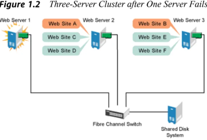
The following scenario illustrates some of the benefits Heartbeat can provide. Suppose you have configured a three-server cluster, with a Web server installed on each of the three servers in the cluster. Each of the servers in the cluster hosts two Web sites. All the data, graphics, and Web page content for each Web site are stored on a shared disk subsystem connected to each of the servers in the cluster. The following figure depicts how this setup might look.
Figure 1.1 Three-Server Cluster
During normal cluster operation, each server is in constant communication with the other servers in the cluster and performs periodic polling of all registered resources to detect failure.
Suppose Web Server 1 experiences hardware or software problems and the users de-pending on Web Server 1 for Internet access, e-mail, and information lose their connec-tions. The following figure shows how resources are moved when Web Server 1 fails.
Figure 1.2 Three-Server Cluster after One Server Fails
Web Site A moves to Web Server 2 and Web Site B moves to Web Server 3. IP addresses and certificates also move to Web Server 2 and Web Server 3.
When you configured the cluster, you decided where the Web sites hosted on each Web server would go should a failure occur. In the previous example, you configured Web Site A to move to Web Server 2 and Web Site B to move to Web Server 3. This way, the workload once handled by Web Server 1 continues to be available and is evenly distributed between any surviving cluster members.
When Web Server 1 failed, Heartbeat software • Detected a failure
• Remounted the shared data directories that were formerly mounted on Web server 1 on Web Server 2 and Web Server 3.
• Restarted applications that were running on Web Server 1 on Web Server 2 and Web Server 3
• Transferred IP addresses to Web Server 2 and Web Server 3
In this example, the failover process happened quickly and users regained access to Web site information within seconds, and in most cases, without needing to log in again.
Now suppose the problems with Web Server 1 are resolved, and Web Server 1 is returned to a normal operating state. Web Site A and Web Site B can either automatically fail back (move back) to Web Server 1, or they can stay where they are. This is dependent on how you configured the resources for them. There are advantages and disadvantages to both alternatives. Migrating the services back to Web Server 1 will incur some down-time. Heartbeat also allows you to defer the migration until a period when it will cause little or no service interruption.
Heartbeat also provides resource migration capabilities. You can move applications, Web sites, etc. to other servers in your cluster without waiting for a server to fail. For example, you could have manually moved Web Site A or Web Site B from Web Server 1 to either of the other servers in the cluster. You might want to do this to upgrade or perform scheduled maintenance on Web Server 1, or just to increase performance or accessibility of the Web sites.
1.3 Cluster Configurations
Heartbeat cluster configurations might or might not include a shared disk subsystem. The shared disk subsystem can be connected via high-speed Fibre Channel cards, cables, and switches, or it can be configured to use iSCSI. If a server fails, another designated server in the cluster automatically mounts the shared disk directories previously mounted on the failed server. This gives network users continuous access to the direc-tories on the shared disk subsystem.
IMPORTANT: Shared Disk Subsystem with EVMS
When using a shared disk subsystem with EVMS, that subsystem must be con-nected to all servers in the cluster.
Typical Heartbeat resources might include data, applications, and services. The following figure shows how a typical Fibre Channel cluster configuration might look.
Figure 1.3 Typical Fibre Channel Cluster Configuration
Although Fibre Channel provides the best performance, you can also configure your cluster to use iSCSI. iSCSI is an alternative to Fibre Channel that can be used to create a low-cost SAN. The following figure shows how a typical iSCSI cluster configuration might look.
Figure 1.4 Typical iSCSI Cluster Configuration
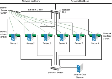
Although most clusters include a shared disk subsystem, it is also possible to create a Heartbeat cluster without a share disk subsystem. The following figure shows how a Heartbeat cluster without a shared disk subsystem might look.
Figure 1.5 Typical Cluster Configuration Without Shared Storage
1.4 Heartbeat Cluster Components
The following components make up a Heartbeat version 2 cluster:
• From 2 to 16 Linux servers, each containing at least one local disk device. • Heartbeat software running on each Linux server in the cluster.
• Optional: A shared disk subsystem connected to all servers in the cluster.
• Optional: High-speed Fibre Channel cards, cables, and switch used to connect the servers to the shared disk subsystem.
• At least two communications mediums over which Heartbeat servers can commu-nicate. These currently include Ethernet (mcast, ucast, or bcast) or Serial.
• A STONITH device. A STONITH device is a power switch which the cluster uses to reset nodes that are considered dead. Resetting non-heartbeating nodes is the only reliable way to ensure that no data corruption is performed by nodes that hang and only appear to be dead.
See The High-Availability Linux Project [http://www.linux-ha.org/
STONITH] for more information on STONITH.
1.5 Architecture
This section provides a brief overview of the Heartbeat architecture. It identifies and provides information on the Heartbeat architectural components, and describes how those components interoperate.
1.5.1 Architecture Layers
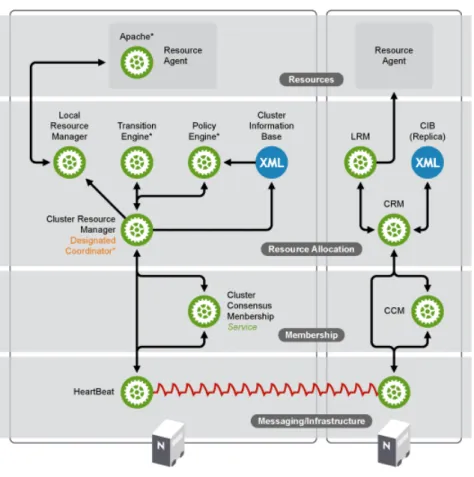
Heartbeat has a layered architecture. Figure 1.6, “Heartbeat Architecture” (page 9) illustrates the different layers and their associated components.
Figure 1.6 Heartbeat Architecture
Messaging and Infrastructure Layer
The primary or first layer is the messaging/infrastructure layer, also known as the Heartbeat layer. This layer contains components that send out the Heartbeat messages containing “I'm alive” signals, as well as other information. The Heartbeat program resides in the messaging/infrastructure layer.
Membership Layer
The second layer is the membership layer. The membership layer is responsible for calculating the largest fully connected set of cluster nodes and synchronizing this view
to all of its members. It performs this task based on the information it gets from the Heartbeat layer. The logic that takes care of this task is contained in the Cluster Con-sensus Membership service, which provides an organized cluster topology overview (node-wise) to cluster components that are the higher layers.
Resource Allocation Layer
The third layer is the resource allocation layer. This layer is the most complex, and consists of the following components:
Cluster Resource Manager
Every action taken in the resource allocation layer passes through the Cluster Re-source Manager. If any other components of the reRe-source allocation layer, or other components which are in a higher layer need to communicate, they do so through the local Cluster Resource Manager.
On every node, the Cluster Resource Manager maintains the Cluster Information Base, or CIB (see Cluster Information Base (page 10) below). One Cluster Resource Manager in the cluster is elected as the Designated Coordinator (DC), meaning that it has the master CIB. All other CIBs in the cluster are a replicas of the master CIB. Normal read and write operations on the CIB are serialized through the master CIB. The DC is the only entity in the cluster that can decide that a cluster-wide change needs to be performed, such as fencing a node or moving resources around. Cluster Information Base
The Cluster Information Base or CIB is an in-memory XML representation of the entire cluster configuration and status, including node membership, resources, constraints, etc. There is one master CIB in the cluster, maintained by the DC. All the other nodes contain a CIB replica. If an administrator wants to manipulate the cluster's behavior, he can use either thecibadmincommand line tool or the Heartbeat GUI tool.
NOTE: Usage of Heartbeat GUI Tool andcibadmin
The Heartbeat GUI tool can be used from any machine with a connection to the cluster. Thecibadmincommand must be used on a cluster node, and is not restricted to only the DC node.
Policy Engine (PE) and Transition Engine (TE)
Whenever the Designated Coordinator needs to make a cluster-wide change (react to a new CIB), the Policy Engine is used to calculate the next state of the cluster and the list of (resource) actions required to achieve it. The commands computed by the Policy Engine are then executed by the Transition Engine. The DC will send out messages to the relevant Cluster Resource Managers in the cluster, who then use their Local Resource Managers (see Local Resource Manager (LRM) (page 11) below) to perform the necessary resource manipulations. The PE/TE pair only runs on the DC node.
Local Resource Manager (LRM)
The Local Resource Manager calls the local Resource Agents (see Section “Resource Layer” (page 11) below) on behalf of the CRM. It can thus perform start / stop / monitor operations and report the result to the CRM. The LRM is the authoritative source for all resource related information on its local node.
Resource Layer
The fourth and highest layer is the Resource Layer. The Resource Layer includes one or more Resource Agents (RA). A Resource Agent is a program, usually a shell script, that has been written to start, stop, and monitor a certain kind of service (a resource). The most common Resource Agents are LSB init scripts. However, Heartbeat also supports the more flexible and powerful Open Clustering Framework Resource Agent API. The agents supplied with Heartbeat are written to OCF specifications. Resource Agents are called only by the Local Resource Manager. Third parties can include their own agents in a defined location in the file system and thus provide out-of-the-box cluster integration for their own software.
1.5.2 Process Flow
Many actions performed in the cluster will cause a cluster-wide change. These actions can include things like adding or removing a cluster resource or changing resource constraints. It is important to understand what happens in the cluster when you perform such an action.
For example, suppose you want to add a cluster IP address resource. To do this, you use either thecibadmincommand line tool or the Heartbeat GUI tool to modify the master CIB. It is not required to use thecibadmincommand or the GUI tool on the
Designated Coordinator. You can use either tool on any node in the cluster, and the local CIB will relay the requested changes to the Designated Coordinator. The Desig-nated Coordinator will then replicate the CIB change to all cluster nodes and will start the transition procedure.
With help of the Policy Engine and the Transition Engine, the Designated Coordinator obtains a series of steps that need to be performed in the cluster, possibly on several nodes. The Designated Coordinator sends commands out via the messaging/infrastructure layer which are received by the other Cluster Resource Managers.
If necessary, the other Cluster Resource Managers use their Local Resource Manager to perform resource modifications and report back to the Designated Coordinator about the result. Once the Transition Engine on the Designated Coordinator concludes that all necessary operations are successfully performed in the cluster, the cluster will go back to the idle state and wait for further events.
If any operation was not carried out as planned, the Policy Engine is invoked again with the new information recorded in the CIB.
When a service or a node dies, the same thing happens. The Designated Coordinator is informed by the Cluster Consensus Membership service (in case of a node death) or by a Local Resource Manager (in case of a failed monitor operation). The Designated Coordinator determines that actions need to be taken in order to come to a new cluster state. The new cluster state will be represented by a new CIB.
2
Installation and Setup
A Heartbeat cluster can be installed and configured using YaST. During the Heartbeat installation, you are prompted for information that is necessary for Heartbeat to function properly. This chapter contains information to help you install, set up, and configure a Heartbeat cluster. Learn about the hardware and software requirements and which preparations to take before installing Heartbeat. Find detailed information about the installation process and the configuration of a STONITH device.
NOTE: Installing Heartbeat Software Packages on Cluster Nodes
This Heartbeat installation program does not copy the Heartbeat software package to cluster nodes. Prior to running the installation program, the Heart-beat software package must be installed on all nodes that will be part of your cluster. This can be done during the SUSE Linux Enterprise Server 10 installation, or after.
The Heartbeat installation program lets you create a new cluster or add nodes to an existing cluster. To add new nodes to an existing cluster, you must run the installation program from a node that is already in the cluster, not on a node that you want to add to the cluster.
After installing Heartbeat, you need to create and configure cluster resources. You might also need to create file systems on a shared disk (Storage Area Network, SAN) if they do not already exist and, if necessary, configure those file systems as Heartbeat cluster resources.
Both cluster-aware (OCFS 2) and non-cluster-aware file systems can be configured with Heartbeat. See the Oracle Cluster File System 2 Administration Guide [http:// www.novell.com/documentation/sles10/sles_admin/data/ocfs2 .html] for more information.
2.1 Hardware Requirements
The following list specifies hardware requirements for a Heartbeat cluster. These re-quirements represent the minimum hardware configuration. Additional hardware might be necessary, depending on how you intend to use your Heartbeat cluster.
• A minimum of two Linux servers. The servers do not require identical hardware (memory, disk space, etc.).
• At least two communication media (Ethernet, etc.) that allow cluster nodes to communicate with each other. The communication media should support a data rate of 100 Mbit/s or higher.
• A STONITH device.
2.2 Software Requirements
Ensure that the following software requirements are met:
• SLES 10 with all available online updates installed on all nodes that will be part of the Heartbeat cluster.
• The Heartbeat software package including all available online updates installed to all nodes that will be part of the Heartbeat cluster.
2.3 Shared Disk System Requirements
A shared disk system (Storage Area Network, or SAN) is recommended for your cluster if you want data to be highly available. If a shared disk subsystem is used, ensure the following:
• The shared disk system is properly set up and functional according to the manufac-turer’s instructions.
• The disks contained in the shared disk system should be configured to use mirroring or RAID to add fault tolerance to the shared disk system. Hardware-based RAID is recommended. Software-based RAID1 is not supported for all configurations. • If you are using iSCSI for shared disk system access, ensure that you have properly
configured iSCSI initiators and targets.
2.4 Preparations
Prior to installation, execute the following preparatory steps:
• Configure hostname resolution by either setting up a DNS server or by editing the
/etc/hostsfile on each server in the cluster as described in Procedure 2.1, “Modifying/etc/hostswith YaST” (page 15). It is essential that members of the cluster are able to find each other by name. If the names are not available, inter-nal cluster communication will fail.
• Configure time synchronization by making Heartbeat nodes synchronize to a time server outside the cluster as described in Procedure 2.2, “Configuring the Heartbeat Servers for Time Synchronization” (page 16). The cluster nodes will use the time server as their time synchronization source.
Heartbeat does not require that time is synchronized for each of the nodes in the cluster, however, it is highly recommended if you ever plan to look at logfiles.
Procedure 2.1 Modifying /etc/hosts with YaST
1 On one SLES 10 server, open YaST, and in left column, select Network Services > Hostnames.
2 In the Host Configuration window, click Add and fill in the necessary information in the pop-up window for one other server in the cluster.
This information includes the IP address, hostname (for example node2.nov-ell.com), and host alias (for example node2) of the other server.
Use node names for host aliases. You can find node names by executinguname -nat a command prompt on each server.
3 Click OK, and then repeat Step 2 (page 15) to add the other nodes in the cluster to the/etc/hostsfile on this server.
4 Repeat Step 1 (page 15) through Step 3 (page 16) on each server in your Heartbeat cluster.
5 To check if hostname resolution is functioning properly, ping the node name (host alias) you specified in Step 2 (page 15) .
Procedure 2.2 Configuring the Heartbeat Servers for Time Synchronization
Time synchronization will not start unless the date and time on the cluster servers is already close. To manually set the date and time on cluster servers, use thedate
command at the command line of each cluster server to view, and if necessary change, the date and time for that server.
To configure the nodes in the cluster to use the time server as their time source proceed as follows:
1 On a cluster server, start YaST, click Network Services, then click NTP Client.
2 Choose to have the NTP daemon start during boot and then enter the IP address of the time server you configured.
3 Click Finish and reboot this server to ensure the service starts correctly.
4 Repeat Step 1 (page 16) through Step 3 (page 16) on the other non-time server nodes in the cluster.
5 Reboot all cluster nodes. After rebooting the nodes, time should be synchronized properly.
6 To check if time synchronization is functioning properly, run thentpq -p commandon each cluster node. Running thentpq -pcommand on a non-time server node will display the server that is being used as the time source.
2.5 Installing Heartbeat
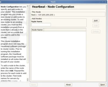
1 Start YaST and select Miscellaneous > High Availability or enteryast2 heartbeatto start the YaST Heartbeat module. It lets you create a new cluster or add new nodes to an existing cluster.
2 On the Node Configuration screen, add a node to the cluster by specifying the node name of the node you want to add, then click Add. Repeat this process for each node you want to add to the cluster, then click Next.
Figure 2.1 Node Configuration
You can find node names for servers by enteringuname -non each node.
The installation program will not let you add this node, because the node name of this server is already automatically added to the cluster.
If after adding a node to the cluster, you need to specify a different node name for that node, double-click the node you want to edit, change the node name, then click Edit.
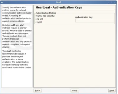
3 On the Authentication Keys screen, specify the authentication method the cluster will use for communication between cluster nodes, and if necessary an
Authenti-cation Key (password). Then click Next. Figure 2.2 Authentication Keys
Both the MD5 and SHA1 methods require a shared secret, which is used to protect and authenticate messages. The CRC method does not perform message authen-tication, and only protects against corruption, not against attacks.
The SHA1 method is recommended, because it provides the strongest authenti-cation scheme available. The authentiauthenti-cation key (password) you specify will be used on all nodes in the cluster.
When running this installation program on the other cluster nodes, you should choose the same authentication method for all nodes.
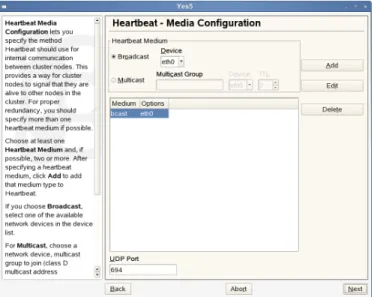
4 On the Media Configuration screen, specify the method Heartbeat will use for internal communication between cluster nodes. This configuration is written to
/etc/ha.d/ha.cf.
Figure 2.3 Media Configuration
This provides a way for cluster nodes to signal that they are alive to other nodes in the cluster. For proper redundancy, you should specify at least two Heartbeat media if possible. Choose at least one Heartbeat medium, and if possible, more than one:
• If you choose Broadcast, select one of the available network devices in the
Device list.
• For Multicast, choose a network Device, Multicast Group to join (class D multicast address 224.0.0.0 - 239.255.255.255) and the TTL value (1-255).
UDP Port sets the UDP port that is used for the broadcast media. Leave this set
to the default value (694) unless you are running multiple Heartbeat clusters on the same network segment, in which case you need to run each cluster on a dif-ferent port number.
NOTE: UDP Port Settings
Note that the UDP port setting only apply to broadcast media, not to the other media you may use. When editing UDP ports manually in/etc/ ha.d/ha.cf, theudpportentry must precede thebcastentry it belongs to, otherwise Heartbeat will ignore the port setting.
After specifying a Heartbeat medium, click Add to add that medium type to Heartbeat and proceed with Next.
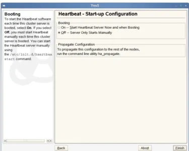
5 On the Start-up Configuration screen, choose whether you want to start the Heartbeat software on this cluster server each time it is booted.
Figure 2.4 Startup Configuration
If you select Off, you must start Heartbeat manually each time this cluster server is booted. You can start the Heartbeat server manually using thercheartbeat startcommand.
To start the Heartbeat server immediately, select On - Start Heartbeat Server
Now and when Booting.
To start Heartbeat on the other servers in the cluster when they are booted, enter
chkconfig heartbeat onat the server console of each of those servers.
You can also enterchkconfig heartbeat offat the server console to
have Heartbeat not start automatically when the server is rebooted.
6 To configure Heartbeat on the other nodes in the cluster run
/usr/lib/heartbeat/ha_propagateon the heartbeat node you just configured. On 64-bit systems, the commandha_propagateis located below
/usr/lib64/heartbeat/.
This will copy the Heartbeat configuration to the other nodes in the cluster. You will be prompted to enter the root user password for each cluster node.
7 Runrcheartbeat startto start heartbeat on each of the nodes where the configuration has been copied.
2.6 Configuring STONITH
STONITH is the service used by Heartbeat to protect shared data. Heartbeat is capable of controlling a number of network power switches, and can prevent a potentially faulty node from corrupting shared data by using STONITH to cut the power to that node. With the STONITH service configured properly, Heartbeat does the following if a node fails:
• Notices that the node is not sending “I'm alive” packets out to the cluster. • Sends out pre-stop notifications to the other cluster nodes.
These notifications include messages that the failed node will be powered off. • Instructs the STONITH service to power off the failed node.
• Sends post-stop notifications to other cluster nodes after successfully powering off the failed node.
These notifications include messages that the failed node will be powered off.
For Heartbeat, STONITH must be configured as a cluster resource. After reviewing Chapter 4, Configuring and Managing Cluster Resources (page 29), continue with Procedure 2.3, “Configuring STONITH as a Cluster Resource” (page 22).
Procedure 2.3 Configuring STONITH as a Cluster Resource
1 Start the HA Management Client and log in to the cluster as described in Section 4.1, “Graphical HA Management Client” (page 29).
2 To generally enable the use of STONITH, select the linux-ha entry in the left pane and click the Configurations tab on the right.
3 Activate the STONITH Enabled check box.
4 From the menu, select Resources > Add New Item or click the+button.
5 Choose Native as the item type.
6 Specify the Resource ID (name) for the STONITH resource.
7 In the Type section of the window, scroll down and select the type of STONITH device that corresponds to your network power switch.
8 (Conditional) After selecting a STONITH resource type, a line for that resource type might be added to the Parameters section of the screen. If a line is added, click the line once and then click the line again under the Value heading to open a field where you can add the needed value.
Some STONITH options require you to add parameter values in the parameters section of the page. For example, you may be required to add host names (server names) for each cluster node in your cluster. You can find the hostname for each server using theuname -ncommand on the server. You can add multiple hostnames in the provided field using a comma or a space to separate the names.
9 Select the Clone check box. This allows the resource to simultaneously run on multiple cluster nodes.
10 In the clone_node_max field, enter the number of instances of STONITH that will run on a given node. This value should normally be set to1.
11 In the clone_max field, enter the number of nodes in the cluster that will run the STONITH service. Be mindful of the number of concurrent connections your STONITH device supports.
12 Enter the Clone or Master/Slave ID.
13 Click Add to add the STONITH resource to the cluster. It now appears below the Resources entry in the left pane.
14 Select the resource in the left pane and click Resource > Start to start the STONITH resource.
After creating the STONITH resource, you must create location constraints for it. Lo-cation constraints determine which nodes STONITH can run on in the cluster. See
Constraints [http://www.linux-ha.org/ClusterInformationBase/
SimpleExamples] on the High Availability Linux Web site.
Starting the STONITH resource will cause it to start on the nodes that have been spec-ified with its resource location constraints.
3
Setting Up a Simple Resource
Once your cluster is installed and set up as described in Chapter 2, Installation and
Setup (page 13), you can start adding resources to your configuration. Configure
re-sources either with the Heartbeat GUI or manually by using the command line tools. In the following, find an example of how to configure an IP address as a resource either manually or with the Heartbeat GUI.
3.1 Configuring a Resource with the
Heartbeat GUI
Creating a sample cluster resource and migrating it to another server can help you test to ensure your Heartbeat cluster is functioning properly. A simple resource to configure and migrate is an IP address.
Procedure 3.1 Creating an IP Address Cluster Resource
1 Start the HA Management Client and log in to the cluster as described in Section 4.1, “Graphical HA Management Client” (page 29).
2 Click Resources, then click Add New Item, or click the+button.
3 Choose Native as the resource item type, then click OK.
4 Enter a Resource ID (name) for the IP address resource. For example,
ipaddress1.
5 In the Type section of the page, scroll down the list and selectIPaddr (OCF Resource Agent)as the resource type.
6 In the Parameters section of the page, find the line that was added for the IP address resource, click the line once, then click the line again under the Value heading to open a text field.
7 Add the IP address for the IP address cluster resource.
8 Click the Add Parameter button and from the drop-down list, specifynicas
Name andeth0as Value, then click OK.
The name and value are dependent on your hardware configuration and what you chose for the media configuration during the Heartbeat installation.
9 Click the Add button at the bottom of the page to add the resource to the cluster.
10 Select the resource in the left pane of the main window, then click Resources > Start to start the new resource on the cluster.
Procedure 3.2 Migrating Resources to Another Node
To migrate the newly created resource to another node in the cluster, you can use either the HA Management Client or the command line.
1 It the command line, use the following command:
crm_resource -M -r resource_name -H hostname
For example, to migrate a resource namedipaddress1to a cluster node named
node2, you would need to enter:
crm_resource -M -r ipaddress1 -H node2
2 To use the HA Management Client for migration, select the resource you want to migrate in the left pane of the main window and select Resources > Migrate
Resource.
3 In the new window, selectipaddress1as Resource to migrate and select
node1from the To Node drop-down list.
3.2 Manual Configuration of a
Resource
Resources are any type of service that a computer provides. Resources are known to Heartbeat when they may be controlled by RAs (Resource Agents), which are LSB scripts, OCF scripts, or legacy Heartbeat 1 resources. All resources are configured in the CIB (Cluster Information Base) in theresourcessection. For an overview of available resources, look at Appendix A, HB OCF Agents (page 109).
To add a resource to the current configuration, first write an XML file with the specific date for this resource. For example, to add the IP address10.10.0.1to your cluster, use the following example:
<primitive id="ip_1"❶
class="ocf" ❷
type="IPaddr" ❷
provider="heartbeat" ❷ > <instance_attributes>
<attributes>❸
<nvpair name="ip" value="10.10.0.1"❹/> </attributes>
</instance_attributes> </primitive>
❶ The value of theidattribute of theprimitivetag may be chosen freely. Like all IDs in XML, it must be unique and should follow a system. For example,ip_1
may be read as the firstipprimitive.
❷ The three attributesclass,type, andproviderdetermine the exact script that is used for this primitive. In this example, the script is at/usr/lib/ocf/ resource.d/heartbeat/IPaddr.
❸ All the attributes for a resource agent are entered in a list ofnvpairtags. This should not be confused with the XML attributes that are added, for example, to theprimitivetag.
❹ In this example, the RA attributeipis set to10.10.0.1. For theIPaddrRA, this RA attribute is mandatory, as can be seen in Appendix A, HB OCF Agents (page 109).
NOTE
When configuring a resource with Heartbeat, the same resource should not be initialized by init. Heartbeat should be responsible for all service start or stop actions.
To add thisIPaddrconfiguration to the cluster, first save the configuration to a file namedip_1.xml. Add this file to the cluster configuration with the command:
cibadmin -o resources -C -x ip_1.xml
If the configuration was successful, a new resource appears incrm_monthat is started on a random node of your cluster.
4
Configuring and Managing
Cluster Resources
Cluster resources must be created for every resource or application you run on servers in your cluster. Cluster resources can include Web sites, e-mail servers, databases, file systems, virtual machines, and any other server-based applications or services you want to make available to users at all times.
You can either use the graphical HA Management Client utility, or thecibadmin
command line utility to create resources.
This chapter introduces the graphical HA Management Client and then covers several topics you need when configuring a cluster: creating resources, configuring constraints, specifying failover nodes and failback nodes, configuring resource monitoring, starting or removing resources, configuring resource groups or clone resources, and migrating resources manually.
4.1 Graphical HA Management Client
When starting the Heartbeat GUI, you need to connect to a cluster.
NOTE: Password for thehaclusterUser
The Heartbeat installation creates a linux user namedhacluster. Prior to using the HA Management Client, you must set the password for the
haclusteruser. To do this, enterpasswd haclusterat the command line and enter a password for thehaclusteruser.
Do this on every node where you will run the HA Management Client utility.
To start the HA Management Client, enterhb_guiat the command line of a Linux server or workstation. Log in to the cluster by selecting Connection > Login. You are prompted for a username and password.
If you are running the HA Management Client on a Heartbeat cluster server, the server and username fields should already be filled in. If not, specify the server IP address of a cluster server andhaclusteras the username.
After being connected, your main window shows the cluster components, resources and constraints:
Depending on which entry you select in the left pane, several tabs appear in the right pane of the main window. For example, if you select the topmost entry, linux-ha, you can access three tabs on the right in the main window, allowing you to view general
Information on the cluster or to change certain options and aspects on the Configurations
and Advanced tabs.
In the following, find some examples how to create and manage cluster resources with the HA Management Client.
4.2 Creating Cluster Resources
To add a cluster resource:
1 Start the HA Management Client and log in to the cluster as described in Sec-tion 4.1, “Graphical HA Management Client” (page 29).
2 Select Resources > Add New Item, or click the + button.
3 Choose the resource item type you want to create, then click OK. The possible options are:
• Native • Group
• Location (Constraint) • Order (Constraint) • Colocation (Constraint)
All but the Native and Group resource item types are constraints. You must have a resource or group created in order to create a constraint and add that constraint to a resource.
4 Enter the Resource ID (name) and if desired, choose a group to add the resource to.
5 Select the resource Type from the list. To display a brief description of that re-source type, double-click any of the rere-source types in the list.
6 Conditional: After selecting a resource type, a line for that resource type might be added to the Parameters section of the screen. If a line is added, click the line once and then click the line again under the Value heading to open a field where you can add the needed value.
6a Add the needed value for the resource.
For example, if you selected an IP address as the resource type above, enter the IP address for the resource.
6b Click Add Parameter, specify the parameter Name and Value, then click OK.
7 Click Add at the bottom of the screen to add the resource to the cluster.
4.3 Configuring Resource Constraints
Resource constraints let you specify which cluster nodes resources will run on, what order resources will load, and what other resources a specific resource is dependent on. For information on configuring resource constraints, see Constraints [http:// linux-ha.org/ClusterInformationBase/SimpleExamples] on the High Availability Linux Web site.
4.4 Specifying Resource Failover
Nodes
Cluster resources will automatically fail over to another node in the cluster in the event of a software or hardware failure. If you have more than two nodes in your cluster, the node a particular resource fails over to is chosen by the Heartbeat software. If you want to choose which node a resource will fail over to, you must configure a location con-straint for that resource.
1 Start the HA Management Client and log in to the cluster as described in Section 4.1, “Graphical HA Management Client” (page 29).
2 Select the desired resource or group, select Resources > Add New Item, or click the + button.
3 Choose Location as the resource item type, then click OK.
4 Specify the ID of the resource constraint. The resource name for the resource you selected should already be displayed in the Resource field.
5 Click OK to add the constraint. The score will automatically be set to0by default to avoid unwanted effects caused by an incomplete rule.
Score indicates the value you are assigning to this resource constraint. Con-straints with higher scores are applied before those with lower scores. By creating additional location constraints with different scores for a given re-source, you can specify an order for the nodes that a resource will fail over to.
6 If you need to modify the score, select the added constraint in the left pane of the main window and enter a new Score value in the Attributes section in the right pane.
7 On the left side of the page, select the resource constraint you just created and click Add Expression.
8 Select #uname as the Attribute, eq as the Operation, and the server name of the failover node as the Value.
9 Click OK, then click Apply to save your changes.
10 Conditional: If you want to specify additional failover nodes for a resource, create additional location constraints by performing Step 1 (page 33) through Step 9 (page 34) for each constraint.
4.5 Specifying Resource Failback
Nodes (Resource Stickiness)
A resource will automatically fail back to its original node when that node is back online and in the cluster. If you want to prevent a resource from failing back to the node it was running on prior to a failover, or if you want to specify a different node for the resource to fail back to, you must change its resource stickiness value. You can specify resource stickiness when you are creating a resource, or after.
To specify resource stickiness for a resource after it has been created:
1 Start the HA Management Client and log in to the cluster as described in Sec-tion 4.1, “Graphical HA Management Client” (page 29).
2 Select the desired resource or group, click the Attributes tab, then click Add
At-tribute.
3 In the Name field, typeresource_stickiness.
4 In the Value field, specify a value between-100,000and100,000. Consider the following when specifying a resource stickiness value:
Value is0:
This is the default. The resource will be placed optimally in the system. This may mean that it is moved when a “better” or less loaded node becomes available. This option is almost equivalent to automatic failback, except that the resource may be moved to a node that is not the one it was previously active on.
Value is greater than0:
The resource will prefer to remain in its current location, but may be moved if a more suitable node is available. Higher values indicate a stronger preference for a resource to stay where it is.
Value is less than0:
The resource prefers to move away from its current location. Higher absolute values indicate a stronger preference for a resource to be moved.
Value is100,000:
The resource will always remain in its current location unless forced off because the node is no longer eligible to run the resource (node shutdown, node standby, or configuration change). This option is almost equivalent to completely disabling automatic failback, except that the resource may be moved to other nodes than the one it was previously active on.
Value is-100,000:
The resource will always move away from its current location. See also thecrm_failcountcommand: crm_failcount(8) (page 81).
4.6 Configuring Resource Monitoring
Although Heartbeat can detect a node failure, it also has the ability to detect when an individual resource on a node has failed. If you want Heartbeat to ensure that a resource is running, you must configure resource monitoring for that resource. Resource moni-toring consists of specifying a timeout and/or start delay value, and an interval. The interval tells Heartbeat how often it should check the resource status.
To configure resource monitoring:
1 Start the HA Management Client and log in to the cluster as described in Sec-tion 4.1, “Graphical HA Management Client” (page 29).
2 Select the resource, click the Operations tab, then click Add Operation.
3 Select Monitor as the operation name.
4 Add the desired values in the Interval, Timeout, and Start Delay fields, and a description if desired.
5 Click OK, then click Apply to start the monitoring operation.
If you do not configure resource monitoring, resource failures after a successful start will not be communicated, and the cluster will always show the resource as healthy. If the resource monitor detects a failure, the following actions will take place:
• Log file messages will be generated
• The failure will be reflected in the hb_gui and crm_mon tools, and in the CIB status section
• The cluster will initiate noticeable recovery actions which may include stopping the resource to repair the failed state and restarting the resource locally or on another node. The resource also may not be restarted at all, depending on the configuration and state of the cluster.
4.7 Starting a New Cluster Resource
Some cluster resources do not start automatically after being created. To start a new cluster resource after creating it, in the HA Management Client, select the resource in the left pane, then click Resource > Start.
4.8 Removing a Cluster Resource
You can remove a cluster resource using the HA Management Client. To do this, select the resource in the left pane, and click Resource > Delete.
4.9 Configuring a Heartbeat Cluster
Resource Group
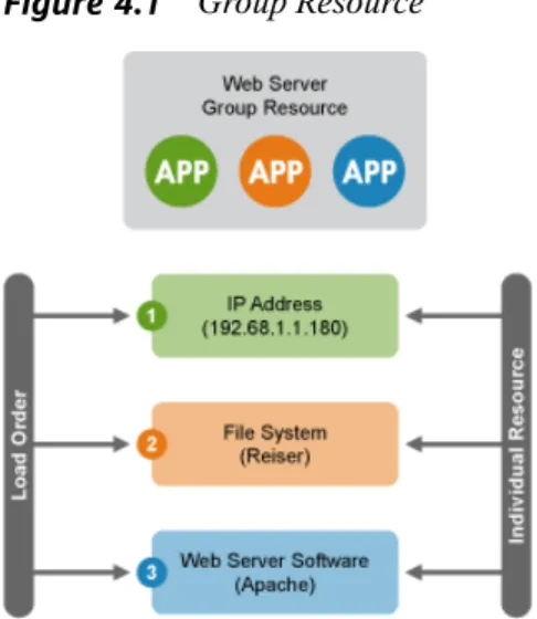
Some cluster resources are dependent on other components or resources, and require that each component or resource are started in a specific order and run together on the same server. An example of this is a Web server that requires an IP address and a file system. In this case each component is a separate cluster resource that is combined into a cluster resource group. The resource group would then run on a server or servers, and in case of a software or hardware malfunction, fail over to another server in the cluster the same as an individual cluster resource.
Figure 4.1 Group Resource
To configure a resource group using the above example:
1 Start the HA Management Client and log in to the cluster as described in Section 4.1, “Graphical HA Management Client” (page 29).
2 Select Resources > Add New Item, or click the + button.
3 Choose Group as the resource item type, then click OK.
4 Specify a Group name (ID), leave the default ofTruefor both the Ordered and Collocated fields, then click OK.
The Ordered value specifies, if the resources in the group will load in order you specified. The Collocated value specifies whether the resources in the group will run on the same server.
5 Specify a resource name (ID) for the IP address resource portion of the group.
6 In the Type section of the page, scroll down the list and select IPaddr2 (OCF
Resource Agent) as the resource type.
7 In the Parameters section of the page, find the line that was added for the IP address resource, click the line once, then click the line again under the Value heading to open a text field.
8 Add the IP address for the IP address cluster resource.
9 Click the Add Parameter button, select nic as the name and entereth0as the value, then click OK.
The name and value are dependent on your hardware configuration and what you chose in Step 3 (page 31).
10 Click the Add button at the bottom of the page to add the resource to the group.
4.9.1 Adding a File System to the Resource
Group
1 Using the HA Management Client, select Resources, and then select Add New
Item, or click the + button.
2 Choose Native as the resource item type, then click OK.
3 Specify a resource name (ID) for the file system resource, and in the Belong to
Group field, select the group you created above.
4 In the Type section of the page, scroll down the list and select Filesystem as the resource type.
5 In the Parameters section of the page, find the line that was added for the file system resource, click the line once, then click the line again under the Value heading to open a text field.
6 Add the name of the file system. For example,Reiser.
7 Click the Add Parameter button and select Device as the name. For the value, specify the device where the file system is located, then click OK.
The name and value are dependent on your hardware configuration. For example, you could specify/dev/sdcas the value if the file system is on that device.
4.9.2 Adding the Web Server to the
Resource Group
1 Using the HA Management Client, select Resources, and then select Add New
Item, or click the + button.
2 Choose Native as the resource item type, then click OK.
3 Specify a resource name (ID) for the Web Server resource, and in the Belong to
group field, select the group you created above.
4 In the Type section of the page, scroll down the list and select Apache as the re-source type.
5 In the Parameters section of the page, find the line that was added for the Apache Web server resource, accept or change the path to the Apache Web server, then click OK.
NOTE
If you want to enable resource monitoring for a group resource, you must configure monitoring separately for each resource in the group that you want monitored.
4.10 Configuring a Heartbeat Clone
Resource
You may want certain resources to run simultaneously on multiple nodes in your cluster. To do this you must configure a resource as a clone. Examples of resources that might be configured as clones include STONITH and cluster file systems like OCFS2. You can clone any resource provided it is supported by the resource’s ResourceAgent. Clone resources may even be configured differently depending on which nodes they are hosted.
There are three types of resource clones:
• Anonymous Clones: These are the simplest type of clones. They behave iden-tically anywhere they are running.
• Globally Unique Clones: These resources are distinct entities. An instance of the clone running on one node is not equivalent to another instance on another node; nor would any two instances on the same node be equivalent.
• Stateful Clones: Active instances of these resources are divided into two states, active and passive. These are also sometimes referred to as primary and secondary, or master and slave. Stateful clones can be either anonymous or globally unique.
1 To configure a resource as a clone, follow Step 1 (page 31) through Step 6 (page 32) in Section 4.2, “Creating Cluster Resources” (page 31).
2 Select the Clone check box. This will allow the resource to simultaneously run on multiple cluster nodes.
3 In the clone_node_max field, enter the number of instances of the resource that will run on a given node.
4 In the clone_max field, enter the number of nodes in the cluster that will run the resource.
5 Click Add to add the clone resource to the cluster.
6 Select the resource in the left pane and click Resource > Start to start the resource. Starting the clone resource will cause it to start on the nodes that have been specified with its resource location constraints.
After creating the resource, you must create location constraints for the resource. The location constraints determine which nodes the resource can run on. See
Constraints [http://www.linux-ha.org/
ClusterInformationBase/SimpleExamples] on the High Availability Linux Web site.
4.11 Migrating a Cluster Resource
Although resources are configured to automatically fail over (or migrate) to other nodes in the cluster in the even of a hardware or software failure, you can also manually migrate a resource to another node in the cluster using either the HA Management Client or the command line.
1 At the command line, use the following command:
crm_resource -M -r resource_name -H hostname -f
For example, to migrate a resource namedipaddress1to a cluster node named
node2, you would need to enter:
crm_resource -M -r ipaddress1 -H node2 -f
To get a list of parameters and switches that can be used with the
crm_resourcecommand, entercrm_resourcewithout any options.
2 To use the HA Management Client for migration, start the HA Management Client and log in to the cluster as described in Section 4.1, “Graphical HA Man-agement Client” (page 29).
3 Select the resource you want to migrate in the left pane of the main window and select Resources > Migrate Resource.
4 In the new window, selectipaddress1as Resource to migrate and select
node1from the To Node drop-down list.
5
Manual Configuration of a
Cluster
Manual configuration of a Heartbeat cluster is often the most effective way of creating a reliable cluster that meets specific needs. Because of the extensive configurability of Heartbeat and the range of needs it can meet, it is not possible to document every pos-sible scenario. To introduce several concepts of the Heartbeat configuration and demonstrate basic procedures, consider a real world example of an NFS file server. The goal is to create an NFS server that can be built with very low-cost parts and is as re-dundant as possible. For this, set up the following cluster:
• Two machines that have redundant hardware
• Data is mirrored on the disks of those machines with drbd • Only one machine at a time accesses and exports the data
• Assign a special IP address to the computer for exporting the file system
Before starting with the cluster configuration, set up two nodes as described in Chapter 2,
Installation and Setup (page 13). In addition to the system installation, both should
have a data partition of the same size to setup drbd.
The configuration splits into two main parts. First, all the resources must be configured. After this, create a set ofconstraintsthat define the starting rules for those re-sources.
All the configuration data is written in XML. For convenience, the example relies on snippets that may be loaded into the cluster configuration individually.
5.1 Configuration Basics
The cluster is divided into two main sections, configuration and status. The status section contains the history of each resource on each node and based on this data, the cluster can construct the complete current state of the cluster. The authoritative source for the status section is the local resource manager (lrmd) process on each cluster node. The cluster will occasionally repopulate the entire section. For this reason it is never written to disk and administrators are advised against modifying it in any way.
The configuration section contains the more traditional information like cluster options, lists of resources and indications of where they should be placed. It is the primary focus of this document and is divided into four parts:
• Configuration options (called crm_config) • Nodes
• Resources
• Resource relationships (called constraints)
Example 5.1 Structure of an Empty Configuration
<cib generated="true" admin_epoch="0" epoch="0" num_updates="0" have_quorum="false"> <configuration> <crm_config/> <nodes/> <resources/> <constraints/> </configuration> <status/> </cib>
5.1.1 The Current State of the Cluster
Before you start to configure a cluster, it is worth explaining how to view the finished product. For this purpose use thecrm_monutility that will display the current state of an active cluster. It can show the cluster status by node or by resource and can be used in either single-shot or dynamically-updating mode. Using this tool, you can examine the state of the cluster for irregularities and see how it responds when you cause or simulate failures.
Details on all the available options can be obtained using thecrm_mon --help
command.
5.1.2 Updating the Configuration
There is a basic warning for updating the cluster configuration:
WARNING: Rules For Updating the Configuration
Never edit thecib.xmlfile manually, otherwise the cluster will refuse to use the configuration. Instead, always use thecibadmintool to change your configuration.
To modify your cluster configuration, use thecibadmincommand which talks to a running cluster. Withcibadmin, you can query, add, remove, update or replace any part of the configuration. All changes take effect immediately and there is no need to perform a reload-like operation.
The simplest way of usingcibadminis a three-step procedure:
1 Save the current configuration to a temporary file:
cibadmin --cib_query > /tmp/tmp.xml
2 Edit the temporary file with your favorite text or XML editor.
Some of the better XML editors are able to use the DTD (document type defini-tion) to make sure that any changes you make are valid. The DTD describing the
configuration can be found in/usr/lib/heartbeat/crm.dtdon your
systems.
3 Upload the revised configuration:
cibadmin --cib_replace --xml-file /tmp/tmp.xml
If you only want to modify theresourcessection, do the following to avoid modi-fying any other part of the configuration:
cibadmin --cib_query --obj_type resources > /tmp/tmp.xml vi /tmp/tmp.xml
cibadmin --cib_replace --obj_type resources --xml-file /tmp/tmp.xml
5.1.3 Quickly Deleting Part of the
Configuration
Sometimes it is necessary to delete an object quickly. This can be done in three easy steps:
1 Identify the object you wish to delete, for example:
cibadmin -Q | grep stonith
<nvpair id="cib-bootstrap-options-stonith-action" name="stonith-action" value="reboot"/>
<nvpair id="cib-bootstrap-options-stonith-enabled" name="stonith-enabled" value="1"/>
<primitive id="child_DoFencing" class="stonith" type="external/vmware"> <lrm_resource id="child_DoFencing:0" type="external/vmware" class="stonith"> <lrm_resource id="child_DoFencing:0" type="external/vmware" class="stonith"> <lrm_resource id="child_DoFencing:1" type="external/vmware" class="stonith"> <lrm_resource id="child_DoFencing:0" type="external/vmware" class="stonith"> <lrm_resource id="child_DoFencing:2" type="external/vmware" class="stonith"> <lrm_resource id="child_DoFencing:0" type="external/vmware" class="stonith"> <lrm_resource id="child_DoFencing:3" type="external/vmware" class="stonith"> 2 Identify the resource’s tag name and id (in this caseprimitiveand
child_DoFencing.
3 Executecibadmin:
cibadmin --cib_delete --crm_xml ‘<primitive id=”child_DoFencing”/>’
5.1.4 Updating the Configuration Without
Using XML
Some common tasks can also be performed with one of the higher level tools that avoid the need to read or edit XML. Run the following command to enableSTONITH, for example:
crm_attribute --attr-name stonith-enabled --attr-value true
Or to see ifsomenodeis allowed to run resources, there is:
crm_standby --get-value --node-uname somenode