Sharif University of Technology
Scientia IranicaTransactions A: Civil Engineering www.scientiairanica.com
Numerical simulation of the ow under sluice gates by
SPH model
M. Khanpour, A.R. Zarrati
and M. Kolahdoozan
Department of Civil and Environmental Engineering, Amirkabir University of Technology, Tehran, P.O. Box 15914, Iran. Received 3 September 2012; received in revised form 26 October 2013; accepted 26 November 2013
KEYWORDS Sluice gate; SPH;
Discharge-scale relationship;
Discharge coecient; Vena contracta; Numerical model.
Abstract. Sluice gates are widely used for ow control in open channels. Flow under a gate is complicated with a rapidly varying free surface and dynamic pressure distribution. Due to this complexity, most of the studies to date are based on physical models. In the present study the ow under sluice gates on a at bed is modeled numerically. Owing to the capabilities of SPH model, in simulating rapidly varied free surface ows, this Lagrangian method was applied in the present study. The SPH model was further developed by introducing IXSPH and an innovative method was proposed to simulate the constant inow discharge. The present model results for free surface prole, as well as velocity and pressure eld indicated good agreement with experimental and existing Eulerian numerical results. In the present work, the contraction and discharge coecients were also captured for dierent opening ratios and gate inclinations. This study shows the ability of the developed SPH model as a useful tool in designing hydraulic structures.
© 2014 Sharif University of Technology. All rights reserved.
1. Introduction
Sluice gates are widely employed for discharge and ow depth control in irrigation channels, large sewers, and in hydraulic structures. Due to the practical importance of the sluice gates, the prediction of scale discharge relationship and ow characteristics, such as free surface location and pressure distribution on the gate, is one of the classical problems in hydraulic engineering [1]. As a result, ows under the gates have been investigated physically and mathematically by many researchers [1-6].
A survey of the literature shows that most of the numerical simulation for modeling ow under the gates is conducted by Eulerian models. The ow under the gate is classied as rapidly varied ow in which the cur-vature of the ow is considerable and non-hydrostatic pressure is developed. Prediction of free surface in
*. Corresponding author. Tel.: +98 21 64543002; Fax: +98 21 66414213
E-mail address: [email protected] (A.R. Zarrati)
such a rapidly varied ow, which its location is not known in advance, is one of the challenging problems in mesh-based Eulerian numerical models. The marker-and-cell and volume of uid methods are two of the most exible and powerful models for simulating free surface ow in which the N-S equations are solved on a xed Eulerian grid. Despite of successful application of these methods for treating free surface ows, they are dicult in programming. In addition, some errors such as numerical diusion and mesh deformation could be raised due to solving N-S equations on a xed Eulerian grid especially when the deformation of free surface is very large such as in a vena contracta [7].
More recently, the Smoothed Particle Hydrody-namics (SPH) method has been adapted from astro-physics into a number of engineering problems in uid mechanics including free surface ows [8-10]. SPH oers a variety of advantages for uid modeling, par-ticularly those with a free surface and non-hydrostatics pressure distribution. SPH method is mesh free in which moving uid particles are the equivalents of mesh points and the free surface requires no special
treatment. The SPH methodology is applied to dif-ferent engineering problems, such as wave generation by submarine landslides [11], sloshing problems [12], wave propagation and ooding [13,14], wave interaction with structures and solids [15,16,17], and hydraulic jumps [18]. By considering these applications, it seems that SPH is very capable method in modeling rapidly varied free surface ows, such as ow under a gate.
On the other hand, dealing with solid boundary, as well as inlet and outlet boundaries, is complicated in SPH methods. Researchers have recommended dierent approaches to treat the solid boundary such as boundary particles [8] and ghost particles [19]. Dif-ferent modications are also suggested to improve the stability of classical SPH version such as XSPH method presented by Monaghan [8]. In the present paper, the SPH method is employed to simulate the ow under the sluice gates. Various improvements suggested in the literature for SPH techniques were utilized and their performances were compared. New developments were also suggested to improve the stability and results of the model, and a new approach was also introduced for treating the inow boundary.
2. Mathematical model 2.1. Governing equation
The main features of the SPH method is based on integral interpolates of any function A(r0) which is
described by: A(r) =
Z
A(r0)W (r r0; h)dr0; (1)
where h is called the smoothing length, and W (r r0; h)
is the weighting function or kernel. The parameter h or the inuence domain controls the size of the area around the particle a where contribution from the particles cannot be neglected. This approximation, in discrete notation, leads to the following approximation of the function at the particle a (interpolation point) as:
A(~r) =XN
i=1
mbAb
bWab; (2)
where the summation is over all the particles within the inuence domain of the particle a, and N is the number of neighbor particles in this domain. The mass and density of neighbor particles are denoted by mb
and b, respectively, and Wab = W ( ~ra ~rb; h) is the
weight function or kernel.
The performance of the SPH model is critically dependent on the choice of weighting functions. Ker-nels depend on the smoothing length, h, and the non-dimensional distance between particles. Throughout the present simulations, a two-dimensional cubic spline
kernel, which is computationally less expensive due to its lower order, was employed in the form [20]:
w(s; h) = D
8 > > < > > : 2
3 q2+12q3 0 q 1 1
6(2 q)3 1 q 2
0 q 2
9 > > = > >
;; (3) where q = r=h, and r is the distance between the particles a and b. In two dimensions, we have D =
15 7h2.
In the present model the summation density ap-proach was employed to approximate particle density. In this approach, SPH approximation (Eq. (2)) was applied to density itself. For a given particle, the density can be written in the form:
=XN
i=1
mbWab: (4)
In this technique, a quasi-incompressible equation of state is employed to produce pressure. Monaghan [8] applied the following equation of state to model the free surface:
P = B((
0)
1); (5)
where the constant = 7 is used in most circumstances, 0is reference density and the coecient B =c
2
with
a speed of sound c = 10p2gh in which h is the initial height of the water [8].
It is shown in the literature that viscous forces have little eect on ow condition under gates and the ow can be assumed inviscid [21,22]. The momentum equation for inviscid uid ows in Lagrangian form can be written as:
Dv
Dt = 1
@p
@x + F; (6)
where p is pressure, v is velocity, and F is the body force per unit mass. The Greek superscript is used to denote the coordinate direction.
The derivation of SPH approximation of momen-tum equation yields the symmetric Equation:
Dv a Dt = N X i=1
mb(P2a a + Pb 2 b) @Wab @x a + F
a: (7)
In the present model, to integrate the discrete SPH equations, the second order accurate Leap-Frog method was implemented. In this method, particle velocity and position are oset by a half time step when integrating the equation of motion. For simplicity, all particles are advanced with the same time step and the time step keeps unchanged in the model evolution.
Free surfaces are identied by particle densities. Since no particle exists in the outer region of the free surface, the particle density drops on the surface. Therefore, a particle is on the free surface if its density falls below the reference density.
The SPH model without a stabilization technique is not stable. In the present research, three dierent stabilization techniques were examined: (1) Articial viscosity; (2) An improved XSPH; and (3)- Shepard density ltering.
Articial viscosity is introduced in the pressure term of momentum equation. This Monaghan type articial viscosity is the most widely used so far in the SPH literature. In fact, articial viscosity imposes a repulsive force between two particles approaching each other, and in this way unphysical penetration is prevented. Articial viscosity, ab, is expressed as [8]:
ab=
( cabab
ab vabrab< 0
0 vabrrb> 0
)
; (8)
with ab=hvr2abrab ab+2 where:
rab= ra rb; vab= va vb;
cab= ca+ c2 b; ab=a+ 2 b:
In the above equations, 2 = 0:01h2 and is constant
which is typically set around 1.0 [23]. The result of the present work shows that = 0:1 yields more accurate result, while the stability of the model is also preserved. In the XSPH technique [8] the movement of particles is calculated by a corrected velocity which includes the contribution from neighboring particles and therefore makes the particles move in a velocity closer to the average velocity of the other neighboring particles. The corrected velocity for particle i in XSPH is obtained as:
Dxa
Dt = va "
N
X
i=1
mb
b vabWab; (9)
where " is a constant in the range of 0 " 1. Previous research works showed that the range of " = 0:5 would yield good results [8,24].
The XSPH technique was improved in the present work for a better stability of the model. In this improved version, which is called IXSPH, the corrected velocity is used in momentum equation as well as calculation of the new position of the particles.
In fact the inuence of applying this technique is similar to the repulsive force resulted in applying the articial viscosity technique and increases the stability of the standard SPH model. It should be mentioned that the accuracy of IXSPH is dependent on the
coecient ". By increasing this coecient the pressure oscillation decreases while the accuracy of the model is reduced similar to the coecient in articial viscosity relationship. In the present work, by applying the model to basic uid mechanics problems, the optimum value for " was found to be 0.02. By using this value, the stability of the model was satised while the accuracy of the model was also good [25]. In addition, the Shepard ltering density was also examined [26]. The result shows that applying this scheme did not aect the result considerably.
To check the convergence of the solution and com-pare the results of the numerical model for velocity and pressure proles with experimental data, a stationary grid was overlapped on the ow domain. The values of ow parameters, such as density, velocity and pressure, were saved in nodes of this grid in every 100 time steps. The node characteristics were calculated from particles in their neighborhood using the Kernel function. 2.2. Boundary condition
One of the problems in the SPH method is introducing the ow condition at inlet and outlet sections. Dierent approaches may be adopted to solve this problem.
One approach is that the particle leaving the computational domain from the outlet is not removed from the data bank while the entering particle from the inlet is added to the ow domain. This approach increases the cost of computation intensively. In another approach, the particle which leaves the ow domain is removed from the data bank and, instead, a particle is introduced to the domain with the same index of the removed particle. However in this strategy the data bank should be updated after some time steps and this updating also increases the computational time. Moreover, one number might be related to several particles, and as a result tracing particles becomes dicult.
Yoon et al. [27] modeled inow and outow by using hybrid methods. In the hybrid methods, the con-vection terms of the governing equation are solved on a mesh-based Eulerian system while the other terms are discretized and solved by a mesh-free particle method such as MPS. The nal results are a combination of these stages. This approach has some disadvantages such as those for mesh-based methods and numerical diusion [28]. Shakibaeinia and Jin [28] proposed an extra type of particle called `storage particles' in their model. Particles leaving and entering the solution domain are added to and subtracted from the storage particles. This approach however seems to be time consuming since the additional particles in the reservoir should be processed in every time step.
To reduce the time of computation, some re-searchers applied periodic condition to inlet and outlet sections. However the periodic condition imposes
restriction to ow simulation, as the inlet and outlet conditions eventually become the same like Poiseuille and Couette ow [29]. As a result, this method cannot be applied for modeling ow under the gates.
Federico et al. [30] performed a study of a 2D open-channel with a SPH model. In order to assign dierent upstream and downstream ow conditions, they introduced two new sets of particles (in/out-ow particles). In their work, several simulations of two hydraulic cases such as Poiseuille ow, uniform ow and hydraulic jump were carried out in which the inow depth were xed in time and were not inuenced by the uid particles. Additional coding is also necessary to specify in and out ow particles. It should be noticed that in simulating the ow under a gate, the upstream ow depth should be calculated by the model, which is a necessary boundary condition in all subcritical ows. In the present work, a new technique was used to solve this problem. In this technique, a vertical plate was assumed at the inlet section. The ow depth at the inlet was calculated by the model in each time step similar to subcritical condition in traditional Eulerian models. The velocity of the particles located on this imaginary plate was then adjusted to maintain the desired ow discharge at the inlet section. In this way, any discharge can be applied to the inlet, and the ow depth is adjusted by the solution.
To solve the problem, due to reduction of particles density near the solid boundaries, ghost particles, either xed or dynamic, can be employed. In the present work, (Figure 1) dynamic ghost particles were employed for the moving inlet boundary, and xed ghost particles were used for the gate and the channel invert to reduce the computation time.
3. Flow under the sluice gates
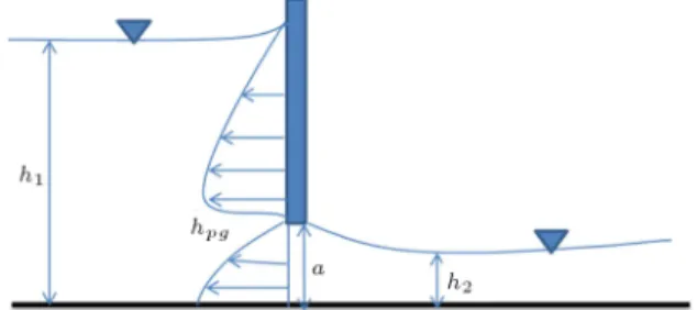
Flow past a sluice gate on a horizontal invert is illustrated in Figure 2. In this gure h1 represents
the ow depth, V1 is the ow velocity, h2 is the ow
depth at the vena contracta, V2is the downstream ow
velocity, a is the gate opening, and hpg denotes the
pressure head on the gate. The degree of contraction may be represented by the contraction coecient Cc,
dened as the ratio of the ow depth at the vena
contracta to the gate opening as:
Cc =ha2: (10)
The discharge through a sluice gate can be expressed in terms of the approach ow depth as [1,5]:
q = Cda
p
2gh1; (11)
where q is the discharge in unit width, Cd is the
discharge coecient, and g is the gravitational acceler-ation.
To determine discharges coecient researchers have proposed dierent equations which are developed from laboratory and prototype measurements, some of which are tabulated in Table 1 [31,32].
Flow characteristics under a gate are studied in details by Akoz et al. [2]. They conducted some experiments in a glass-walled, hydraulically smooth,
Figure 1. Schematic layout of the particles distribution around the gate.
Figure 2. Schematic of the ow domain past sluice gate. Table 1. Dierent formula for calculating discharge coecient [31,32].
Empirical formula for discharge coecient References Cd= 0:6468 0:1641
q
a
h1 Garbrecht (1977)
Cd= 0:62 0:15
q
a
h1 Noutsopoulos and Fanariotis (1978) Cd= 0:6exp( 0:3a=h1) Nago (1978)
Cd= 0:615
h
1 + 0:3a h1
i 1
Cozzo (1978) Cd= 0:13(ha1)0:714+ 0:22(ha1)0:595+ 0:388 Barahman et al. (2006)
horizontal laboratory channel containing a vertical smooth, sluice gate. In these tests, the gate opening was 1.2 cm and the discharge in unit width was 0.0105 m2/s. The velocity proles in this test were
measured using PIV. Kim [1] employed FLOW-3D to simulate the ow under the sluice gates. In this simulation, the free surface is calculated by VOF and the RNG model was used as turbulence closure. 4. Numerical simulation
To model the ow past a sluice gate with an opening a, at rst a stationary rectangular container with the length of 15a and the height of 5a was assumed. The uid, boundary and corresponding virtual particles were distributed with the same spacing in this rect-angular container. At rst, this container was assumed stationary and the model was run till hydrostatic pressure distribution was established in the container (Figure 3). In this case, four stabilization techniques were studied. At rst, articial viscosity was applied for the stabilization. Figure 4(a) shows the eect of this technique in damping the pressure oscillation. The IXSPH (improved XSPH) scheme was studied next (Figure 4(b)). As can be seen, by applying this scheme, the pressure oscillation was damped gradually and the model was stable. The comparison between traditional XSPH (without articial viscosity) and IXSPH is shown in Figure 4(c). As it can be seen IXSPH is more eective in damping pressure oscillation in the model. The result in Figure 4(d) shows that even applying the IXSPH together with Shepard density ltering did not improve damping of the pressure oscillation of the model. This result shows that by using IXSPH alone and without need to articial
Figure 3. Hydrostatic pressure in stationary rectangular container.
viscosity or Shepard density ltering, the stability of the model is provided.
After this stage, the right wall particles and corresponding virtual particles near the channel bed were removed to the extent that the opening was simulated and the left wall (inlet) was simultaneously moved towards the gate to establish the inlet ow condition (Figure 1). The velocity of particles on the inlet boundary and their position is calculated at each time step by:
v =yq; (12)
x = vt; (13)
where y is the ow depth at the inlet, t is the time, v is the horizontal velocity, and x is the x-coordinate of the inlet particles. The vertical velocity of the inlet particles was set to zero.
As inlet particles move toward the gate, the density and pressure of uid particles increase, and as a result, the uid particles accelerate due to the pressure gradient (Figure 1).
Two essential points should be considered here:
1. IXSPH technique should not be used for particles in the neighborhood of the solid stationary particles, otherwise their velocity decreases and acts as false friction in the model.
2. The particles of the channel invert are stationary and xed. As a result, the distance between the invert boundary particles and nearby moving uid particles changes in time. This movement causes pressure oscillation in the ow domain. To solve this problem, the pressure force from boundary particles to nearby uid particles in the x direction was set to zero, which is similar to slip condition at the solid wall. In the same way the pressure force from the gate particles in y direction were set to zero.
First experiences, after imposing the inlet bound-ary condition, revealed a surface wave due to sudden movement of the inlet particles. This surface wave destabilized the solution. To avoid this wave, the ow discharge was increased gradually in time to the desired value. It can be seen in Figure 5 that by this technique the height of the surface wave was reduced considerably.
5. Numerical results
The ow under the gate by the mentioned techniques such as the inlet boundary condition and the stabiliza-tion scheme was simulated. In Figure 6, the horizontal velocity contours and in Figure 7, pressure contours, of
Figure 4. The inuence of the stabilization techniques on the pressure oscillation in SPH model.
Figure 5. Wave surface due to the movement of the inlet boundary: a) Rapid movement; and b) gradual movement.
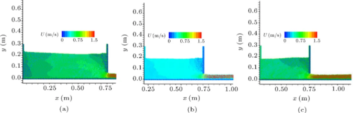
Figure 6. Horizontal velocity contours of uid particles around the gate for q = 0:0496 (m2/s): a) 0.6 s; b) 1.7 s; and c)
Figure 7. Pressure contours of uid particles around the gate for q = 0:0496 (m2/s): a) 0.6 s; b) 1.7 s; and c) 2.24 s.
Figure 8. Horizontal velocity around the gate in steady condition for dierent unit discharges for gate opening =5 cm: a) q = 0:0412 (m2/s); and b) q = 0:0634 (m2/s).
Table 2. Comparison of discharge coecient and upstream ow depth with ow 3D results [1].
Flow 3D result (Kim, 2007 [1])
The present model
Case q
(m2/s)
h1
(cm)
Cd
(cm)
h1
(cm) Cd
A 0.0306 7.48 0.506 7.6 0.501
B 0.0351 9.27 0.521 9.8 0.506
C 0.0412 11.89 0.54 12.5 0.537 D 0.0496 16.19 0.557 16.4 0.553
E 0.0634 24.66 0.577 25 0.572
uid particles around the gate for a constant discharge are shown in dierent times.
This simulation was continued till the steady state condition was reached and the ow depth upstream of the gate did not change considerably. Samples of the steady ow simulation under the gate calculated by the numerical model are shown in Figure 8.
The comparison of the numerical model results with Kim's numerical work [1] in Table 2 shows that the present model can predict the free surface and discharge coecient with good accuracy.
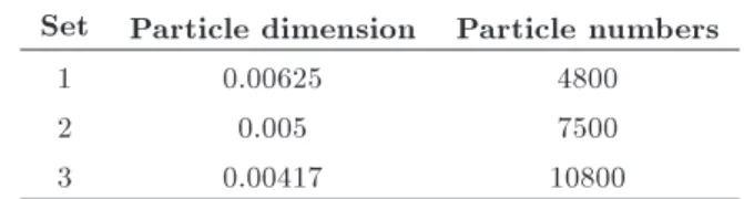
The inuence of particle size was investigated too. Case D in Table 2 was selected and the ow
Table 3. Three sets of particles size used in simulation of Case D.
Set Particle dimension Particle numbers
1 0.00625 4800
2 0.005 7500
3 0.00417 10800
was simulated with 3 dierent numbers of particles as shown in Table 3. It was concluded that increasing the number of particles more than twice did not aect the results considerably.
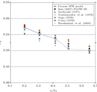
In the next stage, discharge coecient, calculated by the numerical model, was compared with empirical equations, presented in Table 1, and Kim [1] in Fig-ure 9. As can be seen from this gFig-ure, the SPH results are in the range of empirical, as well as the FLOW 3D predictions.
Water surface prole downstream of the gate is shown in Figure 10 in two of the tests more closely. As can be seen, the model is able to simulate the contraction of the ow downstream of the gate. The average contraction coecient calculated from dierent simulations was in the range of 0:61 < Cc < 0:66.
These results agree well with the experimental data of Benjamin [3], Rajaratnam and Subramanya [4] and numerical results of Kim [1].
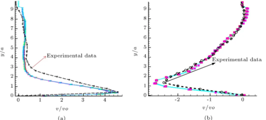
Velocity proles calculated by the numerical model were also compared with the experimental re-sults of Akoz et al. [2]. Table 4 summarizes the experimental and the numerical results. Figure 11 show the distribution of horizontal and vertical ow velocities at a location upstream of the sluice gate compared with experimental results. In this gure velocity and distance from the channel invert were normalized by approach velocity (vo = q=h1) and gate
opening (a) respectively.
Figure 9. Comparison of the discharge coecient calculated by the present model and existing empirical equations and ow 3D numerical simulation.
It can be seen that though the ow is assumed inviscid, the SPH results are reasonably good especially closer to the gate where inertia forces are dominant.
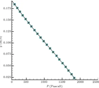
Finally the computed time-averaged pressure dis-tribution on the gate is compared with Roth and Hager Eq. [6] in Figure 12. As can be seen, the prediction of the numerical model for the maximum pressure and trend of the pressure curve agree well with the empirical formula.
As it was mentioned, using IXSPH or articial viscosity leads to the stability of the model. Figure 13 illustrates the ow depth at the inlet calculated by these two techniques with the similar results.
6. Flow simulation under inclined gates
The ow under gates with dierent inclined angles was also simulated by the present model to check its capability in modeling the ow contraction under the gate (Figure 14).
Water surface prole downstream of the gate at an angle of 45 is shown in Figure 15, with less
contraction compared with vertical gate as expected. The ow simulation results for two dierent values of are presented in Figure 16(a) and (b). Computed discharge coecients for dierent gate angles are shown in Table 5. Results show that by decreasing the curvature of the free surface decreases, so that the discharge coecient would increase as expected. Moreover, comparison of contraction coecient for the gate angle of 45 with Montes [22] also shows good
agreement.
Figure 10. A closer view of ow downstream of the gate for dierent unit discharges (m2/s) and a = 5 cm: a) q = 0:0412;
and b) q = 0:0634.
Table 4. Discharge and contraction coecients for experimental and numerical result. Experimental result, Akoz
et al. (2009) [2] Numerical result q (m2/s) a (cm) h
1(cm) Cd Cc h1 (cm) Cd Cc
Figure 11. Comparisons of dimensionless velocities with measurements at the section 1.16a upstream of the gate: a) Horizontal velocity; and b) vertical velocity.
Figure 12. Comparisons of pressure prole on the gate with experimental data for q = 0:0105 (m2/s) and
a = 1:2 cm.
Table 5. Discharge coecients for dierent inclined gates. Present SPH result
(degree) q (m2/s)
a (cm)
h1
(cm) Cd
90 0.0634 5 25 0.577
63.5 0.0634 5 22.8 0.6
45 0.0634 5 21.7 0.616
265 0.0634 5 19.5 0.648
7. Conclusion
Sluice gates are widely used for ow control in open channels. Due to the practical importance of the sluice gates, the prediction of scale discharge relationship and ow characteristics, such as free surface location, is one of the classical problems in hydraulic engineering. The literature shows that most of the numerical simulation for modeling ow under the gates was conducted by
Figure 13. The ow depth at the inlet calculated by IXSPH technique and articial viscosity technique.
Figure 14. Schematic of the ow domain past an inclined gate.
Eulerian methods. However, prediction of free surface which its location is not known in advance is one of the challenging problems in mesh based Eulerian numerical models.
By considering the ability of the SPH model for ow simulation with free surface, particularly rapidly varied ows, this model was applied for simulation of ow under gates. To increase the stability of the model, IXSPH was introduced. A new technique was also used in the model to impose the desired ow discharge at
Figure 15. Flow particles around the inclined gate for = 45.
Figure 16. Flow simulation around the inclined gate for dierent : a) = 26:5; and b) = 63:5.
the inlet section. In this technique, a vertical plate was assumed at the inlet section whose velocity was adjusted based on the ow depth in each time step. Flow depth at inlet was calculated by the model. To decrease surface waves due to the movement of the inlet particles, the discharge was imposed gradually. A new technique was also applied to impose the slip condition at rigid boundaries and decrease the pressure oscillation in the ow domain.
The result showed that the present model can calculate the scale-discharge relationship of the gate with good accuracy. The prediction of the contraction coecient was also in the range of the experimental and other numerical models. Moreover, predicted velocity and pressure proles by the model were in good agreement with experimental data. Eventually, applying the model to simulate ow under inclined gates with dierent angles yielded reasonable result. References
1. Kim, D.G. \Numerical analysis of free ow past a sluice gate", Journal of Civil Engineering Mech., 11(2), pp. 127-132 (2007).
2. Akoz, M.S., Kirkgoz, M.S. and Oner, A.A. \Experi-mental and numerical modeling of a sluice gate ow", Journal of Hydraulic Research, 47(2), pp. 167-176 (2009).
3. Benjamin, T.B. \On the ow in channels when rigid obstacles are placed in the stream", Journal of Fluid Mechanics, 1, pp. 227-248 (1956).
4. Rajaratnam, N. and Subramanya, K. \Flow equation for the sluice gate", Journal of Irrigation and Drainage Engineering, 93(3), pp. 167-186 (1967).
5. Henderson, F.M. Open Channel Flow, Macmillan, New York (1966).
6. Roth, A. and Hager, W.H. \Underow of standard sluice gate", Journal of Experiments in Fluids, 27, pp. 339-350 (1999).
7. Ataie-Ashtiani, B., Shobeyri, G. and Farhadi, L. \Modied incompressible SPH method for simulating free surface problems", Journal of Fluid Dynamics Research, 40, pp. 637-661 (2008).
8. Monaghan, J.J. \Simulating free surface ows with SPH", Journal of Computational Physics, 110, pp. 399-406 (1994).
9. Monaghan, J.J. \Gravity currents and solitary waves", Journal Physica D, 98, pp. 523-533 (1996).
10. Monaghan, J.J. and Kos, A. \Solitary waves on a Cretan beach", Journal of Waterway, Port, Coastal, and Ocean Engineering, 125(3), pp. 145-154 (1999).
11. Capone, T., Panizzo, A. and Monaghan, J.J. \SPH modelling of water waves generated by submarine
landslides", Journal of Hydraulic Research, 48, Extra Issue, pp. 80-84 (2010).
12. Colagrossi, A., Colicchio, G., Lugni, C. and Brocchini, M. \A study of violent sloshing wave impacts using an improved SPH method", Journal of Hydraulic Research, 48, Extra Issue, pp. 90-104 (2010).
13. De Lee, M., Le Touze, D. and Alessandrini, B. \SPH modeling of shallow-water coastal ows", Journal of Hydraulic Research, 48, Extra Issue, pp. 118-125 (2010).
14. Narayanaswamy, M.S., Crespo, A.J.C.
Gomez-Gesteira, M. and Dalrymple, R.A. \SPHysics-FUNWAVE hybrid hodel for coastal wave propaga-tion", Journal of Hydraulic Research, 48, Extra Issue, pp. 85-93 (2010).
15. Groenenboom, P.H.L. and Cartwright, B.K. \Hydro-dynamics and uid-structure interaction by coupled SPH-FE method", Journal of Hydraulic Research, 48, Extra Issue, pp. 61-73 (2010).
16. Maruzewski, P., Le Touze, D., Oger, G. and Avellan, F. \SPH high-performance computing simulations of rigid solids impacting the free-surface of water", Journal of Hydraulic Research, 48, Extra Issue, pp. 126-134 (2010).
17. Rogers, B.D., Dalrymple, R.A. and Stansby, P.K. \Simulation of caisson breakwater movement using 2D SPH", Journal of Hydraulic Research, 48, Extra Issue, pp. 135-141 (2010).
18. Lopez, D., Marivela, R. and Garrote, L. \SPH model applied to hydraulic structures: A hydraulic jump test case", Journal of Hydraulic Research, 48, Extra Issue, pp. 142-158 (2010).
19. Randles, P.W. and Libersky, L.D. \Smoothed particle hydrodynamics some recent improvements and appli-cations", Journal of Computer Methods in Applied Mechanics and Engineering, 138, pp. 375-408 (1996).
20. Monaghan, J.J. and Lattanzio, J.C. \A rened particle method for astrophysical problems", Astronomy and Astrophysics, 149, pp. 135-143 (1985).
21. Fangmeier, D. and Strelko, T.S. \Solution for gravity ow under sluice gates", Journal Engineering Mechan-ics div ASCE, 94(1), pp. 153-176 (1968).
22. Montes, J.S. \Irrotational ow and real uid eects under planar sluice gates", Journal of Hydraulic Engi-neering, 123(3), pp. 219-232 (1997).
23. Liu, G. and Liu, M., Smoothed Particle Hydrodynam-ics: A Mesh Free Particle Method, World Scientic (2003).
24. Dalrymple, R.A. and Rogers, B.D. \Numerical model-ing of water waves with the SPH method", Journal of Coastal Engineering, 53, pp. 141-147 (2006).
25. Khanpour, M., Zarrati, A.R. and Kolahdoozan, M. \Development of a SPH model for solving basic uid
mechanics problems", Science Series Data Report, 5(2), pp. 2-20 (2013).
26. Belytschko, T., Krongauz, Y., Dolbow, J. and Gerlach, C. \On the completenessof meshfree particle meth-ods", International Journal for Numerical Methods in Engineering, 43, pp. 785-819 (1998).
27. Yoon, H.Y., Koshizuka, S. and Oka, Y. \A particle-gridless hybrid method for incompressible ows", In-ternational Journal for Numerical Methods in Fluids, 30(4), pp. 407-424 (1999).
28. Shakibaeinia, A. and Jin, Y.C. \A weakly compress-ible MPS method for simulation open-boundary free-surface ow", International Journal for Numerical Methods in Fluids, 63, pp. 1208-1230 (2010).
29. Morris, J.P., Fox, J. and Zhu, Y. \Modeling low Reynolds number incompressible ows using SPH", Journal of Computational Physics, 136, pp. 214-226 (1997).
30. Federico, I., Marrone, S., Colagrossi, A., Aristodemo, F. and Antuono, M. \Simulating 2D open-channel ows through an SPH model", European Journal of Mechanics B/Fluids, 34, pp. 35-46 (2012).
31. Speerli, J. and Hager, W.H. \Discussion of irrotational ow and real uid eects under planer gates, by J.S. Montes", Journal of Hydraulic Engineering, 125(2), pp. 208-210 (1999).
32. Barahmand, N. and ValiSamani, H.M. \Optimization methods using non-metric variable and Conjugate method to obtain equations to calculate coecient in sluice gate", National Conf. on Irrigation and Drainage Networks Management, Tehran (2006).
Biographies
Mahdiyar Khanpour is a PhD graduate from Amirk-abir University of Technology. His major eld of interest is Hydraulic Engineering. During his PhD research, he concentrated on numerical modeling of hydraulic structure and scouring downstream of gates by Lagrangian viewpoint. Moreover, he is interested in sediment transport simulation, such as jet scouring and ashing of reservoirs. In addition to numerical simula-tion, some experimental modeling was also conducted during his PhD study.
Mr. Khanpour has received his MSc from Iran University of Science and Technology. During the Mas-ter degree course, he focused on numerical modeling of sediment transport. This research was based on a Lagrangian (DEM) method.
Amir Reza Zarrati is a professor of Hydraulic En-gineering at the Department of Civil and Environmen-tal Engineering, Amirkabir University of Technology Tehran, Iran. He has more than 20 years of teaching
and research experience. His main area of research is numerical and physical modeling of ow behavior, such as in hydraulic structures and rivers. He is also interested in scouring phenomenon and methods of its control. Dr. Zarrati has also a long collaboration with industry and has been senior consultant in a number of large dams in the country. Dr. Zarrati is a member of Iranian Hydraulic Association (IHA) and International Association of Hydraulic Research (IAHR).
Morteza Kolahdoozan is currently a faculty
mem-ber at the Department of Civil and Environmental Engineering, Amirkabir University of Technology. His main area of research is uid mechanics, coastal hy-drodynamics and sediment transport, water quality evaluation, numerical and physical modeling of coastal, estuarial and riverine phenomena. He has a reputed collaboration on research projects with industry and also is senior consultant of a number of governmental bodies, namely; Ministry of Energy and Ministry of Transportation. He is also a member of Iran Hydraulic Association and Iranian society of Marine engineers.