Sharif University of Technology
Scientia IranicaTransactions B: Mechanical Engineering www.scientiairanica.com
Forward kinematic problem of three 4-DOF parallel
mechanisms (4-PRUR1, 4-PRUR2
and 4-PUU) with
identical limb structures performing 3T1R motion
pattern
P. Varshovi-Jaghargh
a, D. Naderi
a;and M. Tale-Masouleh
ba. Department of Mechanical Engineering, Bu-Ali Sina University, Hamedan, P.O. Box 65175-4161, Iran.
b. Department of Mechatronics, Human and Robot Interaction Laboratory, Faculty of New Sciences and Technologies, University of Tehran, Tehran, Iran.
Received 11 September 2012; received in revised form 7 December 2013; accepted 26 February 2014
KEYWORDS Parallel mechanism; 3T1R motion pattern; Schonies motion; Forward kinematic problem;
Three-dimensional Euclidean space.
Abstract. This paper investigates the forward kinematic problem of three 4-DOF parallel mechanisms performing three translations and one rotation motion, referred to as Schonies motion. The kinematic arrangements of the mechanisms under study in this paper are such that two of them are classied as 4-PRUR and one of them is a 4-PUU. They are, respectively, special cases of 4-PR0R0R00R00, 4-PR00R00R0R0 and
4-PR00R0R0R00 parallel mechanisms that have originated from the type synthesis of 4-DOF
parallel mechanisms with identical limb structures. The forward kinematic problem is studied in three-dimensional Euclidean space, and a univariate expression describing the forward kinematic problem is obtained for each of the latter parallel mechanisms by the resultant method. The results obtained from this method show that a set of univariate expressions of degree (72, 64, 64, 82, 4, 28) describes the forward kinematic problem of
4-PRUR1 and 4-PRUR2 parallel mechanisms. Also, a quadratic univariate expression
represents the forward kinematic problem of 4-PUU parallel mechanisms. In addition, the system of equations corresponding to the forward kinematic problem is solved upon resorting to a homotopy continuation approach, which claries that the forward kinematic problems of 4-PRUR1, 4-PRUR2 and 4-PUU parallel mechanisms admit up to 236, 236
and 2 nite solutions, real and complex.
© 2014 Sharif University of Technology. All rights reserved.
1. Introduction
A Parallel Mechanism (PM) is a closed-loop kinematic chain mechanism, whose end-eector is linked to the base by several independent kinematic chains [1]. PMs have been used in a wide variety of applications,
*. Corresponding author. Tel.: +98 811 8257410; Fax: +98 811 8257400
E-mail addresses: [email protected] (P.
Varshovi-Jaghargh); d [email protected] (D. Naderi); [email protected] (M. Tale-Masouleh)
such as ight simulators [2,3], machine tools [4], industrial robots [5], twists [6], high-performance camera-orienting devices [7], wire robots [8], min-ing mechanisms [9], medical devices [10], micro-manipulators [11,12] and nano-micro-manipulators [13]. In comparison with serial mechanisms, properly designed PMs generally have higher stiness and accuracy [14]. However, there are some major deterrents to the widespread use of PMs in industrial applications, such the presence of extensive singularity congurations in their restricted workspace [15].
application of a six-legged PM dates back to the 1950's, when a tire testing machine was developed by Gough [16], based on a PM. However, today, the prevalence of PM applications calls for the develop-ment of mechanisms with fewer numbers of DOF or limited-DOF [17]. In comparison with a 6-DOF PM, a limited-DOF PM has the advantages of a simple mechanical structure, low manufacturing cost, simple control algorithms, and a larger workspace and high-speed capability [18]. The study of limited-DOF PMs, such as 4-DOF PMs, has recently become a main focus among the robotics research community, because this type of PM has many industrial applications, such as Pick and Place operations [19].
The development of this type synthesis channels researchers to synthesize lower-mobility parallel mech-anisms, since it was believed that parallel mechanisms with identical limb structures, i.e. topologically sym-metrical, with 4- and 5-DOF, could not be built. In general, 4-DOF PMs are a class of PMs with reduced DOF, which, according to their mobility, fall into three motion patterns: (1) three translational and one rota-tional DOF (3T1R), (2) two translarota-tional and two ro-tational DOF (2T2R) and (3) three roro-tational and one translational DOF (3R1T) [14,20]. The 3T1R motion pattern, referred to as SCARA motion or Schonies motion, consists of all translations, as well as rotations, about any axis in a given xed direction [21]. In the late 1990's, researchers believed that general limited-DOF PMs could not be constructed with identical limb structures (A PM with identical limb structures consists of a mechanism where all the limbs follow the same imposed kinematic arrangement to realize the desired motion pattern. The kinematic limb structure or kinematic chain consists of the placement order and type of joint), as pointed out by Hunt [22] and Tsai [23]. Therefore, some 4-DOF PMs with non-identical limb
structures have been reported. Hesselbach et al.
in [24] introduced a 4-DOF PM with non-identical limb structures with two limbs for cutting convex glass panels. In [25], Rolland proposed two 4-DOF PMs, called Kanuk and Manta, both of which possess 3T1R
DOF. Lenarcic et al. in [26] used a 4-DOF PM
with one PS and three SPS limbs to simulate the shoulder of a humanoid. But, PMs with non-identical limb structures result in an asymmetrical workspace, which may complicate task planning. Hence, several researchers have made great eorts in designing 4-DOF PMs with identical limb structures, based on intuition and engineering skills. One of the earliest 4-DOF PM with identical limb structures is the Delta robot presented by Clavel in [27], which performed the so-called Schonies motion. Company and Pierrot, in [28], presented a new PM whose platform performs 3T1R, and Pierrot et al., in [29], introduced a family of 4-DOF PMs with identical limb structures using the
parallelogram concept. It should be noted that the rst 4-DOF PM with four identical limb structures, performing a 3R1T motion pattern, was proposed by Zlatanov and Gosselin in [30], which comprises four RRRRR limbs; three intersecting and two parallel revolute joints.
All the aforementioned architecture was devel-oped mainly based on engineering perception. Re-cently, several systematic approaches, such as screw theory [31], displacement group theory [32], single-opened-chain units [33], the virtual-chain approach [34] and the constraint-synthesis method [35,36], have been proposed for a type synthesis of PM in order to obtain all possible types of PM with a specic motion pattern. In [37], Fang and Tsai employed the screw theory and reciprocal screws for the structural synthesis of a given class of 4-DOF PMs with identical limb structures. In [14,20], Kong and Gosselin created a type synthesis of PM with special motion patterns and identical limb structures, based on screw theory and the virtual chain approach. Thus, the main concern in the analysis of PMs with identical limb structures was the type synthe-sis and this can be exemplied from the large number of papers published on this issue. However, there are still some gaps in their kinematic properties including, among others, the Forward Kinematic Problem (FKP). FKP, one of the challenging issues on the kinematics of PMs, pertains to nding the pose of the platform for a given set of actuated joints [38]. The position and orientation of the platform of a PM in space are, collectively termed, the pose.
In the past two decades, several algorithms and methods have been presented for solving the FKP of PMs. In [39], Gosselin and Merlet obtained a six degree polynomial for the FKP of the 3-RPR planar PM and proposed two simplied mechanisms in which the FKP of each one leads to a maximum of four real solutions. In [40,41], Husty and Schroker solved the FKP of general Gough-Stewart platforms using kinematics mapping introduced by Study [42], for the rst time. This algorithm maps three dimensional motions to the seven-dimensional, quasi-elliptic space. The results reported in [40,41] reveal that the upper bound of the number of solutions for the Gough-Stewart platform is 40. In [43], Merlet revealed the problem of nding all the solutions of the FKP for every possible architecture of planar fully PMs. In [44], Tanev studied the FKP of a 4-DOF PM with one RRPR and two SPS limbs. Neural networks have been used for the FKP of PMs [45,46]. Lee and Shim in [47] proposed an algorithm for the FKP of a Stewart PM using the elimination theory, which is suitable for real time proposes. Richard et al., in [48], studied the FKP of a 3T1R 4-DOF PM, called Quadrupteron. They demonstrated that the FKP of Quadrupteron requires the solution of a univariate quadratic equation.
Masouleh et al., in [49], investigated the FKP of 5-RPUR PM. Moreover, in [50], Tale Masouleh et al. proposed an algorithm based on the study parameters, referred to as the Linear Implicitization Algorithm (LIA), for obtaining, systematically, the Forward Kine-matic Expression (FKE). The FKP of 5-DOF PMs (3R2T) with identical limb structures was investigated using this algorithm, i.e. LIA [38]. It should be noted that the FKE is a mathematical expression that pertains to nding the pose(s) for a given limb to reach given actuator coordinates.
To the best knowledge of the authors, until now, very few kinematic studies have been conducted on 4-DOF PMs with identical limb structures. This is
probably due to their short history. Also, in an
industrial context, 3T1R motion can cover a wide range of applications, including, among others, Pick-and-Place operations. In addition, the analytical solution of FKP in the context of PMs, due to its mathematical complexity, initiated much research, both in mathe-matics and mechanics. Accordingly, in this paper, the FKP of two 4-PRUR PMs with dierent geometric structures, and one 4-PUU PM performing a 3T1R motion pattern, are investigated using two approaches. In the rst approach, the resultant method is used toward obtaining the FKE for each limb, and the FKP for the mechanism as a whole. The FKE of each limb should be free of passive variables, i.e., non-actuated joint coordinates. Accordingly, more empha-sis is placed on the kinematic modeling of one limb. Moreover, the results obtained with the latter approach for the FKP are veried using Bertini software based on homotopy continuation. Finally, the real solutions obtained from the two approaches are compared with each other and their congurations are depicted in the CAD environment.
The remainder of this paper is organized as follows: The architecture and the general kinematic properties of three 4-DOF PMs that originated from the type synthesis performed in [14] are rst out-lined. Then, the FKP analyses of these PMs are fully investigated with the aim of obtaining a univariate expression for each case. For the sake of compar-ison, for dierent case studies, the FKP analysis is carried out by resorting to a homotopy continuation
method. Finally, the paper concludes with some
remarks and analysis on the results obtained for the FKP.
2. Geometric architecture and kinematic modelling
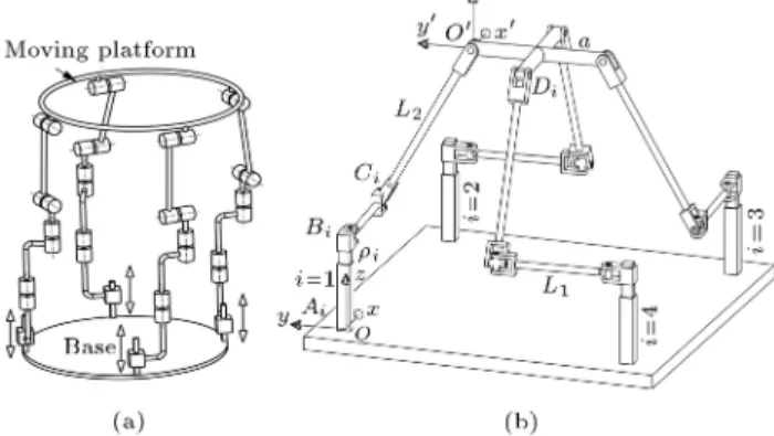
Figures 1(a), 2(a) and 3(a) provide, respectively, a schematic representation of 4-PR0R0R00R00,
4-PR00R0R0R00 and 4-PR00R00R0R0 PMs. Here, and
throughout this paper, R, P and U joints stand,
re-Figure 1. (a) Schematic representation of a
4-PR0R0R00R00PM [14]. (b) CAD model of a 4-PRUR 1
PM.
Figure 2. (a) Schematic representation of a
4-PR00R00R0R0 PM [14]. (b) CAD model of a 4-PRUR 2
PM.
Figure 3. (a) Schematic representation of a
4-PR00R0R0R00PM [14]. (b) CAD model of a 4-PUU PM.
spectively, for revolute, prismatic and universal joints, where the underlined one is actuated. Moreover, joints with the same superscript have parallel axes. The mentioned PMs have been originated from the type synthesis performed for the PMs having 3T1R as the
motion pattern [14]. Figures 1(b), 2(b) and 3(b)
depict the CAD model of 4-P RUR1, 4-PRUR2 and
PUU PMs that are, respectively, special cases of 4-PR0R0R00R00, 4-PR00R0R0R00 and 4-PR00R00R0R0 4-DOF
PMs performing a 3T1R motion pattern. The input of the mechanism is provided by the four linear prismatic actuators xed at the base. In addition, four passive revolute joints are in each limb.
reference frame, Oxyz, is attached to the base of the
mechanism with i, j and k as its unit vectors, and a moving reference frame (mobile frame), O0
x0y0z0, is
attached to the moving platform. In this paper, the superscript 0 stands for a vector representation in the
mobile frame. The three mentioned PMs provide all three translations DOF plus one independent rotation DOF of the end-eector, namely, x, y, z and , that are known as the pose (position and orientation) of the platform. Indeed, they are limited-DOF PMs, which cannot rotate about any axis that is parallel to x- and y-axes. In the latter notation, x, y and z represent the translational DOF, with respect to the xed frame O, illustrated in Figures 1(b), 2(b) and 3(b). (rotation from the xed frame, Oxyz, to
the moving frame, O0
x0y0z0) stands for the orientation
DOF around z-axes (the vertical axis). In the ith limb, the extension of the actuated prismatic joint is measured, with respect to the reference point, Ai, located on the base, by the joint coordinate,
i, which is the signed distance between point Ai
and reference point Bi attached to the prismatic
joint.
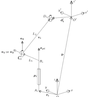
Figures 4, 5 and 6 represent, respectively, the
schematic of PRUR1, PRUR2 and PUU limbs. The
vectors, e1, e2, e3 and ei, are dened as the unit
vectors in the directions of the revolute joints parallel to the x-axis, the revolute joint parallel to the y-axis, the revolute joint parallel to the e1 e2 axis and the
prismatic joint, respectively. Therefore, the vector connecting point Ai to point Bi can be written as
i = iei(AiBi ? e1; e2). Vector ri (a constant
vector) is dened as the position vector of point Ai
in the xed reference frame. Similarly, vector d0 iis the
vector connecting point O0 of the mobile platform to
Figure 4. Schematic representation of a PRUR1 limb.
Figure 5. Schematic representation of a PRUR2 limb.
Figure 6. Schematic representation of a PUU limb.
a reference point Di on the axis of the last revolute
joint of the ith limb. Vectors uiand viare the vectors
connecting point Ci to point Di and point Di to point
Ei, respectively, and the magnitude of vectors ui and
viare, respectively, L1and L2. Finally, the position of
the platform is represented by vector p =x; y; zT, connecting point O to point O0, and the orientation of
the moving frame, with respect to the xed frame, is given by a rotation matrix, Q:
Q = 0
@cos sin cos sin 00
0 0 1
1
A : (1)
computed, and vector d0
iis then obtained as:
di= Qd0i: (2)
2.1. Kinematic modelling of 4-PRUR1 PM
Figure 4 provides a schematic representation of a
PRUR1 limb. From the type synthesis presented
in [14], the geometric characteristics associated with the components of each limb of a 4-PRUR1PM are as
follows: The four revolute joints attached to the moving platform (the last R joints in each of the limbs) have parallel axes, the four prismatic joints attached to the base have parallel axes, eijjz, the rst two revolute
joints of each limb have parallel axes, and the last two revolute joints of each limb have parallel axes, e2jjz. It should be noted that the second and third
revolute joints in each limb are built with intersecting and perpendicular axes and are, thus, assimilated to a U joint. In addition, the direction of the P joint is parallel to the last two R joints and perpendicular to the axis of its adjacent R joint.
e1= Qe01=
sin cos 0T; (3)
e2= Qe02=
cos sin 0T: (4)
2.2. Kinematic modelling of 4-PRUR2 PM
In this case, as observed in Figure 5, the prismatic actuator is parallel to the z-axes, eijjz. The rst
and second revolute joints of each limb have parallel axes that are perpendicular to the x y plane, e3jjz.
The third and fourth revolute joints of each limb have parallel axes in which they are parallel to the x y plane, e10 ? z and e2? z. Similar to 4-PRUR1 PM,
the second and third revolute joints of each limb can be replaced by a universal joint (point Ci).
2.3. Kinematic modelling of a 4-PUU PM Figure 6 represents, schematically, a limb of a 4-PUU PM. It is worth noticing that this kinematic arrange-ment is used for the so-called Quadrupteron [51], be-longing to the n-petron orthogonal PMs [52], which has some remarkable kinematic properties. The direction of each prismatic actuator, the rst and fourth R joints in each limb parallel to the z-axis, and the directions of the second and third R joints in each limb are perpendicular to the z-axis (vi? e1 or vi? e2). The
rst and second joints, and the third and fourth joints, have perpendicular axes and each two joints form a U joint (Figure 6).
3. Forward Kinematic Problem (FKP)
The FKP pertains to nding the pose of the moving platform for a given set of actuated joints [38]. The study of the FKP of the PM requires a suitable mathematical framework in order to describe both
translations and rotations in a most general way [50]. In this investigation, the FKP is studied in three-dimensional Euclidean space. It should be noted that the FKP is solved in polynomial form, when it is made equivalent to determining the roots of a univariate polynomial equation [40,53]. In what follows, rst, the FKE for each limb of the PM under study is obtained using the coordinates of the joints and the kinematic constraints. The FKE should be free of the passive joint coordinates, i.e. joints whose positions are not known from the outset. Then, a univariate expression describing the FKP of the PM is obtained using the FKEs and upon resorting to the so-called resultant method. Resultant is an alternative approach to the problem of elimination. In summary, if f and g are two polynomials with a positive degree, written as Eqs. (5) and (6), then, the resultant of f and g, denoted by Res (f; g), is the (l + m) (l + m) determinant [54]:
f = a0xl+ ::: + al; a06= 0; l > 0; (5)
g = b0xm+ ::: + bm; b06= 0; m > 0; (6)
Res(f; g) = det 0 B B B B B B B B B B B B B B B @
a0 b0
a1 a0 b1 b0
a2 a1 ... b2 b1 ...
... a2 ... a0 ... b2 ... b0
al ... ... a1 bm ... ... b1
al ... a2 bm ... b2
... ... ... ...
al bm
1 C C C C C C C C C C C C C C C A ; (7)
where the blank spaces are lled with zeros and ai
and bi are constant coecients or polynomials. Thus,
Res (f; g; x) stands for the resultant of f and g by eliminating the variable, x.
3.1. Forward kinematic problem of 4-PRUR1
The following relations hold for the coordinate of points Ai and Di for all the mechanisms under study in this
paper:
xAi yAi zAiT = rAi for i = 1; 2; 3; 4; (8)
xDi yDi zDiT = p + Qd0i: (9)
In the above, rAi is the vector connecting O to Ai.
Since Di is attached to the platform, its coordinates
can be written directly in terms of the platform pose for the three PMs. Moreover, d0
iis the position vector
With reference to Figure 4, the following equa-tions, arising from the kinematic constraint of the ith limb, can be written as:
zBi zAi i= 0; (10)
BiCi=(yCi yBi)2+ (zCi zBi)2 L21= 0
for i = 1; 3; (11)
BiCi=(xCi xBi)2+ (zCi zBi)2 L21= 0
for i = 2; 4; (12)
CiDi= (xDi xCi)2+ (yDi yCi)2 L22= 0: (13)
In the above, the last four equations represent, re-spectively, the magnitude of vectors, i and ui, of
the 1st and 3rd limbs, ui of the 2nd and 4th limbs,
and vi. According to the FKP analysis, the above
system of equations should be solved in terms of the pose of the platform with respect to input data, which are the lengths of the prismatic actuators, i, and the
design parameters. To this end, the coordinates of all passive joints (Bi, Ci and Di) should be eliminated
from Eqs. (11)-(13).
The coordinates of Di can be obtained from
Eq. (9), with respect to the pose of the platform. The vector, p, of Eq. (9) is the position of the moving frame in a xed frame that is represented by vector p =
x; y; zT. Moreover, d0
i of Eq. (9) is the position
vector of point Di in the moving frame that can be
written as d0 1 =
0; 0; 0T , d0 2 =
a; a; 0T,
d0 3 =
0; 2a; 0T and d0
i=
a; a; 0T. One
of the kinematic constraints applied to all limbs can be expressed as vi ? e3, which leads to zCi = zDi.
Another constraint of the rst and third (second and fourth) limb is ui ? e1(ui ? e2), which results in
xCi= xBi= xAi(yCi= yBi= yAi). In addition, there
are two other constraints in the form of zBi= zAi+ i
and yBi = yAi, which result from the geometry of all
three mechanisms.
The following equations can be written for the rst limb, i = 1, by substituting zC1 = z, yB1 = yA1,
zB1 zA1+ 1 and zA1 = 0 (derived from the above
kinematic constraints) into Eq. (11) and replacing xD1 = x, yD1 = y and xC1 = xA1 (derived from the
above kinematic constraints) into the Eq. (13):
B1C1= z2 2z1 L21+ 21+ y2A1 2yA1yC1+ y2C1;
(14) C1D1= x2 2xxA1+ y2 2yyC1 L22+ x2A1+ y2C1:
(15) Coordinate yC1is unknown in Eqs. (14) and (15), which
can be eliminated by a resultant method, and the FKE
of the rst limb, Eq. (16), can be obtained in the terms of platform pose, input variable, 1, design parameters,
L1 and L2, and coordinates of point A1(xA1; yA1)
attached to the base:
F1=Res(B1C1; C1D1; yC1) = x4+ 2x2y2 2x2z2
+ y4+ 2y2z2+ z4+ 4
1x2z 41y2z 41z3
2L2
2x2 221x2+ 2L21x2 2L22y2+ 221y2
2L2
1y2 2L21z2+ 621z2+ 2L22z2+ 41L21z
41L22z 431z+41+L24 2L21L22+221L22
+L4
1 2L2121: (16)
As observed from the above equation, angle does not appear in the equations of the 1st limb, because the origin of the moving frame is attached to point D1, and
d0 1=
0; 0; 0T. For the second limb, the following equations can be written from Eqs. (12) and (13):
B2C2=z2 2z2 L12+ 22+ x2A2 2xA2xC2
+ x2
C2; (17)
C2D2=x2+ y2+ 4sx 2xC2x + 4cx 2acy
2yA2y+2asy 2a2cs 2asyA2+ a2
+ 2acyA2 L22+ 8cs 4cxC2
4sxC2+ x2C2+ yA22 + 4; (18)
where, in the above equations, s = sin and c =
cos . After obtaining the equations of BiCiand CiDi,
the FKE of the second to fourth limb, called Fi, i =
2; 3; 4, in terms of platform pose, input variable, i,
design parameters, L1, L2, a, xAi, and yAi, can be
obtained as follows:
F2= Res(B2C2; C2D2; xC2); (19)
F3= Res(B3C3; C3D3; yC3); (20)
F4= Res(B4C4; C4D4; xC4): (21)
Finally, the following operations are performed to obtain a univariate expression for the FKP:
F12(y; z; t) = Res(F1; F2; x); (22)
F13(y; z; t) = Res(F1; F3; x); (23)
F1213(z; t) = Res(F12; F13; y); (25)
F1214(z; t) = Res(F12; F14; y); (26)
Fk(t) = Res(F1213; F1214; z); (27)
Fk(t) =
0
@n
i=1
0 @Xm
j=1
(jtj)k
1 A
1
A ; (28)
Fk(t) is the univariate expression based on the variable
t, where t = tan(=2), sin = 2t=(1 + t2), and cos =
(1 t2)=(1+t2) is the tan-half substitution. In Eq. (28),
j is the constant coecient, depending on the
de-sign parameters. Numerous random examples have been solved for the 4-PRUR1 PM using the resultant
method, and it should be noted that the univariate
expression of a 4-PRUR1 PM always consists of 6
separated polynomials with respect to t, of degree 72, 64, 64, 82, 4 and 28, so that these polynomials contain
the FKP answer. Polynomials of degree 82 and 28,
re-spectively, mean a polynomial of degree 8 to the power of 2 and a polynomial of degree 2 to the power of 8.
It should be explained that, in all examples, there is one set of forward kinematic solutions for every answer obtained from the polynomial of the univariate expression to the power of one. Also, there are m sets of solution for every answer obtained from a polynomial of degree n to the power of m. Thus, there is one solution of the FKP for every answer obtained from the polynomial of degree 72, 64, 64 and 4. However, two sets of solutions are obtained from each answer of the polynomial of degree 8, and eight sets of solutions are resulted from each answer of the polynomial of
degree 2. Indeed, the total degree of polynomials of degree 8 to the power of 2 and degree 2 to the power of 8 are, respectively, 8 2 = 16 and 2 8 = 16. It means that each polynomial has 16 sets of forward kinematic solutions. Finally, the total degree of these univariate polynomials, in each example, is 236 (72 + 64 + 64 + 8 2 + 4 + 2 8 = 236), which demonstrated that a general 4-PRUR1 PM admits up
to 236 solutions, real and complex. Moreover, the FKP of a 4-PRUR1 PM is investigated using Bertini
software, which obtains the numerical solution of the system of polynomial equations using the homotopy continuation approach [55]. In this procedure, all expressions and kinematic equations obtained, in terms of the platform poses (x; y; z and ) and coordinates of passive variables (xCi; yCi and zCi), are as input
equations (16 equations and 16 unknowns). In each example, 236 solutions, real and complex, are obtained using Bertini software. The results show that all 236 solutions, real and complex, obtained from the two approaches perfectly match each other. In addition, all the solutions were placed in the inverse kinematic equations and the FKP result is conrmed.
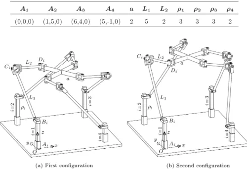
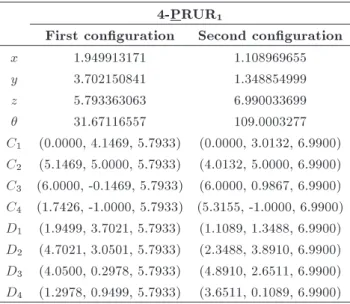
As an example, 10 real and 226 complex solutions have been obtained for the values given in Table 1 for this PM using two approaches. It should be noted that, in this case, two of the real nite solutions result from the polynomial of degree 72, two of them result from the rst polynomial of degree 64, two of them result from the second polynomial of degree 64, and four of them result from the polynomial of degree 8. For example, two congurations of 4-PRUR1 PM, in this
case, are given in Table 2 and Figure 7.
Table 1. The design parameters, prismatic elongations and coordinates of Aifor the 4-PRUR1 PM under study.
A1 A2 A3 A4 a L1 L2 1 2 3 4
(0,0,0) (1,5,0) (6,4,0) (5,-1,0) 2 5 2 3 3 3 2
Table 2. Two solutions, among ten, obtained for the FKP of 4-PRUR1using the two approaches.
4-PRUR1
First conguration Second conguration
x 1.949913171 1.108969655
y 3.702150841 1.348854999
z 5.793363063 6.990033699
31.67116557 109.0003277
C1 (0.0000, 4.1469, 5.7933) (0.0000, 3.0132, 6.9900)
C2 (5.1469, 5.0000, 5.7933) (4.0132, 5.0000, 6.9900)
C3 (6.0000, -0.1469, 5.7933) (6.0000, 0.9867, 6.9900)
C4 (1.7426, -1.0000, 5.7933) (5.3155, -1.0000, 6.9900)
D1 (1.9499, 3.7021, 5.7933) (1.1089, 1.3488, 6.9900)
D2 (4.7021, 3.0501, 5.7933) (2.3488, 3.8910, 6.9900)
D3 (4.0500, 0.2978, 5.7933) (4.8910, 2.6511, 6.9900)
D4 (1.2978, 0.9499, 5.7933) (3.6511, 0.1089, 6.9900)
3.2. Forward kinematic problem of a
4-PRUR2 PM
Using the same reasoning as above, from Figure 5, one has the following for the 4-PRUR2 PM:
zBi zAi i= 0; (29)
(xCi xBi)2+ (yCi yBi)2 L21= 0; (30)
(xDi xCi)2+(yDi yCi)2+(zDi zCi)2 L22= 0:
(31) Since the FKP is of concern, the values of the prismatic actuators, i.e. the coordinates of points Bi, are known.
The coordinates of points Di can be obtained from
Eq. (9), in terms of platform pose. But, the coordinates of points Ci are not known and should be eliminated
from Eqs. (29)-(31) based on the constraints of each limb. The rst constraint of the limb is vi ? e3
which leads to zCi = zBi. The direction of vi(CiDi)
always makes an angle, , with respect 1to the x-axis. Therefore, the second constraint is written as follows for each limb:
xC1= xD1 1s; yC1= yD1+ 1c; (32)
xC2= xD2+ 2c; yC2= yD2+ 2s; (33)
xC3= xD3+ 3s; yC3= yD3 3c; (34)
xC4= xD4 4c; yC4= yD4 4s; (35)
where, in this equation, i is the image of vi on
the x y plane, as depicted in Figure 8. Eqs. (30) and (31) are written for the rst limb after substituting the coordinates of points Ci (obtained in the previous
paragraph):
B1C1= x2+ y2 21cx 21sy + 21 L21; (36)
Figure 8. The image of vi(CiDi) on the x y plane.
C1D1= z2 21z L22+ 12+ 21: (37)
The FKE of the rst limb is obtained by applying the resultant method to the above equations:
F1=Res(B1C1; C1D1; 1) = x4+ 2x2y2+ 4c2x2z2
2x2z2+ 8c
sxyz2+ y4+ 4s2y2z2 2y2z2
+ z4+ 4
1x2z 8c21x2z 16cs1xyz
8s2
1y2z+41y2z 41z3 221x2+2L22x2
+4c2
21x2 4c2L22x2 2L21x2 8csL22xy
+ 8cs21xy 4s2L22y2+ 4s221y2+ 2L22y2
2L2
1y2 221y2+ 621z2+ 2L21z2 2L22z2
+41L22z 431z 41L12z 2L21L22+ 221L21
+ L4
1+ 41 2L2221+ L42: (38)
Moreover, the tan-half substitution, t = tan(=2), is used and, nally, a univariate expression is obtained, with respect to t.
Fk(t) =
0
@n
i=1
0 @Xm
j=1
(#jtj)k
1 A
1
A : (39)
In the above equation, #j is a constant coecient that
consists of design parameters. Numerous random ex-amples were solved and the following result is obtained: The univariate expression of a 4-PRUR2 PM consists
of polynomials in degrees of 72, 64, 64, 82, 4 and 28
with respect to t. These polynomials contain, always, the answer of FKP. In addition, the FKP is solved by Bertini, and 236 solutions, real and complex, are obtained. The results obtained from two approaches
demonstrate that the FKP of the 4-PRUR2 PM, the
same as the FKP of the 4-PRUR1 PM, has up to 236
Table 3. The design parameters, prismatic elongations and coordinates of Aifor the 4-PRUR2 PM under study.
A1 A2 A3 A4 a L1 L2 1 2 3 4
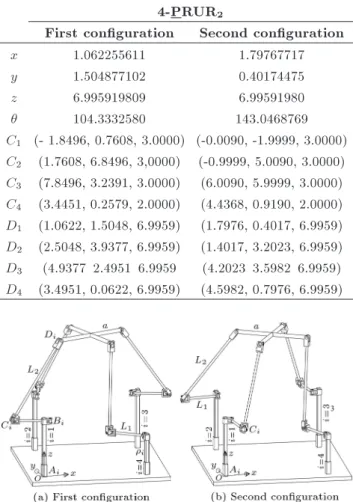
(0,0,0) (1,5,0) (6,4,0) (5,-1,0) 2 2 5 3 3 3 2 Table 4. Two solutions, among eighteen, obtained for the
FKP of 4-PRUR2 using the resultant method.
4-PRUR2
First conguration Second conguration
x 1.062255611 1.79767717
y 1.504877102 0.40174475
z 6.995919809 6.99591980
104.3332580 143.0468769
C1 (- 1.8496, 0.7608, 3.0000) (-0.0090, -1.9999, 3.0000)
C2 (1.7608, 6.8496, 3,0000) (-0.9999, 5.0090, 3.0000)
C3 (7.8496, 3.2391, 3.0000) (6.0090, 5.9999, 3.0000)
C4 (3.4451, 0.2579, 2.0000) (4.4368, 0.9190, 2.0000)
D1 (1.0622, 1.5048, 6.9959) (1.7976, 0.4017, 6.9959)
D2 (2.5048, 3.9377, 6.9959) (1.4017, 3.2023, 6.9959)
D3 (4.9377 2.4951 6.9959 (4.2023 3.5982 6.9959)
D4 (3.4951, 0.0622, 6.9959) (4.5982, 0.7976, 6.9959)
Figure 9. Schematic representation of two congurations for the FKP of a 4-PRUR2 PM represented in Table 4.
complex, were placed in the inverse kinematic equa-tions and the accuracy of the results has been proved. For example, for the values given in Table 3, the FKP of the 4-PRUR24 PM has 236 solutions (18 real
and 218 complex solutions). It can be noted that, in this example, two of the real solutions result from the polynomial of degree 72, four of them result from the rst polynomial of degree 64, four of them result from the second polynomial of degree 64, four of them result from the polynomial of degree 8, two of them result from the polynomial of degree 4 and two of them result from the polynomial of degree 2. As an example, two congurations of the 4-PRUR2 PM under study are given in Table 4 and Figure 9.
3.3. Forward kinematic problem of 4-PUU With reference to Figure 6, the following can be written for the ith limb of a 4-PUU PM:
Figure 10. Schematic representation of two
congurations for the FKP of a 4-PUU PM represented in Table 4.
zBi zAi i= 0; (40)
(xDi xCi)2+(yDi yCi)2+(zDi zCi)2 L22= 0:
(41) The coordinates of Di can be obtained from Eq. (9),
with respect to the pose of the platform. Thus, the FKE of the rst limb can be written as follows:
F1= x2+ y2+ z2 2L1y 21z + L21+ 21 L22:
(42) Similarly, the FKE of the second limb is obtained as follows:
F2=x2+ y2+ z2 4cx + 4sx 2xA2x 2L1x
4cy + 4sy 2yA2y 22z + L21 4L1c
4L1s+ 2L1xA2 L22 4cxA2+ 4cyA2
+ 2
2 4sxA2 4syA2+ x2A2+ yA22 + 8: (43)
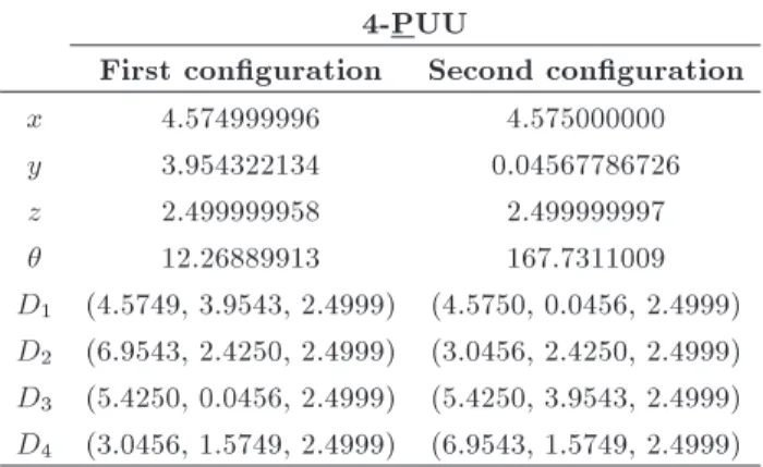
Finally, the univariate expression describing the FKP of a 4-PUU PM is obtained as a univariate quadratic expression by applying the tan-half substitution, t = tan(=2), and using Eqs. (22) to (27). Therefore, a second degree polynomial is constantly describing the FKP of 4-PUU PM, which is consistent with the result obtained in [51]. Moreover, the number of solutions of the FKP, real and complex, obtained by Bertini is equal to 2. Numerous random examples have been solved for the 4-PUU PM using the resultant method and the homotopy continuation approach, and this result is conrmed by them. In addition, the results of each example are conrmed by placing solutions of FKP in the inverse kinematic problem equations. For example, for the values given in Table 5, the FKP of the 4-PUU PM have 2 real solutions (Table 6), both of whose congurations are represented in Figure 10.
Table 5. The design parameters, prismatic elongations and coordinates of Ai for the 4-PUU PM under study.
A1 A2 A3 A4 a L1 L2 1 2 3 4
(0,0,0) (3,7,0) (10,4,0) (7,-3,0) 2 2 5 3 3 3 2 Table 6. The only two solutions obtained for the FKP of
4-PUU using the resultant method. 4-PUU
First conguration Second conguration
x 4.574999996 4.575000000
y 3.954322134 0.04567786726
z 2.499999958 2.499999997
12.26889913 167.7311009
D1 (4.5749, 3.9543, 2.4999) (4.5750, 0.0456, 2.4999)
D2 (6.9543, 2.4250, 2.4999) (3.0456, 2.4250, 2.4999)
D3 (5.4250, 0.0456, 2.4999) (5.4250, 3.9543, 2.4999)
D4 (3.0456, 1.5749, 2.4999) (6.9543, 1.5749, 2.4999)
4. Conclusions
This paper investigated the FKP of three kinds of
4-DOF PMs, 4-PRUR1, 4-PRUR2 and 4-PUU, with
identical limb structures performing a 3T1R motion pattern, or the so-called Schonies motion, using the resultant method and the homotopy continuation
approach. From this study, it follows that a set
of univariate expressions of degree (72, 64, 64, 82,
4, 28) describe the FKP of 4-PRUR
1 and 4-PRUR2
PMs, which demonstrated that the FKP of both PMs
have up to 236 solutions. Also, a second degree
univariate polynomial represents the solutions for the FKP of a 4-PUU PM. Moreover, upon resorting to Bertini software for solving polynomial systems using the homotopy continuation approach, it was conrmed
that the FKP of a 4-PRUR1, 4-PRUR2 and 4-PUU
admit 236, 236 and 2 nite solutions, real and complex. The results obtained from the two approaches reveal that the solutions to the FKP can be in dierent sets of univariate expression obtained using the resultant method. Ongoing work includes the design of an optimum 4-DOF PMs.
References
1. Merlet, J.-P., Parallel Robots, Springer,
Sophia-Antipolice, France (2006).
2. Stewart, D. \A platform with six degrees of freedom",
Proceedings of the Institution of Mechanical Engineers, 180(1), pp. 371-386 (1965).
3. Pouliot, N.A., Gosselin, C.M. and Nahon, M.A.
\Mo-tion simula\Mo-tion capabilities of three-degree-of-freedom ight simulators", Journal of Aircraft, 35(1), pp. 9-17 (1998).
4. Huang, T., Whitehouse, D. and Wang, J. \The local
dexterity, optimal architecture and design criteria of parallel machine tools", CIRP Annals-Manufacturing Technology, 47(1), pp. 346-350 (1998).
5. Cleary, K. and Brooks, T. \Kinematic analysis of
a novel 6-DOF parallel manipulator", Proceedings of the IEEE International Conference of Robotics and Automation, pp. 708-713 (1993).
6. Agrawal, S.K., Desmier, G. and Li, S. \Fabrication and
analysis of a novel 3 DOF parallel wrist mechanism", Journal of Mechanical Design, 117(2), pp. 343-245 (1995).
7. Gosselin, C.M. and St-Pierre, E. \Development and
experimentation of a fast 3-DOF camera-orienting de-vice", The International Journal of Robotics Research, 16(5), pp. 619-630 (1997).
8. Albus, J., Bostelman, R. and Dagalakis, N. \The NIST
robocrane", Journal of Robotic Systems, 10(5), pp. 709-724 (1993).
9. Arai, T., Stoughton, R., Homma, K., Adachi, H.,
Nakamura, T. and Nakashima, K. \Development of a parallel link manipulator", Fifth International Con-ference on Advanced Robotics, Robots in Unstructured Environments', Pisa, Italy, pp. 839-844 (1991).
10. Brandt, G., Zimolong, A., Carrat, L., Merloz, P.,
Staudte, H.-W., Lavallee, S., Radermacher, K. and Rau, G. \CRIGOS: A compact robot for image-guided orthopedic surgery", IEEE Transactions on Information Technology in Biomedicine, 3(4), pp. 252-260 (1999).
11. Jensen, K.A., Lusk, C.P. and Howell, L.L. \An XYZ
micromanipulator with three translational degrees of freedom", Robotica, 24(3), pp. 305-314 (2006).
12. Liu, X.-J., Wang, J., Gao, F. and Wang, L.-P. \On the
design of 6-DOF parallel micro-motion manipulators", Proceedings of the IEEE/RSJ International Confer-ence on Intelligent Robots and Systems, pp. 343-348 (2001).
13. Li, Y.-M. and Xu, Q. \Design and analysis of a
new 3-DOF compliant parallel positioning platform for nanomanipulation", 5th IEEE Conference on Nan-otechnology, pp. 861-864 (2005).
14. Kong, X. and Gosselin, C.M., Type Synthesis of
Par-allel Mechanisms, Springer Berlin Heidelberg, Berlin (2007).
15. Siciliano, B. and Khatib, O., Springer Handbook of
Robotics, Springer Berlin Heidelberg, Berlin (2008).
16. Gough, V. and Whitehall, S. \Universal tyre test
machine", Proc. FISITA 9th Int. Technical Congress, pp. 117-137 (1962).
17. Rezaei, A., Akbarzadeh, A. and Akbarzadeh-T, M.-R.
\An investigation on stiness of a 3-PSP spatial par-allel mechanism with exible moving platform using
invariant form", Mechanism and Machine Theory, 51, pp. 195-216 (2012).
18. Joshi, S.A. and Tsai, L.-W. \Jacobian analysis of
limited-DOF parallel manipulators", Journal of Me-chanical Design, 124(2), pp. 254-258 (2002).
19. Briot, S. and Bonev, I.A. \Pantopteron-4: A new
3T1R decoupled parallel manipulator for pick-and-place applications", Mechanism and Machine Theory, 45(5), pp. 707-721 (2010).
20. Kong, X. and Gosselin, C.M. \Type synthesis of
3T1R 4-DOF parallel manipulators based on screw theory", IEEE Transactions on Robotics and Automa-tion, 20(2), pp. 181-190 (2004).
21. Herve, J. and Sparacino, F. \Structural synthesis of
parallel robots generating spatial translation", Proc. 5th Int. Conf. Advanced Robotics, pp. 808-813 (1991).
22. Hunt, K. \Structural kinematics of in-parallel-actuated
robot-arms", ASME (1983).
23. Tsai, L.-W. \Systematic enumeration of parallel
ma-nipulators", in Parallel Kinematic Machines, pp. 33-49, Springer, London, UK (1999).
24. Hesselbach, J., Plitea, N., Frindt, M. and Kusiek, A.
\A new parallel mechanism to use for cutting convex glass panels", in Advances in Robot Kinematics: Anal-ysis and Control, pp. 165-174, Springer, Netherlands (1998).
25. Rolland, L. \The manta and the kanuk: Novel 4-dof
parallel mechanisms for industrial handling", ASME Dynamic Systems and Control Division, IMECE'99 Conference, pp. 831-844 (1999).
26. Lenarcic, J., Stanisic, M. and Parenti-Castelli, V. \A
4-DoF parallel mechanism simulating the movement of the human Sternum-Clavicle-Scapula complex", in Advances in Robot Kinematics, pp. 325-332, Springer, United States of America (2000).
27. Clavel, R. \Delta, a fast robot with parallel
geome-try", Proceedings of the International Symposium on Industrial Robots, pp. 91-100 (1988).
28. Company, O. and Pierrot, F. \A new 3T-1R parallel
robot", Presented at the ICAR'99, Tokyo, Japan (1999).
29. Pierrot, F., Marquet, F. and Gil, T. \H4 parallel robot:
Modeling, design and preliminary experiments", Pro-ceedings of the IEEE International Conference on Robotics and Automation, pp. 3256-3261 (2001).
30. Zlatanov, D. and Gosselin, C.M. \A family of new
parallel architectures with four degrees of freedom", Computational Kinematics, pp. 57-66 (2001).
31. Kong, X. and Gosselin, C.M. \Generation of parallel
manipulators with three translational degrees of free-dom using screw theory", Presented at the CCToMM Symposium on Mechanisms, Machines and Mechatron-ics, Montreal, Canada (2001).
32. Herve, J. \The Lie group of rigid body displacements,
a fundamental tool for mechanism design", Mechanism and Machine Theory, 34(5), pp. 719-730 (1999).
33. Jin, Q., Yang, T.L., Liu, A.X., Shen, H.P. and Yao,
F.H. \Structure synthesis of a class of 5-DOF parallel mechanism mechanisms based on single opened-chain units", Design Engineering Technical Conferences & Computers and Information in Engineering Confer-ence, Pittsburgh (2001).
34. Kong, X. and Gosselin, C.M. \Type synthesis of
4-DOF SP-equivalent parallel manipulators: A virtual chain approach", Mechanism and Machine Theory, 41(11), pp. 1306-1319 (2006).
35. Huang, Z. and Li, Q. \General methodology for
type synthesis of symmetrical lower-mobility parallel manipulators and several novel manipulators", The International Journal of Robotics Research, 21(2), pp. 131-145 (2002).
36. Huang, Z. and Li, Q. \Type synthesis of
symmet-rical lower-mobility parallel mechanisms using the constraint-synthesis method", The International Jour-nal of Robotics Research, 22(1), pp. 59-79 (2003).
37. Fang, Y. and Tsai, L.-W. \Structure synthesis of a
class of 4-DoF and 5-DoF parallel manipulators with identical limb structures", The International Journal of Robotics Research, 21(9), pp. 799-810 (2002).
38. Masouleh, M.T., Walter, D., Husty, M. and
Gos-selin, C. \Forward kinematics of the symmetric 5-DOF parallel mechanisms (3R2T) using the linear implicitization algorithm", 13th World Congress in Mechanism and Machine Science, Guanajuato, Mexico (2011).
39. Gosselin, C.M. and Merlet, J.-P. \The direct
kine-matics of planar parallel manipulators: Special ar-chitectures and number of solutions", Mechanism and Machine Theory, 29(8), pp. 1083-1097 (1994).
40. Husty, M.L. \An algorithm for solving the direct
kine-matics of general Stewart-Gough platforms", Mecha-nism and Machine Theory, 31(4), pp. 365-379 (1996).
41. Husty, M.L. and Schrocker, H.-P. \Algebraic geometry
and kinematics", in Nonlinear Computational Geome-trye, pp. 85-107, Springer, New York, United States of America (2010).
42. Study, E. \von den Bewegungen und Umlegungen",
Mathematische Annalen, 39(4), pp. 441-565 (1891).
43. Merlet, J.-P. \Direct kinematics of planar parallel
manipulators", Proceedings of the IEEE International Conference on Robotics and Automation, pp. 3744-3749, Minneapolis, Minnesota (1996).
44. Tanev, T. \Forward displacement analysis of a
three-legged four-degree-of-freedom parallel manipulator", in Advances in Robot Kinematics: Analysis and Con-trol, pp. 147-154, Springer, United States of America (1998).
45. Lim, K.-b. \Forward kinematics solution of Stewart
platform using neural networks", Neurocomputing, 16(4), pp. 333-349 (1997).
46. Parikh, P.J. and Lam, S.S. \A hybrid strategy to solve
the forward kinematics problem in parallel manipula-tors", IEEE Transactions on Robotics, 21(1), pp. 18-25 (2005).
47. Lee, T.-Y. and Shim, J.-K. \Forward kinematics of the general 6-6 Stewart platform using algebraic elim-ination", Mechanism and Machine Theory, 36(9), pp. 1073-1085 (2001).
48. Richard, P.-L., Gosselin, C.M. and Kong, X.
\Kine-matic analysis and prototyping of a partially decoupled 4-DOF 3T1R parallel manipulator", J. Mech. Des., 129, p. 611 (2007).
49. Masouleh, M.T., Gosselin, C., Saadatzi, M.H., Kong,
X. and Taghirad, H.D. \Kinematic analysis of 5-RPUR (3T2R) parallel mechanisms", Meccanica, 46(1), pp. 131-146 (2011).
50. Masouleh, M.T., Gosselin, C., Husty, M. and Walter,
D.R. \Forward kinematic problem of 5-RPUR parallel mechanisms (3T2R) with identical limb structures", Mechanism and Machine Theory, 46(7), pp. 945-959 (2011).
51. Richard, P.-L., Gosselin, C.M. and Kong, X.
\Kine-matic analysis and prototyping of a partially decou-pled 4-DOF 3T1R parallel manipulator", Journal of Mechanical Design, 129(6), pp. 611-616 (2007).
52. Gosselin, C.M., Masouleh, M.T., Duchaine, V.,
Richard, P.-L., Foucault, S. and Kong, X. \Parallel mechanisms of the multipteron family: Kinematic architectures and benchmarking", IEEE International Conference on Robotics and Automation, pp. 555-560 (2007).
53. Innocenti, C. \Forward kinematics in polynomial form
of the general Stewart platform", Journal of Mechan-ical Design, 123(2), pp. 254-260 (2001).
54. Cox, D.A. Little, J. and Oshea, D. \Using algebraic
ge-ometry", 185, 2nd Edn., Springer, New York, United States of America (2005).
55. Bates, D.J., Hauenstein, J.D., Sommese, A.J. and
Wampler, C.W., Bertini: Software for Numerical Algebraic Geometry (2006).
Biographies
Payam Varshovi-Jaghargh received an MS degree in Solid Mechanical Engineering, in 2007, from Bu-Ali Sina University, Iran, where he is currently pursuing his PhD degree studies in Solid Mechanical Engineering.
He received a scholarship from the Ministry of Science, Research and Technology at the Robotics Department of Hamedan University of Technology, Iran, in 2008.
His educational experiences include teaching in the department of robotics engineering at Hamedan University of Technology and in the department of mechanical engineering at Bu-Ali Sina University. His research interests include path planning of mobile robots, forward and inverse kinematic and dynamic problems of parallel mechanisms, geometric algebra and seven-dimensional kinematic space.
He is author and/or co-author of more than 10 papers published in international conferences or journals.
Davood Naderi received BS, MS and PhD degrees in Mechanical Engineering from Sharif University of Tech-nology, Tehran, Iran, and is currently faculty member of the Mechanical Engineering Department at Bu Ali Sina University, Hamedan, Iran. His major areas of interest are kinematics, dynamics, and robotics. Mehdi Tale Masouleh received BS, MS and PhD degrees in Mechanical Engineering (Robotic) from Laval University, Quebec, Canada, in 2006, 2007 and 2010, respectively, and a Postdoctoral Fellow in the Robotic Laboratory of the university. He is currently a faculty member in the Faculty of New Sciences and Technology at the University of Tehran, Iran, and director of the Human-Robot Interaction Laboratory. His research interests include kinematics, the dynamic and design of serial and parallel robotic systems, humanoid, mobile robots and optimization techniques (interval analysis and convex optimization) for robotic applications. He is supervising several undergraduate and graduate student theses and has published several papers in dierent elds of robotic mechanical systems. He has also been involved in the following industrial projects: development of a 3-DOF decoupled parallel robot, a haptic device for dental education simulation, the development of a FPGA-based mobile robot called MRTQ (a counter part for epuck) and a 6-DOF pneumatically actuated parallel robot.