Sharif University of Technology
Scientia IranicaTransactions B: Mechanical Engineering www.scientiairanica.com
Numerical and analytical approaches for improving die
design in the radial forging process of tubes without a
mandrel
H. Afrasiab
Department of Mechanical Engineering, Babol University of Technology, Babol, Iran. Received 6 April 2014; received in revised form 16 September 2014; accepted 25 April 2015
KEYWORDS Radial forging process without Mandrel; Die prole design and optimization;
Finite element method; Slab method.
Abstract.Radial forging without a mandrel oers a cost eective method for production of tubular components. However, nonuniform deformation, thickness variation, poor surface quality and undesirable residual stress distribution are problems that need to be overcome in order to achieve an optimal process. In this paper, radial forging dies with curved-shape proles are proposed to alleviate some of the mentioned diculties. Finite element simulations are used to prove the advantage of the proposed dies over conventional linear dies. A novel analytical approach, based on the slab method of analysis, is developed to verify the nite element modeling. The obtained results provide useful guidelines for design and optimization of the radial forging process without a mandrel.
© 2016 Sharif University of Technology. All rights reserved.
1. Introduction
The current competitive market demands promoting industrial eorts to produce high quality products at the lowest possible cost. During the past few decades, the metal forming industry has considered several new methods to turn raw metal into the nal desired shape, both economically and rapidly. The Radial Forging (RF) process is one of these methods. Since its development, radial forging has continuously improved and has found extensive use in both hot and cold forging operations due to its certain specic advantages compared to other alternatives. Some of the advantages to be mentioned are short cycle time, the capability of virtually chipless manufacturing of rods and tubes, considerable material or weight savings, and increased material strength [1-3].
Radial forging is typically used for precision forging of round and tubular components, with or without an internal prole. Deformation in radial
*. Tel.: +98 111 3232071; Fax: +98 111 3212268 E-mail address: [email protected]
forging results form a large number of short stroke and high speed pressing operations by four hammer dies arranged circumferentially around the work-piece. The work-piece rotates and axially advances between the dies after each blow. Due to the opposing motion of the hammers, no force is transmitted to the machine base [4].
The radial forging of tubes is usually performed over a mandrel to create an internal prole and/or to size the internal diameter; but the process can also be undertaken without a mandrel when work-piece geom-etry does not allow it or the internal surface quality is not critical. When a mandrel is not used, the required load, energy and die wear rate are all reduced and the cost of a mandrel, which is usually signicant, is saved. Ghaei et al. [2,5,6] studied the radial forging of tubes without a mandrel using the nite element and slab method of analysis. They found that, despite the advantages of radial forging without a mandrel, there are some problems in relation to product quality. Some suggestions were made to overcome these problems; however, the eciency of these suggestions has not been demonstrated.
Figure 1. A schematic side view of the radial forging die.
Among parameters aecting the deformation pat-tern and quality of the forged product, the die shape is of prime importance [1,2,6]. Generally, the die prole shape in the radial forging process is made of two sections, the inlet section, which forms a conical surface, and the die land, which is cylindrical, as shown in Figure 1.
In this paper, using the nite element method, the eect of the die axial prole shape on product quality is studied in the radial forging process without a mandrel. Three dierent dies, one with a conventional linear prole and two with curved-shape proles, are examined for this purpose. Furthermore, a novel slab method analysis is presented to examine the capability of the nite element model.
2. Modeling procedure
By ignoring the rotational feed and the small gap between dies at the end of their stroke, the problem can be modeled as axisymmetric to reduce computational time. The nite element analyses were performed using Abaqus/Standard software. The die was modeled as a rigid body since its deection is very small compared to that of the deforming tube, and the linear axisymmetric rigid elements, RAX2, were used for meshing the die. The material was assumed to be perfectly plastic with yield strength of = 120 MPa [6]. 640 rst order axisymmetric quadrilateral C4X4R elements were used to mesh the tube. To avoid the shear locking problem associated with this element, a reduced integration strategy with hourglass control was used. The number of elements was chosen based on a convergence study for the maximum axial stress in the tube, the results of which are presented in Figure 2. A plot of the com-putational mesh used for the tube in FEM simulations is displayed in Figure 3.
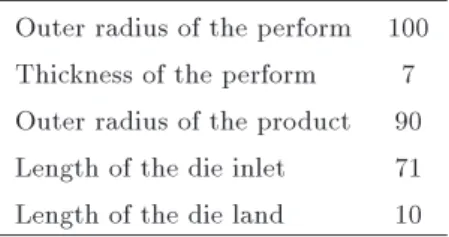
A penalty formulation was used to model the friction in the contact surfaces. The limiting shear stress was obtained by m=p3, where m = 0:15 is the friction coecient commonly used for cold forging conditions [7]. The tube and die geometry is presented in Table 1.
3. The slab method analysis
Lahoti and Altan [7] were the rst to model the radial forging process by the slab method of analysis. Ghaei
Figure 2. The maximum axial stress in the tube for dierent number of elements.
Figure 3. The computational mesh used in this study used for tube.
Table 1. Tube and die geometry (mm). Outer radius of the perform 100 Thickness of the perform 7 Outer radius of the product 90 Length of the die inlet 71 Length of the die land 10
et al. [5] considered linear and circular (convex, concave and hybrid) proles for the die inlet zone, and studied the eects of die shape on the deformation pattern and quality of radially forged products using the slab method analysis. In these studies, the analyses were restricted to special die proles, namely, linear and circular, However, here, a generalized slab method analysis is presented that is capable of modeling the radial forging process with virtually any curved shape die prole.
As shown in Figure 4, two distinct regions of
Figure 4. Dierent deformation zones in the radial forging process.
deformation exist in the radial forging process without a mandrel: (I) sinking zone, and (II) sizing zone.
The following assumptions are made for the slab method analysis:
1. The tube thickness remains constant throughout the process;
2. Friction at the die-tube interface produces a con-stant friction shear stress;
3. The normal stress acting on the slab does not vary over the cross-section and it is also a principle stress;
4. The slab is free from shear stresses;
5. The material is rigid-perfectly plastic. 3.1. The sinking zone
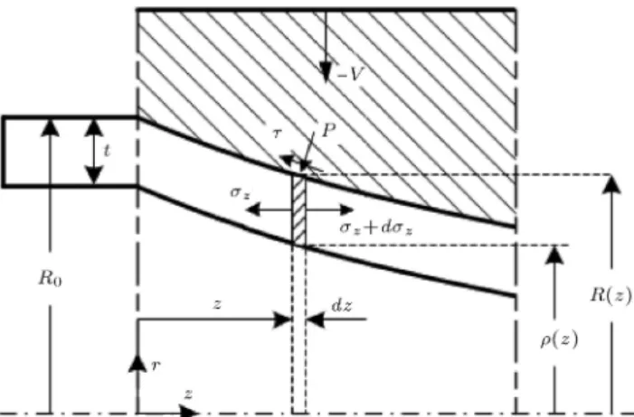
Figure 5 shows the stresses acting on an element of material in the sinking zone for radial forging with a die with a general curved-shape prole. In order for the element to be in equilibrium, we must have:
(z+ dz)(Az+ dAz) zAz pArsin
Arcos = 0; (1)
where p and are the radial pressure and shear stress due to friction, respectively.
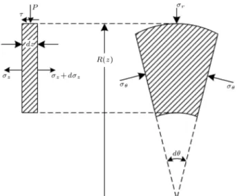
The following geometrical relations can be de-duced from Figure 6:
Az= [R2(z) 2(z)] ) dAz
= [2R(z)R0(z)dz 2(z)0(z)dz];
Ar= 2R(z)cos dz : (2)
The `0' symbol in this equation represents the rst
derivative with respect to z. Substituting Eq. (2) into Eq. (1) yields:
Figure 5. Stresses acting on an element in the sinking zone.
Figure 6. Free body diagram of an element in the sinking zone.
z 2[R(z)R0(z)dz (z)0(z)dz] + dz
[R2(z) 2(z)] p2R(z) dz
cos
sin
2R(z)cos dz
cos = 0; (3) which can be simplied to:
2z[R(z)R0(z)dz (z)0(z)dz]+dz[R2(z) 2(z)]
2pR(z) tan dz 2R(z)dz = 0: (4) Also, from the geometry in Figure 5, we can write:
tan = R0(z): (5)
This reduces Eq. (4) to: dz
dz =
2z[R(z)R0(z) (z)0(z)] 2pR(z)R0(z)+2R(z)
[R2(z) 2(z)] :
(6) Next, we consider the equilibrium of the element in the radial direction to obtain (see Figure 6):
r
=
R(z) (z)
R(z) : (7)
In the sinking region, the radial pressure on the die is small compared with the principal longitudinal and cir-cumferential stresses, and, therefore, the approximate yield condition is given by:
z = : (8)
Considering the boundary condition at the interface of the die and the tube, the following relationship is
obtained:
r= p R0(z): (9)
Solving Eqs. (7), (8) and (9) for p1 yields:
p = ( z)R(z) (z)R(z) R0(z): (10)
Substituting p from Eq. (10) into Eq. (6) gives: dz
dz =
2z(z)[0(z) R0(z)]
[R2(z) 2(z)]
2R0(z)[R(z) (z)]
[R2(z) 2(z)]
+2[R(z) + R(z)R02(z)]
[R2(z) 2(z)] : (11)
Using the reasonable assumption that the inner prole of the tube, (z), is parallel to its outer prole, R(z), we will have:
R0(z) = 0(z): (12)
Substituting Eq. (12) into Eq. (11) gives: dz
dz =
2R0(z)[R(z) (z)]
[R2(z) 2(z)]
+2[R(z) + R(z)R02(z)]
[R2(z) 2(z)] : (13)
In the analysis of the radial forging process, it is normally assumed that the frictional shear stress varies according to the sticking condition [4-6]:
= mp
3: (14)
Applying this assumption to Eq. (13) leads to: dz
dz =
2R(z) [R2(z) 2(z)]
R0(z)[R(z) (z)]
R(z)
m[1 + R02(z)]
p 3
!
: (15)
This equation gives the variation of the axial stress, z,
in the sinking zone, with respect to the axial distance, z. Using the derivative chain rule, we can write:
dz
dR = 1 R0(z)
dz
dz : (16)
Therefore, the axial stress, z, variation along the
radial distance, R, is as follows: dz
dR =
2R R0[R2 2]
R0[R ]
R
m[1 + R02]
p 3
: (17)
Eq. (17) holds for a die that has a general curved shape prole. In the special case of a linear die with an inlet angle of , we have:
R0 = tan : (18)
Since the tube thickness, t0, is assumed constant in the
sinking zone, for a linear die, we can write: R = t0cos ;
R2 2= t
0cos (2R t0cos ): (19)
Substituting Eqs. (18) and (19) into Eq. (17) gives: dz
dR=
2R t0(2R t0cos )
t0
R m p
3 sin [1+tan2]
: (20) In most radial forging processes the inlet angle, , is generally less than 15. Thus, tan2 is much
smaller than unity and can be ignored in the tan2+1
expression. Accordingly, Eq. (20) can be written as: dz
dR =
2R t0(2R t0cos )
t0 R m p 3 sin ; (21)
which is the equation obtained previously by Lahoti and Altan in [7].
The radial pressure on the die surface is equal to the radial stress, r. Thus, the radial pressure in the
sinking zone is:
psinking= R(z)t0 ( z): (22)
3.2. The sizing zone
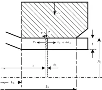
Considering the equilibrium of forces acting on an element in the sizing zone gives (see Figure 7):
Figure 7. Stresses acting on an element in the sizing zone.
(z+ dz z)(R22 (R2 t)2)
(2R2dz) = 0: (23)
Using Eq. (14) after some simplication gives: dz
dz 2 p
3
mR2
(2R2 t1)t1 = 0; L1 z L2:(24)
Integrating Eq. (24) yields: z= ze+p23(2RmR2
2 t1)t1(z ze); L1z L(25)2;
where z = ze at z = ze. When ze = L2, we have
ze= f, where f is the front pull per unit area, and,
when ze= L1, zeis the axial stress obtained from the
analysis of the sinking zone.
Next, we consider the equilibrium of the element in the radial direction to obtain (see Figure 8):
p = t
R2: (26)
The yield condition given by Eq. (8) is also satised in the sizing zone, thus, the radial pressure in the sizing zone is:
pSizing =( R z)t
2 : (27)
4. Results
4.1. Comparison of nite element and slab method results
The obtained slab method equations were numerically solved using an algorithm based on the Runge-Kutta scheme. The slab method and nite element results for the radial pressure distribution are compared in Figure 9 for a linear die with inlet angle of 8.
Figure 8. Free body diagram of an element in the sizing zone.
Figure 9. Comparison of slab method and FEM results.
The dierence between the nite element and slab method results can be attributed to the changes in the radial pressure along the thickness of the tube, which was assumed to be constant in the slab method analysis [6].
4.2. Eect of the die prole shape on the product quality
In order to study the eect of die prole shape on product quality, three dierent proles were considered for the die, namely, linear, quadratic and cubic order proles, as shown in Figures 10, 11 and 12, respectively. In the case of curved shape dies, it is recom-mended to use a prole the slope of which changes gradually to zero (equal to the slope of the sizing zone) at the end of the sinking zone to achieve a more
Figure 10. Die with linear prole.
Figure 11. Die with quadratic (2nd order) prole.
homogenous structure in the product [6]. Therefore, the two employed curved proles are chosen to satisfy this recommendation.
The residual stress distribution was selected as the measure of product quality, since it is an indication of the degree of deformation homogeneity. In other words, the more homogenous is the deformation the smaller is the residual stress [5]. Especially, the hoop and axial residual stress distribution in the inner surface of the tube is of great importance. Namely, tensile hoop and axial residual stresses may lead to the opening of cracks, which accelerates the failing of the tube, while compressive stresses close the cracks and increase the tube life. Moreover, these stresses have a fundamental eect on the dimensional stability, wear resistance and fatigue life of the tube and are treated as one of the most important parameters of surface quality.
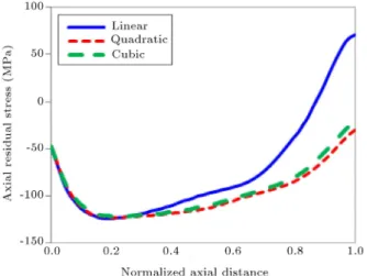
The hoop and axial residual stress distribution in the inner surface of the product are shown in Figures 13 and 14, respectively.
Figure 13. The axial residual stress distribution in the inner surface of the workpiece.
Figure 14. The hoop residual stress distribution in the inner surface of the workpiece.
It is evident that both axial and hoop stresses are more favorable (compressive) in the product forged by the curved-prole dies, while the value of the unfavorable tensile residual stress is very high when forging by a linear die. Also, it can be seen that the residual stress distributions are very close together for the quadratic and cubic dies. But, the residual stress distribution of the linear die departs from that of the curved dies near the die outlet. This stems from the fact that the slope of the curved-prole dies gradually changes to zero (equal to the slope of the sizing zone) at the end of the sinking zone. Gradual and uniform change of the die slope produces a uniform deformation in the workpiece and leads to an improved residual stress distribution.
However, the slope change from the sinking to the sizing zone happens sharply in the linear-prole die, which leads to a less uniform deformation and, consequently, a less desirable stress distribution. As Figure 14 shows, the maximum value of the tensile residual stress occurs very close to the point of this slope change. The equivalent plastic strain, the residual von-Mises stress and the residual hoop stress distributions in the tube forged by the linear die are presented in Figures 15, 16 and 17, respectively. 4.3. Eect of the die prole shape on the
forging force
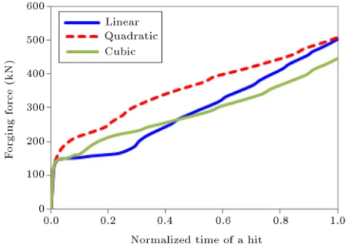
Figure 18 shows the variation of the forging force during a single stroke of the die, i.e. one hit of the die on the workpiece. As this gure illustrates, the quadratic die demands the highest forging force, while the cubic die requires the lowest. The cubic die has a concave prole in the inlet, which gradually changes to
Figure 15. The equivalent plastic strain distribution in the workpiece.
Figure 16. The von-Mises stress distribution in the workpiece (Pa).
Figure 17. The hoop stress distribution in the workpiece (Pa).
Figure 18. The forging force variation during a die hit on the workpiece.
a convex prole in the outlet. This leads to gradual deformation of the workpiece in dierent die strokes and, consequently, low forging force requirement in the cubic prole die.
5. Conclusions
In this paper, the nite element method was employed to study the eect of die prole shape on a radial forging process without a mandrel. A novel slab method analysis was developed for verication of the FEM model. This novel method is capable of modeling the radial forging process without a mandrel with virtually any curved shape die prole. The nite element and slab method results show good agreement. The results of this study can be summarized as follows:
1. Comparison of the residual axial and hoop stress distribution in the inner surface of tubes forged by dierent dies showed that:
- Tensile residual stresses develop in the tube forged by the linear-prole die, which is unfa-vorable;
- Favorable (compressive) residual stresses develop in tubes forged by dies with quadratic (convex)
and cubic (with concave inlet and convex outlet) proles;
2. The simulations predicted that the die with a cubic prole requires the lowest forging force. This will reduce the energy requirement of the radial forging process and leads to longer die and machine life;
3. Since both the residual stress distribution and the forging force are favorable for the cubic die prole, it is recommended for the radial forging of tubes without a mandrel.
References
1. Sanjari, M., Saidi, P., Taheri, A.K. and Hossein-Zadeh, M. \Determination of strain eld and heterogeneity in radial forging of tube using nite element method and microhardness test", Materials and Design, 38(1), pp. 147-153 (2012).
2. Ghaei, A., Movahhedy, M.R. and Taheri, A.K. \Finite element modelling simulation of radial forging of tubes without mandrel", Materials and Design, 29(1), pp. 867-872 (2008).
3. Sahoo, A.K., Tiwari, M.K. and Mileham, A.R. \Six sigma based approach to optimize radial forging op-eration variables", Journal of Materials Processing Technology, 202(2), pp. 125-136 (2008).
4. GFM Precision Forging Machine, GFM technical lit-erature (October 1976).
5. Ghaei, A. and Movahhedy, M.R. \Die design for the radial forging process using 3D FEM", Journal of Materials Processing Technology, 182(1), pp. 534-539 (2007).
6. Ghaei, A., Movahhedy, M.R. and Taheri, A.K. \Study of the eects of die geometry on deformation in the ra-dial forging process", Journal of Materials Processing Technology, 170(1), pp. 156-163 (2005).
7. Lahoti, G.D. and Altan, T. \Analysis of the radial forging process for manufacturing of rods and tubes", Journal of Engineering for Industry, 98(1), pp. 265-271 (1976).
Biography
Hamed Afrasiab received his BS, MS and PhD degrees in Mechanical Engineering from Sharif Uni-versity of Technology, Iran, in 2004, 2006 and 2011, respectively. He is currently Professor in the Depart-ment of Mechanical Engineering at Babol University of Technology, Iran. His main research interests are nite element simulation of solid, uid and uid-structure interaction problems, stress-strain analysis, and modeling of metal forming processes.