Sharif University of Technology
Scientia IranicaTransactions D: Computer Science & Engineering and Electrical Engineering www.scientiairanica.com
Optimization of magnetic devices using Surface Current
Method (SCM)
M. Arehpanahi
and E. Hesam
Department of Electrical Engineering, Tafresh University, Tafresh, P.O. Box 79611-39518, Iran. Received 20 September 2013; received in revised form 27 October 2015; accepted 18 April 2016
KEYWORDS Optimization; Surface current method;
Electric magnet and nite element method.
Abstract. In this paper, application of the Surface Current Method (SCM) in analysis and optimization of electromechanical devices is proposed. SCM is one of the numerical techniques in electromagnetic eld analysis. In SCM, only magnetic boundaries are subdivided against Finite Element Method (FEM) which is subdivided into all of domains; therefore, the calculation resources of SCM are much lower than FEM. SCM with low-calculation resource is one of the best numerical techniques for magnetic devices' optimization. In this paper, using SCM, three electromechanical systems have been optimized based on minimization of weight per force. Verication of simulation results is done by FEM.
© 2017 Sharif University of Technology. All rights reserved.
1. Introduction
Recently, designers have been dealing with the opti-mization of electromagnetic devices such as levitation devices, electric machines, electric magnet, and trans-formers [1-3]. The commercial numerical method based on Finite Element Method (FEM) is a powerful tool for magnetic eld analysis, but it cannot sometimes be used eortlessly in this task, especially if several geo-metric parameters are involved, and the combination of several constraints has to be taken into account. In this situation, because of high-calculation resources and a large number of iterations, the time consumption will be high enough, and so FEM would not be suitable for pre-elementary or optimization process. The Surface Current Method (SCM) is a candidate one for this ap-plication in magnetic optimization, especially in power engineering eld [4-6]. Because of easy management of the geometric conguration and simplied interface with external procedures, SCM can be used for such
*. Corresponding author. Tel.: +98-086-36227430
E-mail address: [email protected] (M. Arehpanahi)
a purpose. SCM calculates the magnetic ux density using suitable distributions of surface currents on the magnetic boundaries with dierent homogeneous permeability models; therefore, magnetic boundaries can be replaced by suitable distribution of nite surface currents. Therefore, Biot-savart law can be used to simply compute magnetic ux density. After this replacement, magnetic ux density at any points of domain is obtained by summation of magnetic ux den-sity due to the current sources and surface currents on the boundaries. The main advantages of the SCM are: - Applicability to any magnetic boundary shape, rect-angular or circular cross-section current sources with any axes orientation and to generally shaped perma-nent magnets;
- Accuracy and calculation resources are comparable with those of the commercial FEM codes;
- User-friendly interface with fast input-output oper-ations, conguration preview;
interface with external procedures to perform para-metric analyses such as optimization processes; - The ability to express movement or rotation by
shape functions simply using constant mesh congu-ration in dynamic analysis of electrical machines [7]. In 2D analysis, SCM elements are line shapes (one dimension), but in FEM, mesh shapes are two-dimensional such as triangles. This method was initially developed to consider linear magnetic materials; its application was indeed limited because it required a suitable surface current distribution on the magnetic discontinuities. Analysis of rotating single-phase reluctance motor with constant speed using SCM was carried out and compared with FEM [7]. Coupling between electric and magnetic circuits using SCM was developed in a linear dynamic analysis of the electromechanical system (relay structure) without any moving object [8]. Dynamic analysis of Switched Reluctance Motor (SRM) with asymmetric half-bridge converter using SCM is proposed in [9]. The combined method for mesh renement in SCM is proposed in [10]. The lack of SCM is analysis of the magnetic devices with variable permeability (saturation eect). In [6], two methods of considering saturation eect have been reported, but these techniques are not general and do not present a unique and complete inside object subdivision method for permeability calculation. In other words, none of the two techniques has not presented general identifying roles to select inside sampling points. To overcome this diculty, an automated sampling points selection for saturation modeling in SCM is presented [11]. In this paper, optimization of the magnetic devices using SCM is
proposed. The three case studies for optimization are analyzed and compared with the FEM.
2. Optimization using SCM 2.1. SCM principle
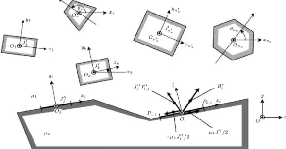
The principle of SCM is based on replacing the mag-netic boundaries in dierent material interfaces using suitable distribution of nite surface currents. Let us consider the presence of ns current sources and one
closed interface between two regions with two cases of permeability 1 and 2 (Figure 1). The current
sources consist of n0
s rectangular conductors carrying
uniform current density, J0
k (k = 1; 2; ; n0s), and
ns n0s permanent magnet with polygonal contour
represented by suitable distribution of surface current on their boundaries. The boundary between two regions with dierent uniform permeability models consists of closed polygonal contour with ne sides; the
lth generic side (l = 1; 2; ; ; ne) is subdivided into
nl segments. The magnetic discontinuity is replaced
by uniform permeability, 1, and an unknown uniform
linear current density, J00
i, on the ith segment with 2di
(i = 1; 2; ; nb; nb = ne P
l=1nl) length. The magnetic
ux density of ith surface current due to the jth surface current is expressed in Eq. (1):
B00
i;j=iJj001e
i[arg(Pb;j Pa;j) arg(Pb;i Pa;i)]
2 log
P Pa;j
P Pb;j
= J00
j:fi;j00(p); (1)
where f00
i;j(p) and pa;i, pb;i are shape function and
vectors, respectively, which identify the beginning and ending of ith element.
The unknown surface currents are computed by imposing the validation of the tangential magnetic ux density refraction law on each element of magnetic in-terface [6], expressed in Eq. (2). Eq. (2) can be written in nb-order matrix which is expressed in Eq. (3):
Re[Bs i(p)] +
nb X
j=1 i6=j
J00
jRe(fij00(p)) + 1;iJ 00 i
2
=2;i
1;i 8 > > < > > :Re[B s i(p)]+ nb X j=1 i6=j J00
jRe[fi;j00 (p)] 1;iJ 00 i 2 9 > > = > > ;(2); [M]: [J00] = [Bs
x] : (3)
Here, [Bs
x] is tangential to magnetic ux density matrix
due to the current sources, and [M] is SCM stiness matrix that only depends on the boundaries geometry, expressed in Eq. (4). For a magneto-static eld problem with dierent values of the current sources, this matrix should be calculated only once, because it is independent of the current source values. According to the global coordinate point in fx; yg plane as p = x + iy:
[M] = 2 6 6 4 1;1
2 2;12;1+1;11;1 real(f
00 1;nb)
... ... ...
real(f00
nb;1)
1;nb
2 2;nb2;nb+1;nb1;nb
3 7 7 5 ;
(4) where 1;i and 2;i are inner and outer cases of
permeability on ith element. 2.2. Optimization procedure
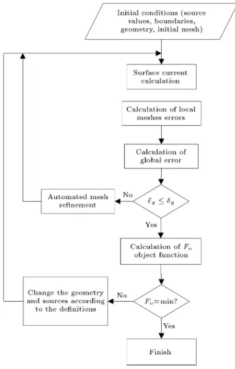
The general optimization process in SCM is similar to FEM optimization, but the SCM's calculation re-sources are very fewer than those of FEM; therefore, for a large number of iterative processes in design or pre-elementary design procedure, the time consumption of the SCM is much lesser than that of FEM, which is in contrast to SCM against FEM. The exibility of the geometry variation during iterative procedure and fast post-processing computation are the main advantages of SCM in comparison with FEM. The optimization process in SCM is illustrated in Figure 2.
The owchart description is as follows:
1. The initial conditions, such as boundaries geom-etry and current sources values and positions are dened;
2. The surface current on the boundaries is calculated using Eq. (3);
3. The local mes error is dened in Eq. (5):
Figure 2. Optimization process using SCM.
"i=
Z Pb;i
Pa;i
jJ(p)j djpj; Ji(p) = Ji
2 1;i
2;i 1;i
2;i+1;iRe
0 B B @Bis(p)+
n
X
j=1 j6=i
f00 i;j(p)Jj00
1 C C A :
(5) 4. The global error is expressed in Eq. (6):
h"i =
n
P
i=1"ijPb;i Pa;ij n
P
k=1jPb;k Pa;kj
; and:
~" =s h"i
n
P
i=1jPb;i Pa;ij n
P
k=1J
002
k jPb;k Pa;kj
: (6)
5. If ~" g (g is pre-dened minima), then objective
6. If ~" > g, the automated mesh renement process
is started to decrease the global error value; 7. If Fo is to be minimized, the optimization process
will be nished;
8. If Fo is not minimized, the geometry and current
source values are rened according to the limita-tions dened for dimensions' variation, and then back to Step 2, i.e. surface current calculation part in Figure 2.
3. Description of procedure and simulation results
In this section, three case studies are analyzed with SCM and compared with the FEM. The rst case study is an electric magnet, shown in Figure 3. The optimization process is applied to the main part, which is called \iron body" in Figure 3. Minimization of main part weight per accessible force is dened as objective function \Fo.". The force which is applied
to the xed yoke (Figure 3) is dependent on the core and coil dimension; therefore, it can dene one optimization parameter (combination of weight and force together) instead of two parameters. Moreover, the time consumption of this denition will absolutely be lower than that of the two-parameter optimization process. The objective function, i.e. main part weight per applied force, is expressed in Eq. (7):
Fo, WFt
y; (7)
where Wt is the total weight of main part, and Fy
is the applied force to the xed yoke. For a simple modeling of saturation during optimization process, the value of the magnetic ux density at the center of air gap is limited to Bav 0:4 T . The initial
design data and their limitations are listed in Table 1. The relative permeability of core is 4000. Variation of the coil and core dimension during optimization process is proportional to the weight of coil and core,
Figure 3. The initial design of electric magnet.
Table 1. Initial design data and limitations of the rst case study.
Jc= 4 A/mm2 hc= 70 mm
cu= 8933 kg/mm3 fe= 7870 kg/mm3
ag = 5 mm ha= 80 mm
Wa;min= 40 mm Wi;max= 110 mm
Wa;min= 40 mm Wa;max= 170 mm
Wc;min= 10 mm Wc;max= 70 mm
respectively. Because the volume of core is higher than coil; therefore, the increment of core volume during optimization process for achieving the minimum weight must be lower than coil increment. The constant parameters in optimization process are coil height, air gap, height, and weight of iron body. For obtaining the uniform magnetic ux density in the iron body, the increment of core dimension (Wi and Wa) during
the optimization process is dened as uniform. The height of coils is considered constant. Therefore, only coil width (Wc) is changed during optimization process.
The outer side of the iron body (Wy) is considered
constant, then the inner side of core (Wa) decreases
while contact between coil and core occurs (Wc =
Wa). For thermal limitation, the current density of
coil is considered constant (Jc = 4 A/mm2 ). The
minimization algorithm, which is used in this paper, is Genetic Algorithm (GA). The initial values of the electric magnet parameters, shown in Figure 3, are:
Wa= 100 mm; Wi= 50 mm; Wc = 16 mm;
Wy= 250 mm; ag = 5 mm; hy= 25 mm;
ha = 80 mm; hc= 70 mm:
In Figure 3, all parameters which are placed in the box can be changed, and others are constant during optimization process. The optimized design of electric magnet using GA is illustrated in Figure 4. The total
Figure 4. The optimized design of electric magnet (all dimensions are in mm).
weights in initial and optimized designs are 11.32 kg and 26 kg (230% increment), respectively; therefore, the objective function is changed from 10.68 to 0.9329, which is illustrated in Figure 5 in all iterations. The applied force to the xed yoke during optimization process is illustrated in Figure 6, where DFy =
Fy(SCM) Fy(FEM). It demonstrates that initial force is
1.05 kN/mdue to initial value selection at the rst step of optimization process, but at the end of the process, it is convergent to 27.5 kN/m, which is 27 times larger than the initial design value, which is very good.
The good agreement between SCM and FEM results is shown in Figure 6. The variation of iron body and coil dimension (Wi, Wa, and Wc) at any iteration
is illustrated in Figure 7. The inner side of core (Wa)
Figure 5. The objective function convergence.
Figure 6. The comparison of the calculated force via SCM and FEM.
Figure 7. Variation of the rst case study dimension.
at the beginning of optimization process is higher than other core dimensions, but at the end of optimization steps, it is to be lower than Wi. The coil dimension, Wc,
has low variation during optimization process excluding the rst steps. The comparison of the SCM and FEM elements numbers is illustrated in Figure 8. It is clear that the number of SCM elements per iteration is very fewer than that of FEM (70% lesser). The number of elements per iteration is a well factor for comparison of calculation resource.
The second case study is an electric magnet with permanent magnet, shown in Figure 9. The P M which is used in this structure is a NdFeBr (Br= 1:1 T and
Hc = 880 kA/m). The initial values of dimension
are:
Wa= 50 mm; Wi= 50 mm; Wpm= 70 mm;
Wc= 15 mm; ag = 5 mm; hi = 120 mm;
hy= 25 mm; Wy = 250 mm:
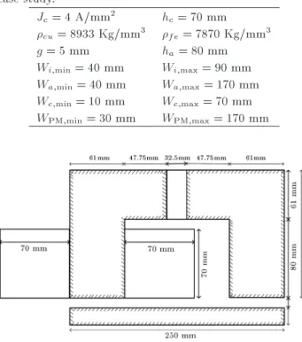
The box parameters are illustrated in Figure 9, and they can be changed during the optimization process. All limitations and information are listed in Table 2. The objective function of the second case study is the same as that of the rst case study.
Figure 8. Comparison of SCM and FEM elements number.
Table 2. Initial design data and limitations of the second case study.
Jc= 4 A/mm2 hc= 70 mm
cu= 8933 Kg/mm3 fe= 7870 Kg/mm3
g = 5 mm ha= 80 mm
Wi;min= 40 mm Wi;max= 90 mm
Wa;min= 40 mm Wa;max= 170 mm
Wc;min= 10 mm Wc;max= 70 mm
WPM;min= 30 mm WPM;max= 170 mm
Figure 10. Optimized second case study using GA.
Figure 11. Optimized second case study using DSA.
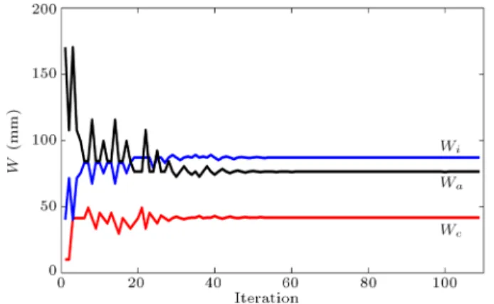
The optimized designs of the second case study using GA and (Direct Search Algorithm) DSA are illustrated in Figures 10 and 11, respectively. The convergence of the two optimization methods (GA and DSA) is shown in Figure 12. The convergence of two methods occurs at 51 iterations; the time consumption of the GA is almost three times of DSA, while DSA cannot always nd global minimum; therefore, GA optimization results are accepted for the nal design optimization. The variation of the copper, core, and PM weights is illustrated in Figure 13. According to the Figure 13, it is clear that the PM weight (Wpm) has
a minimum variation because of high magnetic energy production related to others. Consequently, the PM width is a highly eective parameter in optimization related to other parameters. Wt, in Figure 13, shows
the total weight of electric magnet parts dened as
Figure 12. Objective function convergence.
Figure 13. The variation of the copper, core, PM, and total weights.
Figure 14. Force convergence using SCM and FEM.
variable parameters previously, i.e. iron body, coil, and P M weights. The force calculated by SCM, FEM, and their dierence between them (DF ) are shown in Figure 14. According to Figure 14, the force which is obtained by SCM has been veried by FEM very well because of low value of DF in all iterations. The number of elements is used by SCM and FEM for calculation of the force illustrated in Figure 15. The number of elements used by FEM and SCM at the nal step is 5500 and 900 elements, respectively. It is demonstrated that the number of SCM elements per iteration is very fewer than FEM.
perma-Figure 15. Number SCM and FEM elements.
nent magnet step motor, which is illustrated in Fig-ure 16(a) [6]. The relative permeability of stator is 4000, and the rotor is made of a cylindrical permanent magnet with rec= 0 and Hc = 820 kA/m.
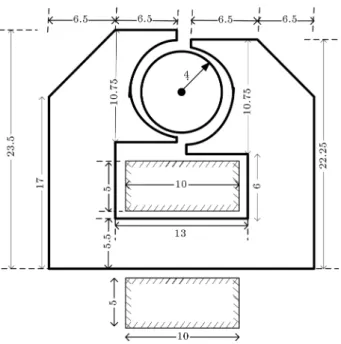
is position of magnetic vector of rotor. The box parameters, illustrated in Figure 16(b), can be changed during optimization process. All limitations and parameters are listed in Table 3. The objective function of single-phase step motor is the same as the rst case study. The initial force applied to the rotor is 0.63 kN/m, and the total weight of motor is 0.26 kg. The optimized output results using GA are listed in Table 4. According to Table 4, the optimized structure of single-phase step motor is illustrated in Figure 17. In the optimized design, the applied force is increased twice, i.e. 1.12 kN/m, and the total weight of motor is decreased by 0.22 kg, which is a satisfactory result. The number of SCM and FEM elements is 269 and 610, respectively. The optimized force which is calculated by SCM is 1.16 kN/m that is veried by FEM.
Table 3. Parameter and limitation of the third case study. Jc= 4 A/mm2 hc= 5 mm
jcu= 8933 kg/m3 jfe= 7870 kg/m3
H = 10:75 mm r = 4 mm Wi;min= 5 mm Wi;max= 12 mm
Wi1;min= 4 mm Wi1;max= 11 mm
Wc;min= 4 mm Wc;max= 12 mm
hi;min= 15:5 mm hi;max= 22:5 mm
hi1;min= 22 mm hi1;max= 29 mm
hi2;min= 20:75 mm hi2;max= 27:75 mm
icoil= 240 A = 90
r;iron= 4000 r;PM= 1
Table 4. Optimized output of the third case study using GA.
icoil= 208:04 A W c = 10:5 mm
Wi= 6:5 mm Wi1= 5:5 mm
hi1= 23:5 mm hi2= 22:25 mm
nSCM= 269 hi= 17 mm
Wt= 0:22 kg Ft= 1:2 kN/m
4. Conclusion
In this paper, application of Surface Current Method (SCM) in optimization of magnetic devices is pro-posed. Because of low calculation resource of SCM in optimization process and post-processing related to the FEM, this technique is ideal for pre-elementary design and optimization of magnetic devices. The implementation of the SCM for analysis of the variable
Figure 17. Optimized conguration of the third case study (all dimensions are in mm).
parameter is very simple, and it requires low calculation resources. Here, three case studies have been optimized using SCM and FEM. In all three case studies, the number of elements per iteration of SCM is much fewer than FEM that it demonstrates that the calculation resources of SCM are much fewer than those of FEM in iterative process such as optimization. Verication of SCM results is done by FEM. Consequently, SCM is a fast and accurate method for optimization procedure of the electromagnetic devices.
References
1. Di Barba, P., Mognaschi, M.E., Palka, R., Paplicki, P. and Szkolny, S. \Design optimization of a permanent-magnet excited synchronous machine for electrical au-tomobiles", International Journal of Applied Electro-magnetics and Mechanics, 39(1), pp. 889-895 (2012). 2. Chunyan, L., Chunhong, L. and Zhongxian, W.
\Fi-nite element method simulation and comparison of a segmented-PM motor and a whole-PM motor", Journal of Computers, 9(9), pp. 2058-2065 (2014). 3. Rochepault, E., Aubert, G. and Vedrine, P.
\Three-dimensional magnetic optimization of accelerator mag-nets using an analytic strip model", Journal of Applied Physics, 116(2), p. 23910-23910 (2014).
4. Semidey, S.A. and Mayor, J.R. \Design and optimiza-tion of SMPM electric machines incorporating direct winding heat exchange", Power Electronics, Machines and Drives, pp. 1-6 (2014).
5. Andriollo, M., Bolognese, L. and Tortella, A. \Au-tomated contour renement procedure for the 2D magnetic eld analysis by the surface-current method", In 9th Conf. on Electromagnetic Field Computation (2000).
6. Andriollo, M., Martinelli, G. and Tortella, M. \Appli-cation of the surface-current method to the analysis of saturated electromagnetic devices", The Interna-tional Journal for Computation and Mathematics in Electrical and Electronic Engineering, 23(1), pp. 328-347 (2004).
7. Arehpanahi, M. and Milimonfared, J. \Analysis of rotating magnetic devices by surface current method", CEFC2006 (2006).
8. Arehpanahi, M. and Milimonfared, J. \Electrical and magnetic circuit coupling using surface current method", IEMDC 2007 (2007).
9. Arehpanahi, M. and Milimonfared, J. \Dynamic anal-ysis of switched reluctance motor with asymmetric half-bridge converter using surface current method (SCM)", International Journal of Applied Electromag-netics and Mechanics, 31(4), pp. 1383-5416 (2009). 10. Arehpanahi, M. and Saberi Jamal, N. \A modied
mesh renement mesh procedure for 2D magnetic eld analysis using surface current method", International Journal of Applied Electromagnetics and Mechanics, 49(3), pp. 337-345 (2015).
11. Arehpanahi, M. and Namdar, R. \Automated sam-pling point renement procedure for 2-D high sat-urated magnetic eld analysis by surface current method", International Journal of Applied Electromag-netics and Mechanics, 46(3), pp. 675-681 (2014).
Biographies
Mehdi Arehpanahi was born in Kermanshah, Iran, in 1978. He received his BS degree from Tabriz Univer-sity in 2000, and MS and PhD degrees from Amirkabir University of Technology, Tehran, Iran, in 2003 and 2009, respectively. He is currently an Assistant Profes-sor in the Electrical Engineering Department of Tafresh University, Iran. His research interests include work on computational electromagnetics and electrical machine design and drives.
Ebrahim Hessam was born in Qazvin, Iran, in 1986. He obtained his BS degree from Yazd University, Yazd, Iran, in 2008, and MS degree in Electrical Engineering (Power Systems) in 2011 from Tafresh University, Iran. He is currently teaching in the Ghiaseddin Jamshid Kashani University of Abeyek, Iran.