Reference number
STANDARD
2531
Sixth edition 2009-12-15
Ductile iron pipes, fittings, accessories
and their joints for water applications
Tuyaux, raccords et accessoires en fonte ductile et leurs assemblages pour l'eau
PDF disclaimer
This PDF file may contain embedded typefaces. In accordance with Adobe’s licensing policy, this file may be printed or viewed but shall not be edited unless the typefaces which are embedded are licensed to and installed on the computer performing the editing. In downloading this file, parties accept therein the responsibility of not infringing Adobe’s licensing policy. The ISO Central Secretariat accepts no liability in this area.
Adobe is a trademark of Adobe Systems Incorporated.
Details of the software products used to create this PDF file can be found in the General Info relative to the file; the PDF-creation parameters were optimized for printing. Every care has been taken to ensure that the file is suitable for use by ISO member bodies. In the unlikely event that a problem relating to it is found, please inform the Central Secretariat at the address given below.
COPYRIGHT PROTECTED DOCUMENT
© ISO 2009All rights reserved. Unless otherwise specified, no part of this publication may be reproduced or utilized in any form or by any means, electronic or mechanical, including photocopying and microfilm, without permission in writing from either ISO at the address below or ISO’s member body in the country of the requester.
ISO copyright office
Case postale 56 • CH-1211 Geneva 20 Tel. + 41 22 749 01 11
Fax + 41 22 749 09 47 E-mail copyright@iso.org Web www.iso.org Published in Switzerland
Contents
PageForeword ...iv
1 Scope ...1
2 Normative references...1
3 Terms and definitions ...2
4 Technical requirements ...5
4.1 General ...5
4.2 Pressure classification and dimensional requirements...7
4.3 Material characteristics...11
4.4 Coating and linings for pipes...12
4.5 Coatings and linings for fittings and accessories ...13
4.6 Marking ...13
5 Leaktightness requirements...13
5.1 Pipes and fittings...13
5.2 Flexible joints...13
5.3 Flanged joints as cast, screwed, welded and adjustable...15
6 Test methods ...17
6.1 Dimensions ...17
6.2 Straightness of pipes ...17
6.3 Tensile test ...17
6.4 Brinell hardness ...19
6.5 Works leaktightness test of pipes and fittings...20
7 Type tests ...20
7.1 Leaktightness of joints to internal pressure...20
7.2 Leaktightness of joints to external pressure...21
7.3 Leaktightness of joints to negative internal pressure...22
7.4 Leaktightness and mechanical resistance of flanged joints ...22
8 Tables of dimensions...23
8.1 Socket and spigot pipes ...23
8.2 Flanged pipes ...25
8.3 Fittings for socketed joints...25
8.4 Fittings for flanged joints ...41
Annex A (informative) External protection ...59
Annex B (informative) Internal protection ...60
Annex C (informative) Dimensions of preferred pressure classes and other pressure class pipes ...61
Annex D (normative) Pipe wall thicknesses, stiffness and diametral deflection ...63
Annex E (normative) Quality assurance...71
Annex F (informative) Safety factors ...72
Foreword
ISO (the International Organization for Standardization) is a worldwide federation of national standards bodies (ISO member bodies). The work of preparing International Standards is normally carried out through ISO technical committees. Each member body interested in a subject for which a technical committee has been established has the right to be represented on that committee. International organizations, governmental and non-governmental, in liaison with ISO, also take part in the work. ISO collaborates closely with the International Electrotechnical Commission (IEC) on all matters of electrotechnical standardization.
International Standards are drafted in accordance with the rules given in the ISO/IEC Directives, Part 2. The main task of technical committees is to prepare International Standards. Draft International Standards adopted by the technical committees are circulated to the member bodies for voting. Publication as an International Standard requires approval by at least 75 % of the member bodies casting a vote.
Attention is drawn to the possibility that some of the elements of this document may be the subject of patent rights. ISO shall not be held responsible for identifying any or all such patent rights.
ISO 2531 was prepared by Technical Committee ISO/TC 5, Ferrous metal pipes and metallic fittings, Subcommittee SC 2, Cast iron pipes, fittings and their joints.
This sixth edition cancels and replaces the fifth edition (ISO 2531:1998), of which it constitutes a technical revision. A new classification system for pipes and fittings based on pressure is introduced with minimum wall thickness determined by allowable operating pressure.
Ductile iron pipes, fittings, accessories and their joints for
water applications
1 Scope
This International Standard specifies the requirements and test methods applicable to ductile iron pipes, fittings, accessories and their joints for the construction of pipelines:
⎯ to convey water (e.g. for human consumption and raw water), ⎯ operated with or without pressure, and
⎯ installed below or above ground.
NOTE In this International Standard, all pressures are relative pressures expressed in bar 1).
This International Standard specifies materials, dimensions and tolerances, mechanical properties and standard coatings of pipes, fittings and accessories. It also gives performance requirements for all components including joints.
This International Standard applies to pipes, fittings and accessories cast by any type of foundry process or manufactured by fabrication of cast components, as well as corresponding joints in the size range DN 40 to DN 2600 inclusive.
It is applicable to pipes, fittings and accessories which are
⎯ manufactured with socketed, flanged or spigot ends (joint design and gasket shapes are outside the scope of this International Standard),
⎯ normally delivered internally and externally coated.
Pipes and fittings are classified according to allowable operating pressure.
2 Normative
references
The following referenced documents are indispensable for the application of this document. For dated references, only the edition cited applies. For undated references, the latest edition of the referenced document (including any amendments) applies.
ISO 4016, Hexagon head bolts — Product grade C
ISO 4034, Hexagon nuts — Product grade C
ISO 4633, Rubber seals — Joint rings for water supply, drainage and sewerage pipelines — Specification for materials
ISO 6506-1, Metallic materials — Brinell hardness test -– Part 1: Test method
ISO 7005-2, Metallic flanges — Part 2: Cast iron flanges
ISO 7091, Plain washers — Normal series — Product grade C
ISO 10803, Design method for ductile iron pipes
ISO 10804, Restrained joint systems for ductile iron pipelines — Design rules and type testing
EN 1092-2, Flanges and their joints — Circular flanges for pipes, valves, fittings and accessories, PN designated — Part 2: Cast iron flanges
3 Terms and definitions
For the purposes of this document, the following terms and definitions apply. 3.1
accessory
any casting other than a pipe or fitting, which is used in a pipeline EXAMPLE 1 Glands and bolts for mechanical flexible joints (see 3.18).
EXAMPLE 2 Glands, bolts and locking rings or segments for restrained joints (see 3.24). NOTE The term accessory is not relevant for valves or hydrants of any type.
3.2
allowable operating pressure PFA
maximum internal pressure, excluding surge, which a component can safely withstand in permanent service 3.3
allowable site test pressure PEA
maximum hydrostatic pressure that a newly installed component can withstand for a relatively short duration, when either fixed above ground level or laid and backfilled underground, in order to measure the integrity and tightness of the pipeline
NOTE This test pressure is different from the system test pressure, which is related to the design pressure of the pipeline.
3.4 batch
quantity of castings from which a sample may be taken for testing purposes during manufacture 3.5
component
any product defined as an element of a pipe, fitting or accessory See 3.1, 3.9 and 3.22.
3.6 deviation
amount by which the design length may differ from the standardized length of a pipe or a fitting
NOTE Pipes and fittings are designed to a length selected in the range of standard length plus or minus the deviation (see Table 6); they are manufactured to this length plus or minus the tolerance given in Table 7.
3.7
diametral stiffness of a pipe
3.8
ductile iron
type of cast iron used for pipes, fittings and accessories in which graphite is present primarily in spheroidal form
3.9 fitting
casting other than a pipe, which allows pipeline deviation, change of direction or bore NOTE Flanged sockets, flanged spigots and collars are also classified as fittings.
3.10 flange
end of a pipe or fitting, extending perpendicular to its axis, with bolt holes equally spaced in a circle
NOTE A flange can be fixed (e.g. integrally cast, screwed-on or welded-on) or adjustable. An adjustable flange comprises a ring, in one or several parts bolted together, which bears on an end joint hub and which can be freely rotated around the barrel axis before jointing.
3.11
flanged joint
joint between two flanged ends 3.12
flexible joint
joint providing significant angular deflection and movement parallel and/or perpendicular to the pipe axis 3.13
gasket
sealing component of a joint 3.14
hoop stress
σ
stress in a pipe or fitting under pressure, acting tangentially to the perimeter of a transverse section 3.15
joint
connection between the ends of pipes and/or fittings in which a gasket is used to effect a seal 3.16
laying length Le
length by which a pipeline progresses when an additional pipe is installed
NOTE 1 For socket and spigot pipes, it is equal to the total length of the pipe, Ltot, minus the maximum spigot insertion depth, Li, as given by the manufacturer and as shown in Figure 4. For flanged pipes, it is equal to the total length of the pipe.
NOTE 2 It is expressed in metres. 3.17
maximum allowable operating pressure PMA
maximum internal pressure, including surge, which a component can safely withstand in service 3.18
mechanical flexible joint
3.19
nominal pressure PN
numerical designation, which is a convenient rounded number, used for reference purposes
NOTE 1 All components of the same nominal size, DN, designated by the same PN number have compatible mating dimensions.
NOTE 2 Adapted from ISO 7268. 3.20
nominal size DN
alphanumeric designation of size for components of a pipework system, which is used for reference purposes NOTE 1 It comprises the letters DN followed by a dimensionless whole number, which is indirectly related to the physical size, in millimetres, of the bore or outside diameter of the end connections.
NOTE 2 Adapted from ISO 6708:1995, definition 2.1. 3.21
ovality
out-of-roundness of a pipe section, equal to Equation (1)
(
)
(
11 22)
100 A A A A − + (1) whereA1 is the maximum axis, in millimetres; A2 is the minimum axis, in millimetres. 3.22
pipe
casting of uniform bore, with straight axis, having either socket, spigot or flanged ends
NOTE This does not apply to flanged sockets, flanged spigots and collars, which are classified as fittings. 3.23
push-in flexible joint
flexible joint assembled by pushing the spigot through the gasket into the socket of the mating component 3.24
restrained joint
joint in which a means is provided to prevent separation of the assembled joint 3.25
socket
female end of a pipe or fitting to make the connection with the spigot of the next component 3.26
spigot
3.27 spigot end
maximum insertion depth of the spigot, Li, plus 50 mm See Li in Figure 4.
3.28
standardized length
length of pipe barrel and fitting body or branch as defined in this International Standard
NOTE 1 For socket and spigot pipes, and fittings, it is designated Lu (lu for branches). For flanged pipes, and fittings, it is designated L (l for branches). See Figures 4 to 27.
NOTE 2 For flanged pipes and fittings, the standardized length L (l for branches) is equal to the total length. For socketed pipes and fittings, the standardized length Lu (lu for branches) is equal to the total length minus the spigot
insertion depth, as indicated in the manufacturer’s catalogues. 3.29
type test
proof-of-design test, which is done once and is repeated only after change of design
4 Technical
requirements
4.1 General
4.1.1 Pipes and fittings
Thicknesses, lengths and coatings are specified in this subclause, 4.2.3, 4.2.4 and 4.4 for pipes, and 4.5 for fittings. When, by agreement between the manufacturer and the purchaser, pipes and fittings with different lengths, thicknesses and/or coatings, and other types of fittings than those given in 8.3 and 8.4, are supplied in accordance with this International Standard, they shall comply with all the other requirements of this International Standard. This includes pipe and fittings manufactured to national standards and regulations. The standard nominal sizes, DN, of pipes and fittings are the following:
40, 50, 60, 65, 80, 100, 125, 150, 200, 250, 300, 350, 400, 450, 500, 600, 700, 800, 900, 1000, 1100, 1200, 1400, 1500, 1600, 1800, 2000, 2200, 2400 and 2600.
The stiffness and allowable diametral deflection of ductile iron pipes are as given in Annex D.
NOTE When installed and operated under the conditions for which they are designed (see Annexes A and B), ductile iron pipes, fittings, accessories and their joints maintain all their functional characteristics over their operating life, due to constant material properties, to the stability of their cross-section and to their design with high safety factors.
4.1.2 Surface condition and repairs
Pipes, fittings and accessories shall be free from defects and surface imperfections which could impair their compliance with the requirements of Clauses 4 and 5.
When necessary, pipes and fittings may be repaired, for example by welding, to remove surface imperfections and localized defects which do not affect the entire wall thickness, provided that the repaired pipes and fittings comply with all the requirements of Clauses 4 and 5.
4.1.3 Types of joints and interconnection 4.1.3.1 General
Joint design and gasket shapes are beyond the scope of this International Standard.
Rubber gasket materials shall conform to the requirements of ISO 4633 for water applications. When materials other than rubber are necessary (e.g. high-temperature flanged joints), they shall conform to the appropriate International Standards.
4.1.3.2 Flanged joints
Flanged joints shall be designed to facilitate attachment to flanges whose dimensions and tolerances comply with ISO 7005-2 or EN 1092-2. This ensures interconnection between all flanged components (pipes, fittings, valves, etc.) of the same DN and PN and adequate joint performance. Bolts and nuts shall comply, as a minimum, with the requirements of ISO 4016 and ISO 4034, property class 4.6. Where washers are required, they shall comply with ISO 7091.
In addition, each type of flange joint shall be designed to meet the performance requirements of 5.3.
Although it does not affect interconnection, the manufacturer shall indicate in his handbook whether his products are normally delivered with fixed flanges or loose flanges.
4.1.3.3 Flexible joints
Pipes and fittings with flexible joints shall be in accordance with 4.2.2.1 for their spigot external diameters, DE, and their tolerances. This provides the possibility of interconnection between components equipped with different types of flexible joints. In addition, each type of flexible joint shall be designed to meet the performance requirements of 5.2.
For interconnection with certain types of joints operating within a tighter tolerance range on DE, the manufacturer’s guidance should be followed as to the means of ensuring adequate joint performance up to the highest pressures (e.g. measurement and selection of external diameter).
For interconnection with existing pipelines which can have external diameters not in accordance with 4.2.2.1, the manufacturer’s guidance should be followed as to the appropriate means of interconnection (e.g. adaptors).
4.1.3.4 Restrained joints
Restrained joints for ductile iron pipelines shall be designed in accordance with ISO 10804. Their spigot external diameters, DE, and their tolerances shall comply with 4.2.2.1.
4.1.4 Materials in contact with water intended for human consumption
When used under the conditions for which they are designed, in permanent or in temporary contact with water intended for human consumption, ductile iron pipes, fittings and their joints shall not have detrimental effects on the properties of that water for its intended use.
Ductile iron pipeline systems, including pipes, fittings, accessories and joints, consist of various materials. When used for conveying water intended for human consumption, the materials in contact with the water shall meet the relevant requirements of the national standards or regulations in the country of use with respect to effect on water quality.
4.2 Pressure classification and dimensional requirements
4.2.1 Pressure classifications4.2.1.1 General
Components with flexible joints shall be classified by the allowable operating pressure (PFA) in bar, prefixed by the letter C.
Components with flanged joints shall be classified by the PN number of the flange. Allowable component pressure relationships shall be the following:
a) Allowable operating pressure (PFA) = C, in bar
b) Allowable maximum operating pressure (PMA) = 1,20 × PFA, in bar c) Allowable site test pressure (PEA) = (1,20 × PFA) + 5, in bar
The allowable pressures within a pipeline system shall be limited to the lowest pressure classification of all components within the system.
4.2.1.2 Preferred pressure classes
Preferred pressure classes of components with flexible joints are C25, C30, and C40. Other pressure classes are allowable, including C20, C50, C64 and C100.
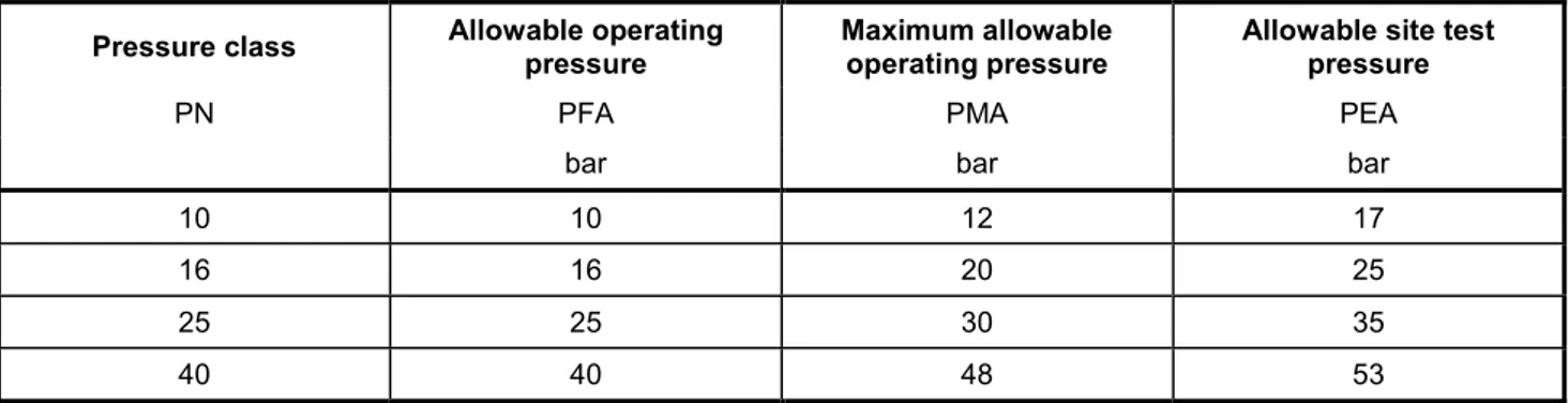
Pressure classes for components with flanged joints are PN10, PN16, PN25 and PN40. 4.2.1.3 Allowable pressures
Allowable pressures of components are as given in Tables 1 and 2.
Table 1 — Allowable pressures of components with flexible joints for preferred classes
Pressure class Allowable operating pressure Maximum allowable operating pressure Allowable site test pressure
C PFA PMA PEA
bar bar bar
25 25 30 35 30 30 36 41 40 40 48 53
Table 2 — Allowable pressures of components with flanged joints
Pressure class Allowable operating pressure Maximum allowable operating pressure Allowable site test pressure
PN PFA PMA PEA
bar bar bar
10 10 12 17 16 16 20 25 25 25 30 35 40 40 48 53
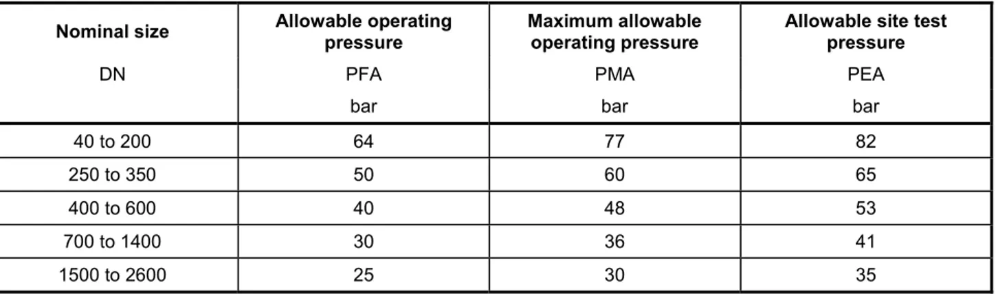
The allowable pressure for fittings as specified in Tables 15 to 33 are as follows: ⎯ socketed fittings, except tees, are given in Table 3;
⎯ socketed tees may be less than those given in Table 3 and shall be given in the manufacturer’s handbook;
⎯ all flanged fittings and fittings with one flange, such as double-socketed tees with flanged branch, flanged spigots and flanged sockets, are limited by the flange PN and are given in Table 2.
Table 3 — Allowable pressures for socketed fittings
Nominal size Allowable operating pressure Maximum allowable operating pressure Allowable site test pressure
DN PFA PMA PEA
bar bar bar
40 to 200 64 77 82
250 to 350 50 60 65
400 to 600 40 48 53
700 to 1400 30 36 41
1500 to 2600 25 30 35
Appropriate limitations shall be taken into account, which can prevent the full range of these pressures being used in an installed pipeline. For example, operation at the PFA values can be limited by the lower pressure capability of other pipeline components, e.g. flanged pipework, certain types of tees and specific designs of flexible joints. When other limitations exist due to the joint type or to any specific design arrangement, they shall be given in the manufacturer’s handbook.
4.2.2 Diameter
4.2.2.1 External diameter
Table 14 gives the values of the external diameter, DE, of the spigot end of pipes and fittings, when measured circumferentially using a circumferential tape as specified in 6.1.1. The positive tolerance is + 1 mm and applies to all pressure classes of pipes and also to flanged spigot fittings.
The negative tolerance depends on the design of each type of joint and shall be as specified in national standards, or, when not so specified, in manufacturers’ handbooks, for the type of joint and the nominal size considered.
In addition, the ovality (see 3.21) of the spigot end of pipes and fittings shall ⎯ remain within the tolerances of DE for DN 40 to 200, and
⎯ not exceed 1 % of DE for DN 250 to DN 600 or 2 % for DN > DN 600.
The manufacturer’s recommendations should be followed with respect to the necessity and means of ovality correction; certain types of flexible joints can accept the maximum ovality without the need for spigot re-rounding prior to jointing.
4.2.2.2 Internal diameter
The nominal values of the internal diameters of centrifugally cast pipes, expressed in millimetres, are approximately equal to the numbers indicating their nominal sizes, DN.
4.2.3 Wall thickness
4.2.3.1 Pipes with flexible joints
The minimum wall thickness for pipes, emin, shall be not less than 3,0 mm and shall be determined using Equation (2): min m PFA SF DE 20 (PFA SF) e R × × = + × (2) where
emin is the minimum pipe wall thickness, in millimetres; PFA is the allowable operating pressure, in bar; SF is the safety factor for PFA (= 3);
DE is the nominal pipe external diameter (see Table 14), in millimetres;
Rm is the minimum tensile strength of ductile iron, in megapascals (Rm = 420 MPa; see Table 8). NOTE Equation (2) is derived from Barlow’s equation, i.e. hoop stress, σ = PD/2t (see 3.14)
For pipes centrifugally cast, the minimum wall thickness, emin, shall not be less than 3,0 mm. The nominal wall thickness, enom, is equal to the minimum wall thickness, emin, plus (1,3 + 0,001 DN).
For pipes not centrifugally cast, the minimum wall thickness, emin, shall not be less than 4,7 mm. The nominal wall thickness, enom, is equal to the minimum wall thickness, emin, plus (2,3 + 0,001 DN).
For centrifugally cast pipes, nominal pipe wall thicknesses for preferred ductile iron pressure classes are given in Table 14. For other pressure classes, as given in Annex C, the user should confirm the availability with the manufacturer.
4.2.3.2 Flanged pipes
Flanged pipe shall be classified by PN number. The pressure class of the barrel of the flanged pipes shall be equal to or greater than a value in bar equal to the PN of the flanges. The pressure class of the flanged pipe barrel to be used for fabricated flanged pipe shall be as indicated in 8.2 for welded-on flanges, screwed-on flanges and integrally cast flanges.
NOTE Pipe threads are regarded as loss of wall thickness. 4.2.3.3 Fittings
Nominal wall thicknesses, enom, are given for fittings in Tables 15 to 29, with allowable pressures given in 4.2.1.3. The minimum wall thickness, emin, for fittings is: emin = enom− (2,3 + 0,001 DN).
Fittings with other pressure classifications are allowed. The manufacturer shall be responsible for the design of the fittings including the determination of wall thickness. The minimum wall thickness, emin, shall be not less than 3,0 mm.
The design shall be carried out by a calculation method, e.g. finite element analysis, or an experimental method, e.g. hydrostatic testing, using a safety factor of 3 against failure with respect to PFA.
4.2.4 Length
4.2.4.1 Socket and spigot pipes
Pipes shall be supplied to the lengths given in Table 4.
Table 4 — Standardized lengths of socket and spigot pipe
Dimensions in metres DN Standardized lengths, Lu a 40 and 50 3 60 to 600 4 or 5 or 5,5 or 6 or 9 700 and 800 4 or 5,5 or 6 or 7 or 9 900 to 2600 4 or 5 or 5,5 or 6 or 7 or 8,15 or 9 NOTE Not all the standardized lengths are available in all countries.
a See 3.28.
The manufacturers’ design lengths, Lu (see 3.28), shall be within a deviation (see 3.6) of ± 250 mm with respect to the lengths given in Table 4 and shall be given in their handbooks. The actual length, Lu, shall be measured according to 6.1.3 and shall not differ from the manufacturer’s design length by more than the tolerance given in Table 7. Of the total number of socket and spigot pipes to be supplied in each diameter, the percentage of shorter pipes shall not exceed 10 %.
NOTE 1 Pipes cut for test purposes can be excluded from the 10 % limitation and treated as full-length pipes.
NOTE 2 When pipes are ordered on a meterage basis, the manufacturer can determine the required quantity of pipes to be supplied by the summation of the measured individual pipe laying lengths.
4.2.4.2 Flanged pipes
The lengths of flanged pipes shall be as given in Table 5. Other lengths are available by agreement between the manufacturer and the purchaser.
Table 5 — Standardized lengths of flanged pipe
Dimensions in metres
Type of pipe DN Standardized lengths,La
With cast-on flanges 40 to 2600 0,5 or 1 or 2 or 3 or 4
40 to 500 2 or 3 or 4 or 5
600 to 1000 2 or 3 or 4 or 5 or 6 With screwed-on or welded-on flanges
1100 to 2600 4 or 5 or 6 or 7
a See 3.28.
4.2.4.3 Fittings
Fittings shall be supplied in the lengths given in 8.3 and 8.4 except that, alternatively, socket fittings may be supplied in the lengths of the national standard of the country of manufacture.
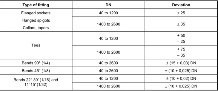
The permissible deviations (see 3.6) on the lengths of series A fittings shall be as given in Table 6.
Table 6 — Permissible deviations on length of fittings
Dimensions in millimetres
Type of fitting DN Deviation
40 to 1200 ± 25 Flanged sockets Flanged spigots Collars, tapers 1400 to 2600 ± 35 40 to 1200 + 50 − 25 Tees 1400 to 2600 + 75 − 35 Bends 90° (1/4) 40 to 2600 ± (15 + 0,03) DN Bends 45° (1/8) 40 to 2600 ± (10 + 0,025) DN 40 to 1200 ± (10 + 0,02) DN Bends 22° 30' (1/16) and 11°15' (1/32) 1400 to 2600 ± (10 + 0,025) DN 4.2.4.4 Tolerances on lengths
The tolerances on lengths shall be as given in Table 7.
Table 7 — Tolerances on length
Dimensions in millimetres
Type of casting Tolerance
Socket and spigot pipes (full length or shortened) −+3070
Fittings for socketed joints ± 20
Pipes and fittings for flanged joints ± 10 a
a By agreement between manufacturer and purchaser, smaller tolerances are possible, but not less than ± 3 mm for DN u 600 and ± 4 mm for DN > 600.
4.2.5 Straightness of pipes
Pipes shall be straight, with a maximum deviation of 0,125 % of their length.
The verification of this requirement is normally carried out by visual inspection, but in case of doubt or in dispute, the deviation shall be measured in accordance with 6.2.
4.3 Material
characteristics
4.3.1 Tensile propertiesDuring the manufacturing process the manufacturer shall carry out suitable tests to verify these tensile properties; these tests may be either
a) a batch sampling system whereby samples are obtained from the pipe spigot or, for fittings, from samples cast separately or integrally with the casting concerned (test bars shall be machined from these samples and tensile tested according to 6.3), or
b) a system of process control testing (e.g. non-destructive), by which a positive correlation can be demonstrated with the tensile properties specified in Table 8; testing verification procedures shall be based on the use of comparitor samples having known and verifiable properties; this system of testing shall be supported by tensile testing in accordance with 6.3.
Table 8 — Tensile properties
Minimum tensile strength,
Rm MPa
Minimum percent elongation after fracture,
A %
Type of casting
DN 40 to DN 2600 DN 40 to DN 1000 DN 1100 to DN 2600
Pipes centrifugally cast 420 10 7
Pipes not centrifugally cast,
fittings and accessories 420 5 5
By agreement between the manufacturer and the purchaser, the 0,2 % proof stress, Rp02, may be measured. It shall be not less than: 270 MPa when AW 12 % for DN 40 to DN 1000 or when AW 10 % for DN > 1000; 300 MPa in other cases. For centrifugally cast pipes of DN 40 to DN 1000 having a design minimum wall thickness of 10 mm or greater, the minimum elongation after fracture shall be 7 %.
4.3.2 Brinell hardness
The hardness of the various components shall be such that they can be cut, tapped, drilled and/or machined with standard tools. In case of dispute, the hardness shall be measured according to 6.4.
The Brinell hardness shall not exceed 230 HBW for centrifugally cast pipes and 250 HBW for non-centrifugally cast pipes, fittings and accessories. For components manufactured by welding, a higher Brinell hardness is allowed in the heat-affected zone of the weld.
4.4 Coating and linings for pipes
Pipes shall normally be delivered internally and externally coated. 4.4.1 External coatings
Ductile iron pipeline systems can be installed in a wide range of external operating environments. These environments can be characterized according to their aggressivity. For relevant factors, see A.1.
Coatings specified by relevant International Standards are available as specified in A.2. Other coatings are available.
4.4.2 Internal linings
Ductile iron pipeline systems can be used to convey a wide range of raw waters and potable waters. These internal environments can be characterized by their aggressivity. Relevant factors to be considered for cement mortar linings without seal coats are given in B.1.
Linings specified by relevant International Standards are available as specified in B.2. Other linings are also available.
4.5 Coatings and linings for fittings and accessories
Fittings and accessories shall normally be delivered internally and externally coated. 4.5.1 External coatings
Ductile iron pipeline systems can be installed in a wide range of external operating environments. These environments can be characterized by their aggressivity. For relevant factors, see A.1.
Coatings specified by relevant International Standards are available as specified in A.3. Other coatings are also available.
4.5.2 Internal linings
Ductile iron pipeline systems can be used to convey a wide range of raw waters and potable waters. These internal environments can be characterized according to their aggressivity. Relevant factors to be considered for cement mortar linings without seal coats are given in B.1.
Linings specified by relevant International Standards are available as specified in B.3. Other linings are also available.
4.6 Marking
All pipes and fittings shall be durably and legibly marked and shall bear at least the following indications: a) a reference to this International Standard, i.e. ISO 2531;
b) the manufacturer’s name or mark; c) identification of the year of manufacture; d) identification as ductile iron;
e) the DN;
f) the PN rating of flanges, if applicable;
g) the C pressure class of socket and spigot pipe.
Items b) to f) shall be cast-on or cold stamped. Items a) and g) can be applied by any method, e.g. painted on the castings.
5 Leaktightness
requirements
5.1 Pipes
and
fittings
Pipes and fittings shall be designed to be leaktight at their allowable site test pressure (PEA). They shall be tested according to 6.5 and shall exhibit no visible leakage, sweating or any other sign of failure.
5.2 Flexible
joints
5.2.1 GeneralAll flexible joints for ductile iron pipes and components shall be designed in compliance with the requirements of 5.2. If the design has been tested and documented by the manufacturer and successfully used for a
in 5.2.3 for external pressure and as specified in 5.2.4 for negative internal pressure, is only required for significant changes in design which could adversely affect the performance of the joint.
Joint designs shall be type tested to demonstrate leaktightness to both internal and external pressure under the most unfavourable conditions of castings tolerances and joint movements.
There shall be a type test for at least one DN for each of the groupings given in Table 9. One DN is representative of a grouping when the performances are based on the same design parameters throughout the size range.
Table 9 — DN groupings for type tests
DN groupings 40 to 250 300 to 600 700 to 1000 1100 to 2000 2200 to 2600
Preferred DN in each grouping 200 400 800 1600 2400
If a grouping covers products of different designs and/or manufactured by different processes, the grouping shall be sub-divided.
If, for a manufacturer, a grouping contains only one DN or PN, this DN or PN may be considered as part of the adjacent grouping provided that it is of identical design and manufactured by the same process.
The type tests shall be carried out in the configuration of maximum design radial gap between the components to be jointed (smallest spigot together with largest socket).
In the type test, the maximum gap shall be equal to the maximum design radial gap with a tolerance of −05%. The internal socket diameter may be machined to achieve this, even if the resulting diameter is slightly outside the normal manufacturing tolerance.
All joints shall be performance tested with a spigot having an average iron wall thickness (over a distance of 2 DN, in millimetres, from the spigot face) equal to the specified minimum value for the pipe for which the joint is designed, +100 %. It is permissible to machine the spigot of the pipe bore to achieve the required thickness.
Restrained flexible joints shall be designed and tested in accordance with ISO 10804. 5.2.2 Internal pressure
The leaktightness of joints to internal pressure shall be type tested as specified in 7.1 at a test pressure of 1,5PFA + 5 bar; the joints shall exhibit no visible leakage in the two following positions:
a) joint aligned and subjected to shear; the shear force across the joint, expressed in N, shall not be less than 30 times DN;
b) joint deflected; the test angular deflection shall be the maximum allowable deflection indicated in the manufacturer's handbook, but not less than 3° 30' for DN 40 to DN 300, 2° 30' for DN 350 to DN 600, 1° 30' for DN 700 to DN 2600. These minimum deflections do not apply to restrained joint pipe.
5.2.3 External pressure
The leaktightness of joints to external pressure shall be type tested as specified in 7.2; the joints shall exhibit no visible leakage when subjected to a shear load, expressed in newtons, not less than 30 times DN.
5.2.4 Negative internal pressure
The leaktightness of joints to negative internal pressure shall be type tested as specified in 7.3 at a test pressure of 0,9 bar below atmospheric pressure (approximately 0,1 bar absolute pressure). The maximum pressure change during the test period shall not be more than 0,09 bar after 2 h, when tested in the following two positions:
a) joint aligned and subjected to shear; the shear force across the joint, expressed in N, shall not be less than 30 times DN;
b) joint deflected; the test angular deflection shall be the maximum allowable deflection indicated in the manufacturer’s handbook, but not less than 3° 30' for DN 40 to DN 300, 2° 30' for DN 350 to DN 600, 1° 30' for DN 700 to DN 2600. These minimum deflections do not apply to restrained joint pipe.
5.3 Flanged joints as cast, screwed, welded and adjustable
5.3.1 GeneralAll flanged joints for ductile iron pipes and components shall be designed in compliance with the requirements of 5.3. If the design has been tested and documented by the manufacturer and successfully used for a minimum of 10 years, the performance of a type test as specified in 5.3.2 is only required for significant changes in design which could adversely affect the performance of the joint.
When flanges are involved, there shall be a type test for at least one DN for each of the groupings given in Table 9. The PN to be tested is the highest PN existing for each flange design. One PN is representative of a grouping when the performances are based on the same design parameters throughout the size range. If a grouping covers products of different designs and/or manufactured by different processes, the grouping shall be sub-divided.
If, for a manufacturer, a grouping contains only one DN or PN, this DN or PN may be considered as part of the adjacent grouping provided that it is of identical design and manufactured by the same process.
5.3.2 Internal pressure and bending moment
In order to demonstrate their strength and leaktightness in service conditions, flanged joints shall be subjected to a type test. When tested as specified in 7.4, they shall show no visible leakage under the combined effects of a hydrostatic internal pressure and a bending moment as given in Table 10, where
⎯ the pressure is (1,5PN + 5) bar,
⎯ the relevant bending moment is obtained by addition of the bending moments due to the weight of the components and of the water in the test assembly and those due to a possible external load calculated as a function of the length of the unsupported span of the testing arrangement (see 7.4).
A type test shall be carried out on each type of flange joint available from the manufacturer in accordance with Table 10.
The bending moments given in Table 10 are approximately equal to those resulting from the weight of the preferred classes of pipes (utilizing the nominal thicknesses), of the cement mortar lining, and of the water over an unsupported pipe length, L, between simple supports, with, for welded, integrally cast and adjustable flanged joints,
⎯ L = 8 m for DN u 250, ⎯ L = 12 m for DN W 300;
and for screwed flanged joints, ⎯ L = 6,8 m for DN u 800, ⎯ L = 10 m for DN W 900.
Table 10 — Bending moments for flange joint type tests of preferred classes of pipes
Integrally cast, welded
and adjustable Screwed
DN kN·m kN·m 40 0,6 0,4 50 0,7 0,6 60 0,9 0,7 65 1,0 0,8 80 1,3 1,0 100 1,7 1,4 125 2,4 2,0 150 3,1 2,7 200 4,8 4,5 250 7,1 6,7 300 22,1 9,3 350 29,1 12,6 400 36 16 450 45 20 500 54 25 600 77 35 700 100 47 800 129 52 900 161 140 1000 197 159 1100 237 192 1200 281 214 1400 383 274 1500 437 314 1600 495 355 1800 623 447 2000 766 549 2200 928 644 2400 1 100 764 2600 1 287 894
6 Test
methods
6.1 Dimensions
6.1.1 External diameterPipes with sockets and spigot ends shall be measured at their spigot by means of a circumferential tape for compliance with the outer diameter tolerance. They can also be verified by means of pass-fail gauges.
In addition, the pipes shall be visually inspected at their spigot for compliance with the ovality tolerance and, in case of doubt, checked by measurement of the maximum and minimum axes. This control may also be carried out by pass-fail gauges.
The frequency of testing is related to the system of production and the quality control used by the manufacturer.
6.1.2 Wall thickness
Pipe wall thickness compliance shall be demonstrated by the manufacturer; a combination of various means may be used, such as:
⎯ pipe weight control;
⎯ direct wall thickness measuring or gauging by suitable equipment, such as mechanical or ultrasonic equipment. The frequency of testing is related to the system of production and quality control used by the manufacturer.
6.1.3 Length
The length of centrifugally cast pipes with sockets and spigot ends shall be measured by means of suitable equipment
⎯ on the first pipe cast from a new mold, for full length pipes, and
⎯ on the first cut pipe, for pipes which are systematically cut to a predetermined length.
6.2 Straightness of pipes
The pipe shall be rolled on two supports or rotated along its axis on rollers, which in each case are separated by at least two thirds of the standard pipe length.
The point of maximum deviation from the true axis shall be determined, and the deviation measured at that point shall not exceed the limit fixed in 4.2.5.
6.3 Tensile
test
6.3.1 SamplingThe thickness of the sample and the diameter of the test bar shall be as indicated in Table 11. 6.3.1.1 Centrifugally cast pipes
A sample shall be cut from the spigot of the pipe. This sample may be cut perpendicular to, or parallel with, the pipe axis, but in case of dispute the parallel-to-axis sample shall be used.
6.3.1.2 Pipes not cast centrifugally, fittings and accessories
Samples shall be taken, at the manufacturer’s discretion, either from an integrally cast sample, from a sample attached to the casting, or from a sample cast separately. In the latter case, it shall be cast from the same metal as that used for the casting. If the casting is subjected to heat treatment, the sample shall be subjected to the same heat treatment.
6.3.2 Test bar
A test bar shall be machined from each sample to be representative of the metal at the mid-thickness of the sample, with a cylindrical part having the diameters given in Table 11. If the specified diameter of the test bar is greater than 60 % of the measured minimum thickness of the sample, it is allowed to machine a test bar with a smaller diameter, or to cut another sample in a thicker part of the pipe. Other test bar shapes, complying with International Standards or national standards are permitted.
The test bars shall have a gauge length at least five times the nominal test bar diameter. The ends of the test bars shall be such that they will fit the testing machine.
The surface roughness of the machined gauge length of the test bar shall be such that Rzu 6,3 µm. Two methods of measuring the tensile strength may be used at the manufacturer’s discretion: Method A:
Produce the test bar to a nominal diameter ± 10 %, measure the actual diameter before the test with an accuracy of ± 0,01 mm and use this measured diameter to calculate the cross-sectional area and the tensile strength; or
Method B:
Produce the test bar to a nominal area, So, within a specified tolerance on the diameter (see Table 11) and use the nominal area to calculate the tensile strength.
Table 11 — Dimensions of test bar
Test bar method A Test bar method B Nominal diameter Nominal area So Nominal diameter Tolerance on diameter Type of casting mm mm2 mm mm
Centrifugally cast pipes with wall thickness:
⎯ less than 6 mm 2,5 5 2,52 ± 0,01
⎯ 6 mm up to but not including 8 mm 3,5 10 3,57 ± 0,02
⎯ 8 mm up to but not including 12 mm 5 20 5,05 ± 0,02
⎯ 12 mm and over 6 30 6,18 ± 0,03
Pipes, fittings and accessories not cast centrifugally:
⎯ integrally cast samples 5 20 5,05 ± 0,02
⎯ separately cast samples: 5 20 5,05 ± 0,02
⎯ thickness 12,5 mm for casting thickness
less than 12 mm 6 30 6,18 ± 0,03
⎯ thickness 25 mm for casting thickness
6.3.3 Equipment and test method
The tensile testing machine shall have suitable holders or grips to attach to the test bar ends so as to positively apply the test load axially. The testing machine shall have a force range suitable for testing the bars to failure whilst indicating the load applied.
The rate of stressing shall be as constant as possible within the limits of 6 N/mm2 per second to 30 N/mm2 per second.
The tensile strength shall be calculated by dividing the maximum force sustained by the test bar by the cross-sectional area of the test bar before testing. The elongation shall be measured by piecing together the broken parts of the test bar and taking the ratio of the extended gauge length to the original gauge length. Alternatively, the elongation may be measured directly by means of an extensometer.
6.3.4 Test results
Test results shall comply with Table 8. If they do not comply, the manufacturer shall:
a) in the case where the metal does not achieve the required mechanical properties, investigate the reason and ensure that all castings in the batch are either re-heat-treated or rejected; castings which have been re-heat-treated are then re-tested as specified in 6.3;
b) in the case of a defect in the test bar, carry out a further test. If it passes, the batch is accepted; if not, the manufacturer has the option to proceed in accordance with a) above.
NOTE The manufacturer can limit the amount of rejection by making additional tests, in order of manufacture, until the rejected batch of castings is bracketed by a successful test at each end of the interval in question.
6.3.5 Test frequency
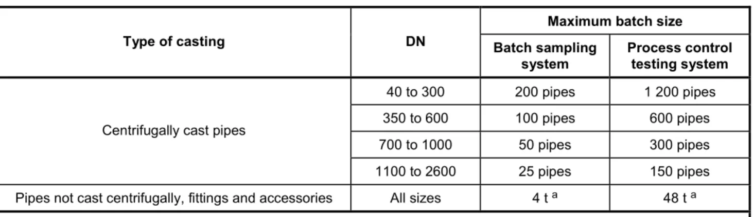
The frequency of testing is related to the system of production and quality control used by the manufacturer (see 4.3.1). The maximum batch sizes shall be as given in Table 12.
Table 12 — Maximum batch sizes for tensile testing
Maximum batch size
Type of casting DN Batch sampling
system Process control testing system 40 to 300 200 pipes 1 200 pipes 350 to 600 100 pipes 600 pipes 700 to 1000 50 pipes 300 pipes Centrifugally cast pipes
1100 to 2600 25 pipes 150 pipes
Pipes not cast centrifugally, fittings and accessories All sizes 4 t a 48 t a a Mass of crude castings, excluding risers.
6.4 Brinell
hardness
When Brinell hardness tests are carried out (see 4.3.2), they shall be performed either on the casting in dispute or on a sample cut from the casting. The surface to be tested shall be suitably prepared by slight local grinding, and the test shall be carried out in accordance with ISO 6506-1, using a ball of 2,5 mm or 5 mm or 10 mm diameter.
6.5 Works leaktightness test of pipes and fittings
6.5.1 GeneralPipes and fittings shall be tested as specified in 6.5.2 and 6.5.3, respectively. The test shall be carried out on all pipes and fittings before the application of their external and internal coatings, except for the metallic zinc coating of pipes which may be applied before the test.
The test apparatus shall be suitable for applying the specified test pressures to the pipes and/or fittings. It shall be equipped with an industrial pressure gauge with an error limit of ± 3 %.
6.5.2 Centrifugally cast pipes
The internal hydrostatic pressure shall be raised until it reaches the works hydrostatic test pressure equal to the pressure class and limited to the pressure of Preferred Classes. Higher pressures are permissible. The total duration of the pressure cycle shall be not less than 15 s, including 10 s at test pressure. Visual inspection shall be made during or immediately after the pressure test.
6.5.3 Pipes not cast centrifugally and fittings
At the discretion of the manufacturer, these pipes and fittings shall be submitted to a hydrostatic pressure test or an air test.
When the hydrostatic pressure test is carried out, it shall be done in the same way as for centrifugally cast pipes (see 6.5.2), except for the test pressures, which shall be as given in Table 13.
Table 13 — Works test pressure for pipes not cast centrifugally and fittings
DN Pipes not cast centrifugally and fittings
bar a
40 to 300 25 b
350 to 600 16
700 to 2600 10
a The works hydrostatic test pressure is less than for pipes because of the difficulty providing sufficient restraint to high internal pressure during testing.
b 16 bar for pipes and fittings with PN 10 flanges.
When the air test is carried out, it shall be with an internal pressure of at least 1 bar and a visual inspection time of not less than 10 s; for leak detection, the castings shall be either uniformly coated on the external surface by a suitable foaming agent or submerged in water.
7 Type
tests
7.1 Leaktightness of joints to internal pressure
This type test shall be carried out on an assembled joint comprising two pipe sections each at least 1 m long (see Figure 1).
The test apparatus shall be capable of providing suitable end restraints, whether the joint is in the aligned position, or deflected, or subjected to a shear load. It shall be equipped with a pressure gauge having an accuracy of ± 3 %.
The shear load, W, shall be applied to the spigot by means of a V-shaped block with an angle of 120°, located at approximately 0,5 × DN, in millimetres, or 200 mm from the socket face (whichever is the greater); the
socket shall bear on a flat support. The load, W, shall be such that the resultant shear force, F, across the joint is equal to the value specified in 5.2.2, taking into account the mass, M,of the pipe and its contents and the geometry of the test assembly, as given in Equation (3):
(
)
F c M c b W c a × − − = − (3) whereF is the resultant shear force across the joint, expressed in newtons; M is the mass of the pipe and its contents, expressed in newtons; W is the shear load, expressed in newtons;
a, b and c are given in Figure 1.
Figure 1 — Leaktightness of joints (internal pressure)
The test assembly shall be filled with water and suitably vented of air. The pressure shall be raised steadily until it reaches the test pressure given in 5.2.2; the rate of pressure increase shall not exceed 1 bar/s. The test pressure shall be kept constant within ± 0,5 bar for at least 2 h, during which the joint shall be thoroughly inspected every 15 min.
7.2 Leaktightness of joints to external pressure
This type test assembly, which applies only to push-in flexible joints, shall comprise two joints made with two pipe sockets connected together and one double-spigot piece so as to create an annular chamber allowing to test one joint under internal pressure and one joint under external pressure (see Figure 2).
The test assembly shall be subjected to the shear load defined in 5.2.3; one half of this load shall be applied to the spigot on each side of the test assembly, by means of a V-shaped block with an angle of 120°, located at approximately 0,5 × DN, in millimetres, or 200 mm from the end of sockets (whichever is the greater); the sockets shall bear on a flat support.
The test assembly shall then be filled with water and suitably vented of air. The pressure shall be steadily increased until it reaches the test pressure given in 5.2.3 and then kept constant within ± 0,1 bar for at least 2 h, during which the internal side of the joint subjected to external pressure shall be thoroughly inspected every 15 min.
7.3 Leaktightness of joints to negative internal pressure
The test assembly and test apparatus shall be as given in 7.1 with the pipe sections axially restrained to prevent them moving towards each other.
The test assembly shall be empty of water and shall be evacuated to a negative internal pressure of 0,9 bar (see 5.2.4) and then isolated from the vacuum pump. The test assembly shall be left under vacuum for at least 2 h during which the pressure shall not have changed by more than 0,09 bar. The test shall begin at a temperature between 5 °C and 40 °C. The temperature of the test assembly shall not vary by more than 10 °C for the duration of the test.
7.4 Leaktightness and mechanical resistance of flanged joints
The test assembly shall comprise pipes and/or fittings with identical flanges, assembled together by means of the gasket and bolts defined by the manufacturer. Both ends of the test assembly shall be equipped with blank flanges. The bolts shall be tightened to the torque defined by the manufacturer for the maximum PN of the DN under test. The bolt material grade, when not defined, shall comply as a minimum to property class 4.6 of ISO 4016.
The test assembly shall be placed on two simple supports (see Figure 3) such that the assembled flanged joint is positioned at mid span. The minimum length of unsupported span shall be either 6 DN, in millimetres, or 4 000 mm, whichever is the smaller. This length can be obtained by a combination of pipes or fittings, but only the tested joint at mid span shall be considered.
Figure 3 — Strength and leaktightness test for flanged joints
The test assembly shall be filled with water and suitably vented of air. The pressure shall be raised steadily until it reaches the test pressure given in 5.3. The external load, F, shall be applied to the assembled flanged joint by means of a flat plate, in a direction perpendicular to the axis of the test assembly, so as to cause the bending moment given in Table 10.
The internal pressure and the external load shall be kept constant for 2 h during which the flanged joint shall be thoroughly inspected.
CAUTION — All necessary safety precautions should be taken for the duration of the pressure test.
8 Tables of dimensions
8.1 Socket and spigot pipes
The dimensions of preferred pressure classes of socket and spigot pipes are as given in Figure 4 and Table 14. Wall thicknesses for preferred and other pressure classes of pipe are given in Annex C.
The values of Lu are given in Table 4. For external and internal coatings, see 4.4.
Key
DE nominal external diameter of spigot, in millimetres enom nominal wall thickness, in millimetres
L2 depth of socket, in metres Le = Ltot−Li laying length, in metres
Li maximum insertion depth as given by the manufacturer, in metres Ltot total length, in metres
Lu = Ltot−L2 standardized length, in metres
Table 14 — Preferred pipe pressure classes
DN DEa Pressure class Nominal iron wall thickness
enom mm mm mm 40 56 C40 4,4 50 66 C40 4,4 60 77 C40 4,4 65 82 C40 4,4 80 98 C40 4,4 100 118 C40 4,4 125 144 C40 4,5 150 170 C40 4,5 200 222 C40 4,7 250 274 C40 5,5 300 326 C40 6,2 350 378 C30 6,3 b 400 429 C30 6,5 b 450 480 C30 6,9 500 532 C30 7,5 600 635 C30 8,7 700 738 C25 8,8 b 800 842 C25 9,6 900 945 C25 10,6 1000 1048 C25 11,6 1100 1152 C25 12,6 1200 1255 C25 13,6 1400 1462 C25 15,7 1500 1565 C25 16,7 1600 1668 C25 17,7 1800 1875 C25 19,7 2000 2082 C25 21,8 2200 2288 C25 23,8 2400 2495 C25 25,8 2600 2702 C25 27,9
a A tolerance of +1 mm applies (see 4.2.2.1).
b Thicknesses are greater than calculated for “smoothing” between C40 and C30 and also between C30 and C25.
8.2 Flanged
pipes
A fundamental requirement for flanged pipework is its ability to support an external bending moment. The magnitude of these permissible bending moments is related to the weight of the pipe and its contents for a given span. Consequently, the manufacturer shall demonstrate by performance testing, as detailed in Clauses 5 and 7, the minimum thickness of pipe required for the different PN-rated flanges.
The values of L are given in Table 5. For coatings and linings, see 4.4.
Dimensions of flanges are in conformity with ISO 7005-2 and EN 1092-2 (see 4.1.3.2).
8.3 Fittings for socketed joints
In Tables 15 to 23, all the dimensions are nominal values and are given in millimetres. The values of Lu and lu have been rounded up to the nearest multiple of five.
For coating and linings, see 4.5. 8.3.1 Flanged sockets See Figure 5 and Table 15.
a) b) Figure 5 — Flanged socket
Table 15 — Dimensions of flanged sockets Lu DN enom Series A Series B d 40 7 125 75 67 50 7 125 85 78 60 7 125 100 88 65 7 125 105 93 80 7 130 105 109 100 7,2 130 110 130 125 7,5 135 115 156 150 7,8 135 120 183 200 8,4 140 120 235 250 9 145 125 288 300 9,6 150 130 340 350 10,2 155 135 393 400 10,8 160 140 445 450 11,4 165 145 498 500 12 170 — 550 600 13,2 180 — 655 700 14,4 190 — 760 800 15,6 200 — 865 900 16,8 210 — 970 1000 18 220 — 1 075 1100 19,2 230 — 1 180 1200 20,4 240 — 1 285 1400 22,8 310 — 1 477 1500 24 330 — 1 580 1600 25,2 330 — 1 683 1800 27,6 350 — 1 889 2000 30 370 — 2 095 2200 32,4 390 — 2 301 2400 34,8 410 — 2 507 2600 37,2 480 — 2 713
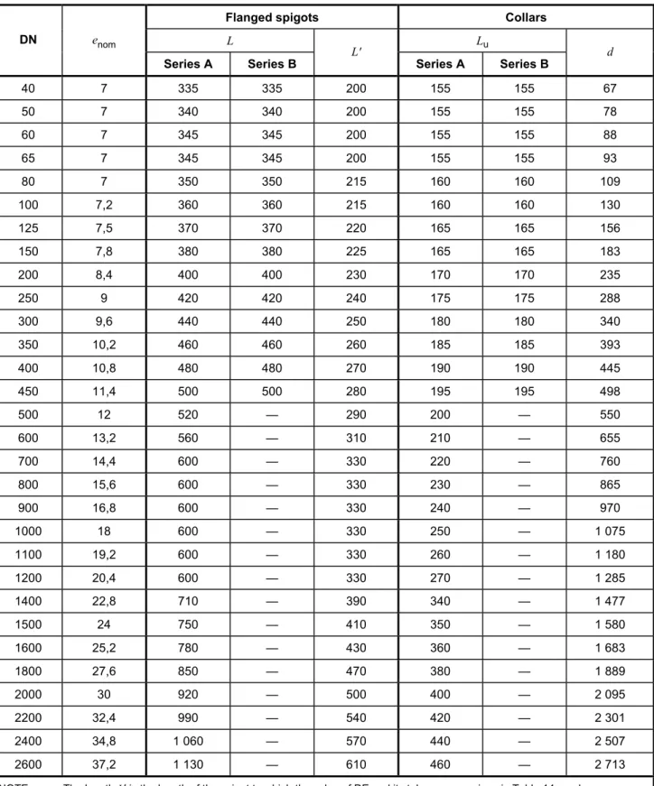
8.3.2 Flanged spigots See Figure 6 and Table 16.
Figure 6 — Flanged spigot
8.3.3 Collars
See Figure 7 and Table 16.
Table 16 — Dimensions of flanged spigots and collars
Flanged spigots Collars
L Lu
DN enom
Series A Series B L' Series A Series B d
40 7 335 335 200 155 155 67 50 7 340 340 200 155 155 78 60 7 345 345 200 155 155 88 65 7 345 345 200 155 155 93 80 7 350 350 215 160 160 109 100 7,2 360 360 215 160 160 130 125 7,5 370 370 220 165 165 156 150 7,8 380 380 225 165 165 183 200 8,4 400 400 230 170 170 235 250 9 420 420 240 175 175 288 300 9,6 440 440 250 180 180 340 350 10,2 460 460 260 185 185 393 400 10,8 480 480 270 190 190 445 450 11,4 500 500 280 195 195 498 500 12 520 — 290 200 — 550 600 13,2 560 — 310 210 — 655 700 14,4 600 — 330 220 — 760 800 15,6 600 — 330 230 — 865 900 16,8 600 — 330 240 — 970 1000 18 600 — 330 250 — 1 075 1100 19,2 600 — 330 260 — 1 180 1200 20,4 600 — 330 270 — 1 285 1400 22,8 710 — 390 340 — 1 477 1500 24 750 — 410 350 — 1 580 1600 25,2 780 — 430 360 — 1 683 1800 27,6 850 — 470 380 — 1 889 2000 30 920 — 500 400 — 2 095 2200 32,4 990 — 540 420 — 2 301 2400 34,8 1 060 — 570 440 — 2 507 2600 37,2 1 130 — 610 460 — 2 713
8.3.4 Double-socket 90° (1/4) bends See Figure 8 and Table 17.
Figure 8 — Double-socket 90° bend
8.3.5 Double-socket 45° (1/8) bends See Figure 9 and Table 17.
Table 17 — Dimensions of double-socket 90° and 45° bends
90° (1/4) bends 45° (1/8) bends
Lu Lu
DN enom
Series A Series B Series A Series B
40 7 60 85 40 85 50 7 70 85 40 85 60 7 80 90 45 90 65 7 85 90 50 90 80 7 100 85 55 50 100 7,2 120 100 65 60 125 7,5 145 115 75 65 150 7,8 170 130 85 70 200 8,4 220 160 110 80 250 9 270 240 130 135 300 9,6 320 280 150 155 350 10,2 — — 175 170 400 10,8 — — 195 185 450 11,4 — — 220 200 500 12 — — 240 — 600 13,2 — — 285 — 700 14,4 — — 330 — 800 15,6 — — 370 — 900 16,8 — — 415 — 1000 18 — — 460 — 1100 19,2 — — 505 — 1200 20,4 — — 550 — 1400 22,8 — — 515 — 1500 24 — — 540 — 1600 25,2 — — 565 — 1800 27,6 — — 610 — 2000 30 — — 660 — 2200 32,4 — — 710 — 2400 34,8 — — 755 — 2600 37,2 — — 805 —
8.3.6 Double-socket 22° 30' (1/16) bends See Figure 10 and Table 18.
Figure 10 — Double-socket 22° 30' bend
8.3.7 Double-socket 11° 15' (1/32) bends See Figure 11 and Table 18.
Table 18 — Dimensions of double-socket 22° 30' and 11° 15' bends
22° 30' (1/16) bends 11° 15' (1/32) bends
Lu Lu
DN enom
Series A Series B Series A Series B
40 7 30 30 25 25 50 7 30 30 25 25 60 7 35 35 25 25 65 7 35 35 25 25 80 7 40 40 30 30 100 7,2 40 50 30 30 125 7,5 50 55 35 35 150 7,8 55 60 35 40 200 8,4 65 70 40 45 250 9 75 80 50 55 300 9,6 85 90 55 55 350 10,2 95 100 60 60 400 10,8 110 110 65 65 450 11,4 120 120 70 70 500 12 130 — 75 — 600 13,2 150 — 85 — 700 14,4 175 — 95 — 800 15,6 195 — 110 — 900 16,8 220 — 120 — 1000 18 240 — 130 — 1100 19,2 260 — 140 — 1200 20,4 285 — 150 — 1400 22,8 260 — 130 — 1500 24 270 — 140 — 1600 25,2 280 — 140 — 1800 27,6 305 — 155 — 2000 30 330 — 165 — 2200 32,4 355 — 190 — 2400 34,8 380 — 205 — 2600 37,2 400 — 215 —
8.3.8 All socket tees See Figure 12 and Table 19.
Table 19 — Dimensions of all socket tees
Body Branch
Lu lu
DN× dn
enom, 1
Series A Series B enom, 2 Series A Series B
40 × 40 7 120 155 7 60 75 50 × 50 7 130 155 7 65 75 60 × 60 7 145 155 7 70 80 65 × 65 7 150 155 7 75 80 80 × 40 7 120 155 7 80 80 80 × 80 7 170 175 7 85 85 100 × 40 7,2 120 155 7 90 90 100 × 60 7,2 145 155 7 90 90 100 × 80 7,2 170 165 7 95 90 100 × 100 7,2 190 195 7,2 95 100 125 × 40 7,5 125 155 7 100 105 125 × 80 7,5 170 175 7 105 105 125 × 100 7,5 195 195 7,2 110 115 125 × 125 7,5 225 225 7,5 110 115 150 × 40 7,8 125 160 7 115 115 150 × 80 7,8 170 180 7 120 120 150 × 100 7,8 195 200 7,2 120 125 150 × 150 7,8 255 260 7,8 125 130 200 × 40 8,4 130 165 7 140 140 200 × 80 8,4 175 180 7 145 145 200 × 100 8,4 200 200 7,2 145 150 200 × 150 8,4 255 260 7,8 150 155 200 × 200 8,4 315 320 8,4 155 160 250 × 80 9 180 185 7 170 185 250 × 100 9 200 205 7,2 170 190 250 × 150 9 260 265 7,8 175 190 250 × 200 9 315 320 8,4 180 190 250 × 250 9 375 380 9 190 190 300 × 100 9,6 205 210 7,2 195 220 300 × 150 9,6 260 265 7,8 200 220 300 × 200 9,6 320 325 8,4 205 220 300 × 250 9,6 375 380 9 210 220 300 × 300 9,6 435 440 9,6 220 220
8.3.9 Double-socket tees with flanged branch, DN 40 to DN 250 See Figure 13 and Table 20.
Table 20 — Dimensions of double-socket tees with flanged branch, DN 40 to DN 250
Body Branch
Lu l
DN×dn
enom, 1
Series A Series B enom, 2 Series A Series B
40 ×40 7 120 155 7 130 130 50 ×50 7 130 155 7 140 140 60 × 40 7 — 155 7 — 130 60 ×60 7 145 155 7 150 150 65 × 40 7 — 155 7 — 130 65 ×65 7 150 155 7 150 155 80 × 40 7 — 155 7 — 135 80 × 60 7 — 155 7 — 155 80 ×80 7 170 175 7 165 165 100 × 40 7,2 — 155 7 — 145 100 × 60 7,2 — 155 7 — 165 100 ×80 7,2 170 165 7 175 170 100 × 100 7,2 190 195 7,2 180 180 125 × 40 7,5 — 155 7 — 160 125 × 60 7,5 — 155 7 — 180 125 ×80 7,5 170 175 7 190 185 125 × 100 7,5 195 195 7,2 195 195 125 × 125 7,5 225 225 7,5 200 200 150 × 40 7,8 — 160 7 — 170 150 × 60 7,8 — 160 7 — 190 150 ×80 7,8 170 180 7 205 200 150 × 100 7,8 195 200 7,2 210 205 150 × 125 7,8 — 230 7,5 — 215 150 × 150 7,8 255 260 7,8 220 220 200 × 40 8,4 — 165 7 — 195 200 × 60 8,4 — 165 7 — 215 200 ×80 8,4 175 180 7 235 225 200 × 100 8,4 200 200 7,2 240 230 200 × 125 8,4 — 235 7,5 — 240 200 × 150 8,4 255 260 7,8 250 245 200 × 200 8,4 315 320 8,4 260 260 250 × 60 9 — 165 7 — 260 250 ×80 9 180 185 7 265 265 250 × 100 9 200 205 7,2 270 270 250 × 150 9 260 265 7,8 280 280 250 × 200 9 315 320 8,4 290 290 250 ×250 9 375 380 9 300 300
8.3.10 Double-socket tees with flanged branch, DN 300 to DN 700 See Figure 13 and Table 21.
Table 21 — Dimensions of double-socket tees with flanged branch, DN 300 to DN 700
Body Branch
Lu l
DN×dn enom, 1
Series A Series B enom, 2 Series A Series B
300 × 60 9,6 — 165 7 — 290 300 ×80 9,6 180 185 7 295 295 300 × 100 9,6 205 210 7,2 300 300 300 × 150 9,6 260 265 7,8 310 310 300 × 200 9,6 320 325 8,4 320 320 300 × 250 9,6 — 380 9 — 330 300 × 300 9,6 435 440 9,6 340 340 350 × 60 10,2 — 170 7 — 320 350 × 80 10,2 — 185 7 — 325 350 × 100 10,2 205 210 7,2 330 330 350 × 150 10,2 — 270 7,8 — 340 350 × 200 10,2 325 325 8,4 350 350 350 × 250 10,2 — 385 9 — 360 350 × 350 10,2 495 500 10,2 380 380 400 ×80 10,8 185 190 7 355 355 400 × 100 10,8 210 210 7,2 360 360 400 × 150 10,8 270 270 7,8 370 370 400 × 200 10,8 325 330 8,4 380 380 400 × 250 10,8 — 385 9 — 390 400 × 300 10,8 440 445 9,6 400 400 400 × 400 10,8 560 560 10,8 420 420 450 × 100 11,4 215 215 7,2 390 390 450 × 150 11,4 270 270 7,8 400 400 450 × 200 11,4 330 330 8,4 410 410 450 ×250 11,4 390 390 9 420 420 450 × 300 11,4 445 445 9,6 430 430 450 × 400 11,4 560 560 10,8 450 450 450 × 450 11,4 620 620 11,4 460 460 500 × 100 12 215 — 7,2 420 — 500 × 200 12 330 — 8,4 440 — 500 × 400 12 565 — 10,8 480 — 500 × 500 12 680 — 12 500 — 600 × 200 13,2 340 — 8,4 500 — 600 × 400 13,2 570 — 10,8 540 — 600 × 600 13,2 800 — 13,2 580 — 700 × 200 14,4 345 — 8,4 525 — 700 × 400 14,4 575 — 10,8 555 — 700 × 700 14,4 925 — 14,4 600 —