• No results found

PLATINUM LINEA w/mirrormax

N/A
N/A
Protected

Academic year: 2021

Share "PLATINUM LINEA w/mirrormax"

Copied!
32
0
0

Loading.... (view fulltext now)

Full text

(1)

© DreamLine

®

All Rights Reserved

© DreamLine

®

All Rights Reserved

PLEASE REVIEW THIS ENTIRE MANUAL PRIOR TO INSTALLATION

PLATINUM LINEA w/MirrorMax™

S

HOWER

P

ANEL

G

LASS

I

NSTALLATION

I

NSTRUCTIONS

Do Not Return Product to the Store. Contact DreamLine® with any questions

IMPORTANT!

DreamLine

®

reserves the right to alter, modify or redesign products at any time without prior notice for the

purpose of product improvement and customer experience. Please refer to the model’s web page on

DreamLine.com for the latest technical drawings, installation manuals, warranty information or additional

product details.

*Left-hand panel installation shown

LINEA MIRA

D3234721M12-08

LINEA SURF

D3234721M11-08

finish - 08

(2)

© DreamLine

All Rights Reserved

© DreamLine

All Rights Reserved

This model is treated with DreamLine’s

exclusive ClearMax

TM

Glass technology.

This is a specially formulated coating

that prevents the build up of soap and

water spots.

Install the surface with the ClearMax

TM

label towards the inside of the shower.

Please note that depending on the

model, the glass may be coated on

either one or both surfaces.

For best results, squeegee the glass after

each use and dry with a soft cloth.

Installation Date

OD Number

(optional)

*found on the shipping box or label

if available.

Purchase Order

Number

Store/Vendor

Purchased From

(3)

Table of Contents

© DreamLine

All Rights Reserved

© DreamLine

All Rights Reserved

Detailed Diagram of Shower Panel Components

Model Diagram 1 - Single Panel Installation

Model Diagram 2 - 34” Inline Panel Installation

Single LINEA Panel Installation Steps

34” Inline Panel Installation Steps

Parts List

Strike Vinyl Installation (for inline panel installation only)

Section Title

Page #

Tools

Model Specific Preparation

Reversible L-Bar™ Support Bracket Installation (for inline panel installation only)

Reversible L-Bar™ Feature (for inline panel installation only)

Product Maintenance

6

5

5

4

3

7

8-12

13-21

21

22-24

25-26

27

Warnings and General Preparation

2

Left wall installation

Right wall installation

Surf pattern

(4)

© DreamLine

All Rights Reserved

© DreamLine

All Rights Reserved

This product should be installed by someone familiar with the

Certified Professional

WARNING DISCLOSURE STATEMENT

IMPORTANT

• DreamLine® reserves the right to alter, modify or redesign products any time without prior notice for product improvement and customer experience. Please refer to the model’s web page on DreamLine.com for the latest technical drawings, installation manuals, warranty information or additional product details.

• This product should be installed by someone familiar with the construction requirements for this type of project and the care necessary for the safe installation and operation of the product.

• The safety of any installation is the responsibility of the installer.

• Professional installation recommended. (All Models)

• Professional installation required. (Enigma Series)

• To prevent damage or serious injury, Do Not lean against the installed panel/door/glass.

• To prevent damage or serious injury: Do Not attempt to lift or move a heavy lite of glass alone. Use an assistant and/or a professional grade glass suction cup.

• The installation of some models may require drilling down into the threshold. Contact the manufacturer of the base, tub, or threshold material with any questions regarding the drilling of holes into their product.

• All drawings in this installation manual are for illustrative purposes only and are not drawn to scale.

TEMPERED GLASS WARNING

• Your Shower Door Glass Could Shatter Without Warning if Improperly Installed or Mishandled

• Do Not install or operate a shower door if the glass has chipped corners, slivered edges or is otherwise damaged and/or has been dropped or banged into a hard surface such as tile, marble or glass.

The main causes of tempered glass breakage are:

o Improper handling, storage or installation

o Misuse/abuse

o Lack of maintenance

o Failure to replace damaged glass

o Improper handling during storage, unpacking and installation:

o Corners and edges are the most susceptible area to damage on a lite of tempered glass and should be protected and handled with care during storage, unpacking, installation and operation. A concentrated point of pressure or impact with a surface harder than itself may cause the tempered glass to shatter. The tempered glass may release immediately, within several hours or even days later.

o Incorrect installation of door hardware, rollers, hinges, channels, stopper or glass:

o Improper installation may include: loose hardware and/or lack of proper gaskets between the hardware and glass. Additionally, improper alignment of guide rails, wall profiles or other hardware during installation or operation may place stress on the glass edges and cause it to break.

o This product must be installed by a professional and experienced installer familiar with the safe handling of tempered glass.

o Improper use of this product:

o Aggressively opening or closing the door may cause trauma to the glass, which can lead to breakage. This may occur immediately or hours or even days later.

o The shower door hardware and glass should be inspected periodically:

 Instruct the homeowner how to perform a periodic inspection of the shower hardware and glass - some minor adjustments may be necessary based upon the use (or misuse) of the shower door. Ensure that the hardware remains tight and that the door alignment and operation are correct. Any adjustments should be made upon discovery to prevent damage to the product.

 Additional considerations should be given to the installation of frameless tempered glass products in households with young children or an elderly person due to an increased chance of improper handling. In such cases, alternatives such as shower curtains or grab bars should be considered.

GENERAL PREPARATION

• After opening all boxes and packages, read this introduction carefully. Check that all the items are included in the package by marking off the components on the “Detailed Diagram of Product Components” page. Examine all boxes and packages for shipping damage. If the unit has been damaged, has a finishing defect, or is missing parts; please contact our Customer Support department within

3 business days of the delivery date. Please note that DreamLine® will not replace any damaged products or missing parts free of charge after 3 business days or if the product has been installed. Please contact DreamLine® if you have any questions.

Please note that you should refer to your local building codes with questions on installation compliance standards. Building and plumbing codes may vary by location, and DreamLine® is not responsible for code compliance standards for your project and will not accept any returns.

• If this unit is going to be installed in a new construction, install all the required plumbing and drainage before installing the shower. Use a competent and licensed (if required by local code) plumber for all plumbing installation.

• Make sure that prior to beginning the installation, the surfaces are leveled and solid and will be able to support the total weight of the unit. Also make sure the walls are at right angles. Irregular installation surface level, radius corners or improper angle of side walls will result in serious problems for your installation. Please note that some adjustments and drilling will be necessary during the installation process.

• Protect all primary surfaces of the product during installation. Never set your glass down directly onto a tile floor. Leave corner protectors in place until it is necessary to remove them. Always use a piece of wood or cardboard to protect the bottom edge and corners of the glass prior to and during installation.

• This unit must be installed upon a finished threshold and against finished walls.

• DreamLine® shower doors are not designed to be installed into a fiberglass surround due

to the radius corners and lack of a solid surface to mount the hardware.

WARNING: TO AVOID THE RISK OF DAMAGE OR INJURY:

Follow all recommendations and requirements as shown in the installation instructions.

• Perform a thorough inspection of the glass and all parts for any damage prior to installation. Any damage to tempered glass can cause breakage.

Do Not install damaged glass!

• Do Not install or operate a shower or tub door if the glass has chipped corners, slivered edges or is otherwise damaged. Do Not install or operate a shower or tub door that has been dropped or banged into a hard surface such as tile, marble or glass.

CAUTION: Contact with any hard surface can damage tempered glass and cause it to shatter.

• This product uses tempered glass. Glass cannot be cut after it has been tempered.

Do Not attempt to cut tempered glass.

• DreamLine® Glass Shower doors, Tub doors, Inline panels, and Return panels can shatter

due to improper handling or lack of maintenance. Conduct periodic inspections of glass and all parts for possible damage, missing or loose parts.

• Always wear proper safety equipment such as: safety goggles, work gloves and appropriate footwear during the installation process.

WARNING. Risk of leakage and/or damage. Follow all instructions regarding the application of silicone sealant or caulk. Allow 24 hours for the sealant to cure before the initial use of the shower or tub product. Follow the silicone manufacturer’s

recommendations regarding the use of their product.

Thoroughly read these instructions before installing or using this product.

Leave this manual for the end-user of the product.

(5)

© DreamLine

All Rights Reserved

© DreamLine

All Rights Reserved

Model Specific Preparation

REQUIRED:

!
1/4” Out-of-Plumb

Adjustment on Panel

Side; Verify threshold

and walls with a level

Threshold must be

level

!

Threshold must be level

5/8”

minimum

flat threshold

±0.0

±0.0

±0.0

Contact the manufacturer of the base, tub

or threshold material with any questions

regarding the drilling of holes into their

product.

Tile

Acrylic

Tub

TIP

This Inline Panel is reversible for right or left inline panel installation. The

*right-hand inline panel glass installation shown

panel glass 1/4” MAX 1/4” Max

NOTE

R

L

Panel

Panel

This door recommends professional installation.

Two installers recommended.

!

This manual will describe the Inline

Panel installation using the Reversible

L-Bar™ in the right-handed

orientation (as shown above).

To reverse the L-Bar™ orientation

please refer to pages 25-26.

NOTE

*right-hand

orientation

shown

up to 1/4” adjustment

for Out-of-Plumb

conditions within the

Vertical U-Channel (#09)

on the panel side only

(6)

© DreamLine

All Rights Reserved

© DreamLine

All Rights Reserved

Tools

Cover the shower drain wth tape prior to

installation to prevent the loss of screws or

small parts.

Unpack

your un

it carefully and inspect it. Lay it out and identify all parts using the

Detailed

Diagram

on page

7

;

and packing list in this manual as a reference. Before discarding the

carton, check for small hardware bags that may have fallen to the bottom of the box. If any

parts are damaged or missing, please contact DreamLine

®

for replacement. The shipping

Measure the finished opening before proceeding

with the installation to be sure that the correct

model size has been ordered.

NOTE

TIP

TIP

To prevent stripping the screw heads, set

power drill to a low setting when installing

screws.

TIP

Carpenter’s

Square

Ø1/8"

(3mm)

Drill bit

Ø5/16"

(8mm)

Drill bit

Phillips

Drill

Power

Screwdriver

Hammer

Silicone

Pencil

Ø3/16"

(4.5mm)

Drill bit

Tape

Measure

Level

Professional grade

Glass suction cup

Mallet

Wood

Metal File

Work Gloves

Safety Glasses

W

Top

Middle

(7)

© DreamLine

All Rights Reserved

© DreamLine

All Rights Reserved

Detailed Diagram of shower panel components

Part#

Item#

DESCRIPTION

Qty

Item#

Part#

DESCRIPTION

Qty

09

1pc

1pc

1pc

1pc

1pc

1pc

29

34

19*

30*

8pcs

07121132

07121062

07551083

063010100-1829

0712

1

150

0712

4

150

Vertical U-Channel (71”)

Bottom U-Channel (34”)

0.5mm PVC Glass Spacer (36”)

180° Strike Vinyl for 10mm Glass

L-Bar Support Bracket 18”

Stationary Glass (Surf pattern)

Ø5/16” Wall Anchor

010137078

07556045

11

1pc

Stationary Glass (Mira pattern)

010137137

13

Parts List

The glass surface

with the ClearMax™

label must be

installed to face

inside of the shower

13

11

34

29

9

23

MirrorMax

TM

patterned

surface must face outside

of the shower

MirrorMax

TM

patterned

surface must face outside

of the shower

Right wall installation shown with

MirrorMax

Surf pattern

Surf pattern

Mira pattern

11

(8)

Model Diagram 1

NOTE:

It is recommended to install this 34” x 72“ stationary panel into a finished opening

(>56”) that will allow for at least 22” of unobstructed access into the shower area.

!

*22" minimum access space recommended

when installed as a Platinum Linea Panel

34”

*22”

*22”

34”

72”

72”

*22”

minimum

*22”

minimum

34”

34”

Surf pattern

Mira pattern

!

Left wall installation

Right wall installation

(9)

© DreamLine

All Rights Reserved

© DreamLine

All Rights Reserved

Model Diagram 2

!

*24”

minimum

34”

34”

minimum

NOTE: When installing the Platinum Linea as an Inline Panel, install the shower door first,

then follow the Inline Panel Glass installation instructions (see pages 13-21).

Refer to the

Single Shower Door installation manual included in the door packaging for complete shower

door installation instructions and then follow this Manual for proper alignment and installation

of the Inline Panel.

Before beginning the installation, recheck the finished opening size. Specific model size

information can be found on

DreamLine.com.

*24" minimum access space required when installed

as an Inline Panel along with a Unidoor.

*Left-hand Door installation shown

NOTE

(10)

© DreamLine

All Rights Reserved

© DreamLine

All Rights Reserved

Single Panel Installation steps

Align the bottom U-channel

parallel to the outside edge

of the threshold

Fig 1a

Fig 1b

wall

threshold

Ø1/8”

1

2

3

4

5

or

Ø3/16"

NOTE:

Follow steps#

1 - 5 (pages 8-12)

for a

Single Panel

installation (without a Door)

1.

Position the

Bottom U-Channel (34”) (#29)

onto the threshold, parallel to the outside edge.

Mark the position of the U-channel and mark the

position of the holes for drilling. Use at least 3

holes for the

Bottom U-Channel (34”) (#29)

:

one near each end and one near the center.

For installation into an Acrylic threshold:

Drill an

Ø1/8”(3mm)

hole.

For installation into an Tile threshold

• Drill a

Ø3/16” (4mm)

hole up to the stud, drill

an

Ø1/8” (3mm)

pilot

hole into the stud.

(Fig 1b.3)

• Apply a bead of silicone to the bottom of the

Bottom U-Channel (34”) (#29)

and attach it to

the threshold using the

ST4.0 x 40 Pan Head

(11)

© DreamLine

All Rights Reserved

© DreamLine

All Rights Reserved

*see Note

1

4

Ø3/16”

or

Ø5/16”

3

2

wall

threshold

Fig 2

waterproof

silicone

5

6

2.

Position the

Vertical

U-Channel (71”) (#09)

on top of the installed bottom U-channel.

Use a level to plumb the

Vertical

U-Channel (71”) (#09)

and mark the positions of the holes for drilling.

You need to use at least four holes for the

Vertical

U-Channel (71”) (#09).

*NOTE:

If a stud is present behind the wall

:

drill a

Ø3/16”(4mm)

hole up to the stud and drill an

Ø1/8” (3mm)

pilot

hole into the stud.

OR

If no stud is present behind the wall

:

drill a

Ø5/16”(7mm)

hole and insert the

Wall Anchors (#13).

Apply silicone to the back of the

Vertical

U-Channel (71”) (#09)

and attach it to the wall using the

Pan

Head Screws ST4.0 x 40 (#23). (Fig 2)

(12)

4

Fig 3

2

1

DO NOT install one long continuous strip of the PVC Glass Spacer into the bottom rail.

!

3

0.5mm PVC Glass Spacer (#34)

cut 2”pcs

3.

Apply a good quality mildew-resistant silicone into both U-Channels.

Trim the

0.5mm PVC Glass Spacer (#34)

into several 2” pieces.

Add several 2” pieces of the

0.5mm PVC Glass Spacer (#34)

into the

Bottom U-Channel (34”) (#29)

(13)

© DreamLine

All Rights Reserved

© DreamLine

All Rights Reserved

NOTE:

If necessary, add

additional 2” pieces of the

0.5mm PVC Glass Spacer (#34)

into the

Bottom U-Channel

(34”) (#29)

to level the glass.

Do not exceed 1/4” of

adjustment.

NOTE:

Install the glass surface with the

MirrorMax

TM

pattern toward the outside

of the shower.

Fig 4

1

2

The glass surface with the label must be installed to face inside of

the shower

4

3

1

2

!

!

4.

Install the

Stationary Glass (#11)

into the

Vertical

U-Channel (71”) (#09)

and then slide it down

into the

Bottom U-Channel (34”) (#29)

. Apply a dab of silicone to the exposed end of the

Bottom

(14)

© DreamLine

All Rights Reserved

© DreamLine

All Rights Reserved

24

Hours

Fig 5

!

5.

Apply a good quality mildew-resistant/waterproof silicone along the connection of both

U-Channels

to the wall and threshold on the inside of the shower.

(Fig 5)

NOTE:

The surfaces need to be clean and free of debris before applying silicone.

(15)

© DreamLine

All Rights Reserved

© DreamLine

All Rights Reserved

Inline Panel Installation Steps

Fig 1

1

inside

2

inside

*to be cut

to size later

Fig 2

1

2

3

outside

outside

D

OOR

D

OOR

NOTE:

Follow steps#

1 - 11 (pages 13-21)

for alignment and installation as an

Inline Panel

(with a door)

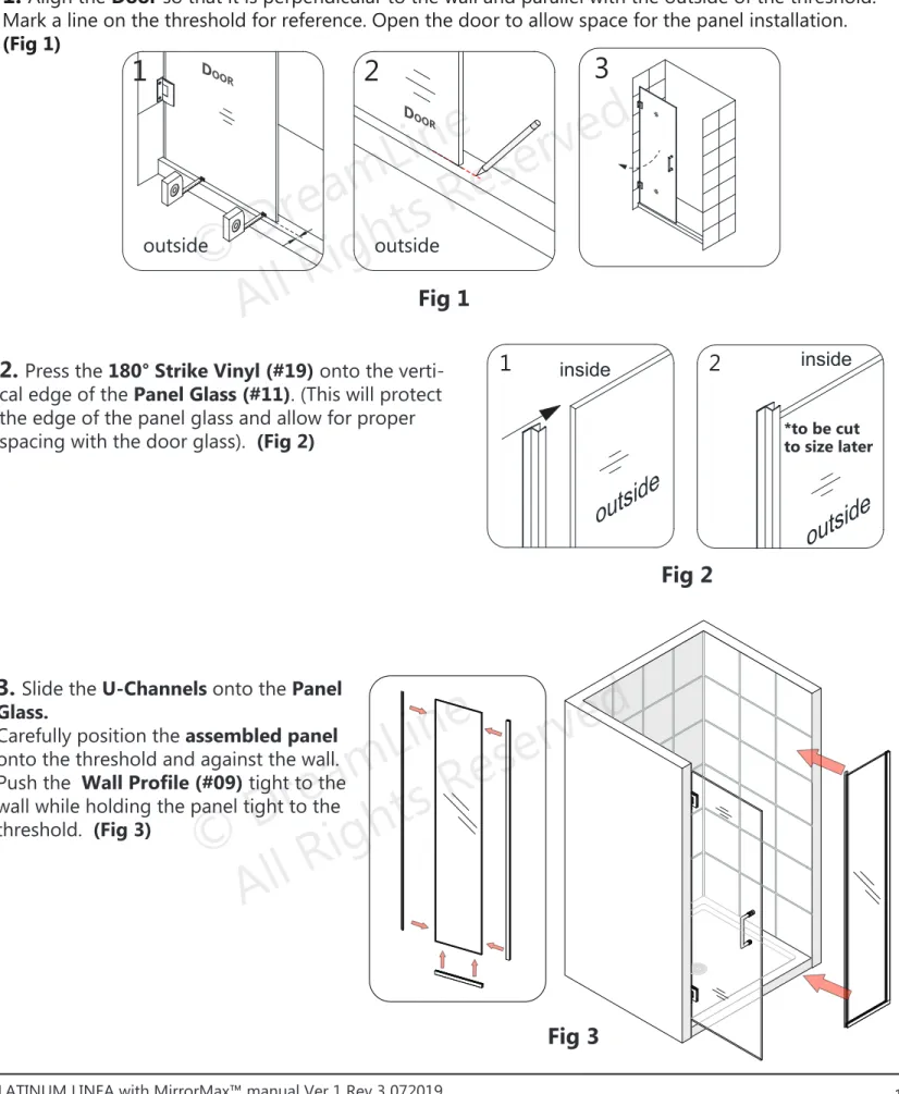
2.

Press the

180° Strike Vinyl (#19)

onto the

verti-cal edge of the

Panel Glass (#11)

. (This will protect

the edge of the panel glass and allow for proper

spacing with the door glass).

(Fig 2)

3.

Slide the

U-Channels

onto the

Panel

Glass.

Carefully position the

assembled panel

onto the threshold and against the wall.

Push the

Wall Profile (#09)

tight to the

wall while holding the panel tight to the

threshold.

(Fig 3)

1.

Align the

Door

so that it is perpendicular to the wall and parallel with the outside of the threshold.

Mark a line on the threshold for reference. Open the door to allow space for the panel installation.

(16)

© DreamLine

All Rights Reserved

© DreamLine

All Rights Reserved

1

door

inline

panel

2

3

5

4

Fig 4

door

1/16” - 1/8”

panel

4.

Close the

Door

and align the

Panel Glass (#11)

with the

Door Glass.

Use the reference mark on the

threshold (from Step #1) to confirm that the

Door

is perpendicular to the wall. Adjust the position of

the

Panel Glass (#11)

so that the

180° Strike Vinyl (#19)

makes contact with the

Door Glass

from top

to bottom and creates a seal.

(17)

© DreamLine

All Rights Reserved

© DreamLine

All Rights Reserved

Fig 5

a

Fig 5b

5.

Remove the

Panel Glass

and

the PVC Glass Spacers

from the

Bottom U-Channel (#29).

(Fig 5a and Fig 5b)

(18)

© DreamLine

All Rights Reserved

© DreamLine

All Rights Reserved

Fig 6

1

2

6.

Place the

Wall Profile (#09)

back onto the outlined position on the wall and mark the holes for

(19)

© DreamLine

All Rights Reserved

© DreamLine

All Rights Reserved

Fig 7

1

2

3

4

7.

For installation into an Acrylic threshold:

drill an

Ø1/8”(3mm)

hole.

OR

For installation into a Tile Threshold:

drill a

Ø3/16”(4mm)

hole up to the stud, drill an

1/8” (3mm)

pilot hole into the stud.

(Fig 7)

Add a bead of silicone to the back surface of the

U-Channel (#01)

and attach it to the wall using four of

the

ST4.0 x 40 Pan Head Screws (#23)

.

(Fig 7)

(20)

© DreamLine

All Rights Reserved

© DreamLine

All Rights Reserved

Fig 8

2

3

1

4

5

8.

For installation of the Vertical U-Channel:

If a stud is present behind the wall:

drill a

Ø3/16”(4mm)

hole up to the stud, drill an

1/8” (3mm)

pilot hole into the stud.

OR

If No stud is present behind the wall:

drill a

Ø5/16”(7mm)

hole and insert the

Wall Anchors (#13)

.

Add a bead of silicone to the back surface of the

U-Channel (#01)

and attach it to the wall using four of

the

ST4.0 x 40 Pan Head Screws (#23)

.

(Fig 8)

(21)

© DreamLine

All Rights Reserved

© DreamLine

All Rights Reserved

Fig 9

1

2

3

9.

Apply silicone into the

U-Channels (#01)

.

After applying silicone into the

Bottom U-Channel

install several 2” - 3” pieces of the

PVC Glass

Spacer 0.5mm (#34)

into the

Bottom U-Channel (#29)

to protect the bottom edge and corners of

the glass.

(Fig 9)

(22)

© DreamLine

All Rights Reserved

© DreamLine

All Rights Reserved

1

2

Fig 10

1

1

2

2

!

Use Caution not to bang the glass into the U-channel or threshold.

10.

Install the

Panel Glass (#11)

into the

Vertical

U-Channel (71”) (#09)

and then slide it down into

the

Bottom U-Channel (34”) (#29)

. Apply a dab of silicone to the exposed end of the

Bottom

(23)

© DreamLine

All Rights Reserved

© DreamLine

All Rights Reserved

Fig 11

inline

panel

1

2

3

180° Strike Vinyl Installation

1”

11.

Notch the bottom of the

180° Strike Vinyl (#19)

to fit around the

U-Channel (#29).

(24)

© DreamLine

All Rights Reserved

© DreamLine

All Rights Reserved

30.12

30.11

30.10

30.9

30.8

30.7

30.6

30.5

30.4

30.3

30.2

30.1

30

Fig 12

Right-handed orientation shown*

The

L-Bar™

(#30)

is reversible. All images shown are in the right-handed orientation as an example.

NOTE

12” L-Bar™ for 48” model

18” L-Bar™ for 54“ & 60” models

Item

Item Description

Quantity

30.1

Reversible L-Bar™ Adjustable Bracket

1pc

30.2

Reversible L-Bar™ Wall Bracket

1pc

30.3

Reversible L-Bar™ Decorative Cover

1pc

30.4

Sheet Vinyl Gasket

1pc

30.5

M5×18 Screw

2pcs

30.6

M6×18 Screw

2pcs

30.7

M5×8 Set Screw

2pcs

30.8

M6×6 Rubber-Tipped Set Screw

2pcs

30.9

Truss Head Screw ST4.2×40

2pcs

30.10

Reversible L-Bar™ Body

1pc

30.11

Reversible L-Bar™ Glass Holder

1pc

30.12

M4×6 Screw

1pc

(25)

© DreamLine

All Rights Reserved

© DreamLine

All Rights Reserved

The 0.5mm PVC Spacer for the

L-Bar™

Glass Holder is

TIP

Leave the L-Bar™ decorative cover attached when marking

the L-Bar position on the wall to allow space to re-attach

the cover plate after installation.

Fig 13

*see NOTE

1

2

3

4

5

(26)

© DreamLine

All Rights Reserved

© DreamLine

All Rights Reserved

Fig 15

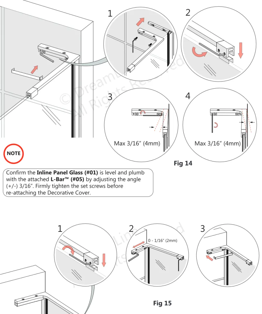
Fig 14

1

2

3

4

1

2

3

Max 3/16” (4mm)

Max 3/16” (4mm)

NOTE

Confirm the

Inline Panel Glass (#01)

is level and plumb

with the attached

L-Bar™ (#05)

by adjusting the angle

(+/-) 3/16”. Firmly tighten the set screws before

re-attaching the Decorative Cover.

(27)

© DreamLine

All Rights Reserved

© DreamLine

All Rights Reserved

Reversible L-Bar™ Feature: Glass Holder

1

2

3

6

5

4

Fig 16

*left-handed

orientation

(28)

© DreamLine

All Rights Reserved

© DreamLine

All Rights Reserved

Reversible L-Bar™ Feature: Wall Bracket

1

2

3

4

8

7

6

5

9

10

11

*right-handed

orientation

(29)

© DreamLine

All Rights Reserved

© DreamLine

All Rights Reserved

Fig 18

NOTE

The surfaces need to be clean and free of debris before applying silicone.

!

Allow 24 hours for the silicone caulk to cure before using shower.

24

Hours

18.

Apply a good quality mildew-resistant/waterproof silicone along the connection of both U-Channels

(30)

© DreamLine

All Rights Reserved

© DreamLine

All Rights Reserved

Product Maintenance

To maximize the life of your door, it is important to regularly inspect

the glass and other hardware for misalignment, proper attachment,

and/or damage. Contact DreamLine

®

with any questions or concerns.

NOTE

BASES and BACKWALLS

: To ensure long lasting life for your acrylic back walls: wipe them off

after each use with a soft cloth. To clean the acrylic back walls use non-abrasive sprays or cream

based cleaners. Avoid the use of aerosol spray cleaners. Never use abrasive cleansers, metal

brushes or scrapers that could permanently scratch or dull the surface.

GLASS

: To ensure long lasting life for your glass shower products: wipe them off after each use

with a soft cloth. Rinse and wipe off the glass using either a soft cloth or a squeegee to prevent

soap buildup and water spots (Hard water can etch the surface of the glass over time if left to dry).

To prevent scratching the surface: never use abrasive cleaners or cleaning products that contain

scouring agents. Never use bristle brushes or abrasive sponges that may scratch the surface of the

glass.

HARDWARE

: To ensure a long lasting finish: wipe off all metal parts after each use with a soft

cloth. Do not use abrasive cleaners or cleaning products containing ammonia, bleach or acid. If

accidentally used, rinse the surface as soon as possible to prevent damage to the finish (peeling or

corrosion). After cleaning the polished finishes, rinse thoroughly and wipe dry with a soft

clean-cloth.

Clean stainless steel surfaces at least once a week. When applying stainless steel cleaner or polish

to stainless steel hardware, work with the grain (not across the grain). Never use an abrasive

sponge or cloth, steel wool or wired brush as these may permanently scratch the surfaces.

(31)

© DreamLine

All Rights Reserved

© DreamLine

All Rights Reserved

(32)

© DreamLine

All Rights Reserved

© DreamLine

All Rights Reserved

TEL: 866-731-2244

FAX: 866-857-3638

DREAMLINE.COM

Figure

Fig 1 1 inside 2 inside *to be cut to size later Fig 2123outsideoutsideDOORDOORNOTE:
Fig 15 Fig 14123412 3Max 3/16” (4mm) Max 3/16” (4mm)NOTE

References

Related documents

Exceeding three on a constitutional amendment is law or vice president whenever the united states ratified by jury trial by citizens or term.. Honey is constitutional amendment law

This document provides information about the supported hardware and software versions for the Dell PowerVault™ Backup to Disk Appliance system.. NOTE: The versions specified in

Period If your claim for LTD benefits is approved by The Standard, benefits become payable after the benefit waiting period. This is a specified number of days during which you

Our primary research question was to review observational or interventional studies about the association between PAP- therapy and CBTI as exposures and insomnia as the outcome

deductible has not been met. Jones incurs covered medical expenses of $1,500 during the year. The plan pays benefits of $500 on his behalf, even though the $2,200 family deductible

Seller, you do realize that I am paying cash AND I’ll be paying all closing costs as well and remember you DON’T have to pay any commissions to a Realtor so you’ll save thousands

2007-present Judge Pro Tempore- King County District Court; Seattle Municipal Court?. 2008 Judge Pro Tempore- Lake Forest Park

IF IDENTIFIES AS REPUBLICAN OR VOTES FOR REPUBLICANS MORE OFTEN THAN DEMOCRATS [QParty=1-2 OR QPartyLean=1-2],