EPON User Manual
(
Switch Part
)
Document Version: V2.1
Release Date: 2016-1-10
GCOM Technology Co., Ltd.
Statements
:
All rights reserved by GCOM.
No part of this manual may be translated, extracted, duplicated by
any forms or any means without prior written permission from
G-COM.
Attention:
This manual will be updated periodically with the upgraded of the
product. Unless otherwise specified in the agreement, this manual is
presented as operation guide without warranty of any kind express or
implied.
Address: B-Building, FUTONG Optical Park, #2 Songpingshan Rd, North Hi-Tech Industry Park, Nanshan, Shenzhen
Website: http://www.szgcom.com Email: [email protected] Tel:
CONTENT
1. Login OLT... 1
1.1 Overview for Login OLT...1
1.2 Login OLT... 1
1.2.1 Login OLT via Serial Port...1
1.2.2 Login OLT via Telnet...2
1.2.3 Login OLT via SSH...3
1.2.4 Login OLT via Web... 4
1.2.5 Manage OLT via Netmanager Software...4
1.3 Command Line Interface...5
1.3.1 Overview for Command Line Interface...5
1.3.2 Command Line Mode...5
1.3.3 Comprehension of Command Syntax...7
1.3.4 Syntax Help... 8
1.3.5 History Command...9
1.3.6 Types of Command Parameters...9
1.3.7 Error Message... 9
2. Equipment Management...11
2.1 Overview for User Management Functions...11
2.1.1 User Management Configuration...11
2.1.2 Silence Mechanism...12
2.2 Second-tier Password Authentication...13
2.2.1 Overview for Second-tier Password Authentication...13
2.2.2 Configure the Second-tier Password Authentication...13
2.2.3 Configuration Example for Second-tier Password Authentication...14
2.3 Remote Authentication...15
2.3.1 Overview for Remote Authentication...15
2.3.2 Configure the Authentication Mode...15
2.3.3 Configure Radius Remote Authentication...15
2.3.4 Configure Tacacs+ Remote Authentication...16
2.3.5 Configuration Example for Remote Authentication...17
2.4 IPLimit... 18
2.4.1 Overview for IP Limit...18
2.4.2 Configure IP Limit...18 2.4.3 Configuration Example...18 2.5 Timeout Configuration...19 2.5.1 Timeout overview...19 2.5.2 Timeout Configuration...19 3. Port Configuration... 20
3.1 Port Basic Configuration...20
3.1.1 Enter Port Configuration Mode...20
3.1.2 Enable the Port... 20
3.1.3 Interface Description...20
3.1.4 Duplex Mode... 21
3.1.5 Interface Rate...21
3.1.6 Switch between Optical Port and Copper Port of Combo-Port...21
3.1.7 Rate Control Mode...22
3.1.8 Configuration Example...22
3.2 Port Aggregation Configuration...23
3.2.1 Overview for Port Aggregation...23
3.2.2 Configure the Aggregation Group ID...24
3.2.4 Configure the Load Balancing Policy...24
3.2.5 Configure the System Priority...25
3.2.6 Configure the Port Priority...25
3.2.7 LACP Configuration Example...25
3.3 Port Isolation Configuration...26
3.3.1 Port Isolation...26
3.3.2 Configuration Example for Port Isolation...27
3.4 Loopback... 28
3.4.1 Loopback Overview...28
3.4.2 Configure Loopback...28
3.4.3 Loopback Configuration Example...28
3.5 VCT - Virtual Cable Test...28
3.5.1 VCT Overview... 28
3.5.2 Configure VCT...29
3.5.3 VCT Configuration Example...29
3.6 DDM- Digital Diagnostic Monitor...30
3.6.1 DDM Overview...30
3.6.2 Show DDM Test Information...30
3.6.3 DDM Configuration Example...30
3.7 Port-Statistic... 31
3.7.1 Ordinary Port Packet- statistic...31
3.7.2 CPU Port- statistic...31
3.7.3 5-minutes Port Rate Statistic...32
3.7.4 Port Statistic of Aggregation Group...32
3.7.5 Higig Interface Statistic...32
3.7.6 Configuration Example of Interface Statistic...33
3.8 Flow Control... 34
3.8.1 Overview for Flow Control...34
3.8.2 Configure Flow Control...34
3.8.3 Configuration Example for Flow Control...34
4. VLAN Configuration... 36
4.1 VLAN Overview... 36
4.1.1 Vlan Configuration...36
4.1.2 Interface Default vlan ID...36
4.1.3 Interface Type...37
4.1.4 VLAN Attributes Based on Hybrid Interface...37
4.1.5 VLAN Attributes Based on Trunk Interface...38
4.1.6 Configure port priority...38
4.1.7 Ingress Filtering...38
4.1.8 Configure Types of Interface acceptable-frame...38
4.1.9 Configuration Example...39
4.2 QinQ Configuration...42
4.2.1 QINQ Overview...42
4.2.2 Static QINQ Overview...44
4.2.3 Configuration Example for Static QinQ...45
4.2.4 Dynamic QINQ Overview...45
4.2.5 Dynamic QINQ Configuration Example...46
4.3 Adjustable Function of VLAN Tag TPID Value...48
4.3.1 Configure TPID Value of VLAN Tag to be Adjustable...48
4.3.2 Configuration Example for TPID Value Adjustable...48
4.4 GVRP Configuration...48
4.4.1 GVRP Overview...48
4.4.2 Enable GVRP...49
4.4.4 Configure the VLAN which Forbids the Port to Forward...49
4.4.5 GVRP Display and Debugging...49
4.4.6 GVRP Configuration Example...50
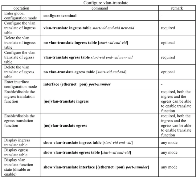
4.5 N:1 VLAN Translation...53
4.5.1 N:1 VLAN Translate Overview...53
4.5.2 Configure vlan-translate...53
4.5.3 Configure vlan-swap...54
4.5.4 Configuration Example for N:1 vlan-swap...54
4.6 MAC-Based VLAN Configuration...56
4.6.1 Overview for MAC-Based VLAN...56
4.6.2 Configure MAC-Based VLAN...56
4.6.3 Configuration Example for MAC-Based VLAN...56
4.7 Protocol-Based VLAN...58
4.7.1 Protocol-Based VLAN Configuration...58
4.7.2 Configure Protocol-Based VLAN (Method One)...58
4.7.1 Configure Protocol-Based VLAN (Method Two)...59
4.7.2 Example for Protocol-Based VLAN (Method One)...59
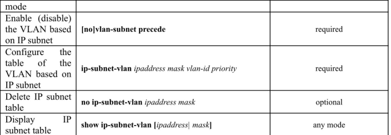
4.8 IP-subnet VLAN... 60
4.8.1 Overview for IP Subnet-Based VLAN...60
4.8.2 Configure IP Subnet-Based VLAN...60
4.8.3 Configuration Example...60
4.9 VLAN-trunking Configuration...61
4.9.1 VLAN-trunking Overview...61
4.9.2 Configure Vlan-trunking...62
4.9.3 Configuration Example for Vlan-trunking...62
5. MAC Address Table Configuration...63
5.1 Configure MAC Address Table...63
5.1.1 Configure MAC Address Table Aging Time...63
5.1.2 Add MAC Address Table by Manual...63
5.1.3 Add Blackhole MAC Address...64
5.1.4 Modify the Type MAC Table...64
5.1.5 Enable/disable MAC Address Learning...64
5.1.6 Quantity Limitation on MAC Address Learning Table...64
5.2 Local-switch Function...65
5.2.1 Configure Local-switch...65
5.2.2 Configuration Example for Local-switch...65
5.3 Slf-control Function...66
5.3.1 Configure Slf-control...66
5.3.2 Configuration Example for Slf-control...67
5.4 DLF-control Overview...67
5.4.1 Configure DLF-control...67
5.4.2 Configuration Example for DLF-control...68
6. Multicast Configuration...69
6.1 IGMP-Snooping Configuration...69
6.1.1 Overview for IGMP-Snooping...69
6.1.2 Enable IGMP-Snooping...69
6.1.3 Configure igmp-snooping Timer...69
6.1.4 Configure fast-leave...70
6.1.5 Configure the Maximum Learning Number of Multicast Groups...70
6.1.6 Configure igmp-snooping Multicast Learning Strategy...71
6.1.7 Configure igmp-snooping Querier...71
6.1.8 Configure the Routing Port...72
6.1.9 Configure Multicast VLAN...72
6.1.11 Configure the Suppression Multicast Report...73
6.1.12 Configure Whether to Drop Query / Report Packets...73
6.1.13 Configure the Multicast Preview Function...73
6.1.14 Configure the Profile Black and White List...74
6.1.15 Igmp-snooping Display and Maintenance...75
6.1.16 Configuration Example...75
6.2 MLD Snooping Configuration...77
6.2.1 MLD Snooping Overview...77
6.2.2 Enable MLD Snooping...78
6.2.3 Configure MLD Snooping Timer...78
6.2.4 fast-leave Configuration...78
6.2.5 Configure the Maximum Number of Multicast Groups...78
6.2.6 Configure the Multicast Learning Strategy of MLD Snooping...79
6.2.7 Configure the MLD-Snooping Querier...79
6.2.8 Configuring the Routing Port...80
6.2.9 Configure a Multicast VLAN...80
6.2.10 MLD Snooping Display and Maintenance...80
6.2.11 Configuration Example for MLD Snooping...81
6.3 GMRP... 82
6.3.1 GMRP Overview...82
6.3.2 Enable/disable GMRP...82
6.3.3 Configure the Multicast Released by GMRP...83
6.3.4 GMRP Display and Maintenance...83
6.3.5 GMRP Configuration Example...83
6.4 Configure Static Multicast Table...87
6.4.1 Overview for Static Multicast Tables...87
6.4.2 Create a Static Multicast Group...87
6.4.3 Add a Port to the Multicast Group...87
6.4.4 Configure the Proxy Port...87
6.5 IGMP Configuration... 88
6.5.1 IGMP Overview...88
6.5.2 Enable Multicast Routing Protocol...88
6.5.3 Enable IGMP Protocol...89
6.5.4 Configure IGMP Version...89
6.5.5 Configure Static Multicast Group...89
6.5.6 Establish Static IP Multicast Table...90
6.5.7 Configure Multicast Group Filter Function...90
6.5.8 Configure the Number of the Multicast Group Allowed Learning...91
6.5.9 Configure IGMP General Query Interval...91
6.5.10 Configure IGMP Maximum Query Response Time...92
6.5.11 Configure Last-Member-Query-Interval...92
6.5.12 Configure Robustness Variable of IGMP Querier...93
6.5.13 Configure IGMP Proxy...93
6.5.14 Configure IGMP SSM Mapping...94
6.5.15 IGMP Display and Maintenance...95
6.5.16 Configuration Example of IGMP Basic Function...95
6.6 PIM Configuration... 99
6.6.1 PIM -DM Overview...100
6.6.2 PIM -DM Working Mechanism...100
6.6.3 PIM -SM Overview...101
6.6.4 PIM-SM Working Mechanism...101
6.6.5 PIM-SSM Overview...102
6.6.6 Enable Multicast Routing...103
6.6.8 PIM-DM Advanced Configuration...103
6.6.9 Configure the Transmission Interval of Hello Packets...103
6.6.10 Configure PIM Neighbor Filtering...104
6.6.11 Configure the Maximum PIM Neighbors for an Interface...104
6.6.12 Configure Multicast Source (Group)-Based Filtering...104
6.6.13 PIM -DM Display and Maintenance...105
6.6.14 Enable PIM -SM Protocol...105
6.6.15 Configure Static RP...105
6.6.16 Specify a Candidate BSR...106
6.6.17 Configure the Candidate RP...106
6.6.18 Configure BSR Border...107
6.6.19 Configure the SPT Switching Threshold...107
6.6.20 Configure the Range of an SSM Multicast Group...107
6.6.21 PIM -SM Display and Maintenance...108
6.6.22 PIM Configuration Examples...108
7. IP Address Configuration... 114
7.1 OLT Interface IP Address...114
7.1.1 OLT Interface IP Introduction...114
7.1.2 Configure VLAN Interface...114
7.1.3 Configure SuperVLAN Interface...114
7.1.4 Override Configure...115
7.1.5 Configure Loopback Interface...115
7.1.6 Configure Interface Parameter...115
7.1.7 Interface shutdown...115
7.1.8 IP Interface Display and Maintenance...116
8. IPv6 Address Configuration... 117
8.1 IPv6 Address Basics...117
8.2 IPv6 Address Pattern... 117
8.3 IPv6 Neighbor Discovery Protocol...117
8.4 IPv6 Concrete Configuration...119
8.4.1 Configure Ipv6 Unicast Address...119
8.4.2 Configure Static Neighbor List...120
8.4.3 Configure MAX Number of Neighbors...121
8.4.4 Configure the Number of Sending NS for Duplicate Address Detection...121
8.4.5 Configure the Time to Keep the Neighbor Reachable State...122
8.4.6 Configure IPv6 Static Route...122
8.4.7 Configure Interface MAX Transmission (MTU)...122
8.4.8 Device Receiving Multicast Echo reques Responds Echo reply Packet...123
8.5 IPv6 Unicast Address Configuration Example...123
8.5.1 Networking Requirements...123
8.5.2 Networking Diagram...123
8.5.3 Verify the Configuration...124
9. ARP Configuration... 126
9.1 ARP Overview... 126
9.1.1 ARP Function... 126
9.1.2 Operating Process of ARP...126
9.1.3 ARP Table... 127
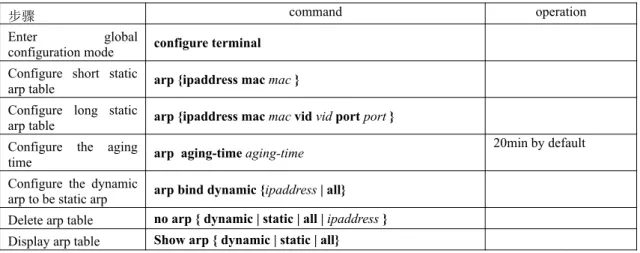
9.2 ARP Configuration...128
9.2.1 ARP Table Configuration...128
9.2.2 ARP peer... 128
9.2.3 ARP overwrite... 129
9.2.4 Linkup gratuitous-arp...129
9.2.5 Arp-reply-repeat...129
9.2.7 ARP - Proxy... 130
10. Mirroring... 132
10.1 Port Mirroring... 132
10.1.1 Configure Port Mirroring...132
10.1.2 Configuration Example for Port Mirror...132
10.2 RSPAN... 133
10.2.1 Configure Remote Port Mirror...133
10.2.2 Configuration Example for Remote Port Mirroring...134
10.3 Flow Mirror... 135
10.3.1 Configure Flow Mirror...135
10.3.2 Configuration Example for Flow Mirror...135
11. SNMP Login Management...136
11.1 SNMP Overview... 136
11.2 Configuring the Basic Parameters...136
11.3 Configure the Community Name...137
11.4 Configure the Group...137
11.5 Configure the User... 138
11.6 Configure the Views...138
11.7 Configure SNMP Notification...138
11.8 Configure Engine ID... 139
11.9 Configuration Example for Snmp...139
12. DHCP Configuration...141
12.1 DHCP Introduction... 141
12.1.1 IP Address Assignment Policy...141
12.1.2 IP Address Dynamic Acquisition Process...141
12.1.3 DHCP Message Structure...143
12.2 DHCP Server Configuration...144
12.2.1 Applicable Environment of the DHCP Server...144
12.2.2 DHCP Address Pool...144
12.2.3 Configure Address Pool...144
12.2.4 Configure DHCP Server to Assign the DNS Server Address...145
12.2.5 Configure DHCP Server to Assign WINS Server Address...146
12.2.6 Configure DHCP Self-defined Options...146
12.2.7 Configure DHCP Server to Support option 60...146
12.2.8 Enable DHCP server Function...147
12.2.9 DHCP Server Display and Maintenance...147
12.3 DHCP Relay Configuration...147
12.3.1 Applicable Environment of DHCP Relay...147
12.3.2 Basic Principles of DHCP Relay...148
12.3.3 The Processing of DHCP Relay for DHCP Message...148
12.3.4 Configure DHCP Server Group...148
12.3.5 Configure DHCP Relay Agent to Support option 60...149
12.3.6 Enable the DHCP Relay Function...149
12.3.7 DHCP Relay Display and Maintenance...150
12.4 DHCP Snooping Configuration...150
12.4.1 DHCP-Snooping Overview...150
12.4.2 DHCP Snooping Configuration...150
12.4.3 Configure Link-Down Operation...151
12.4.4 Configure Max Clients Number...151
12.4.5 IP-Source-Guard Overview...152
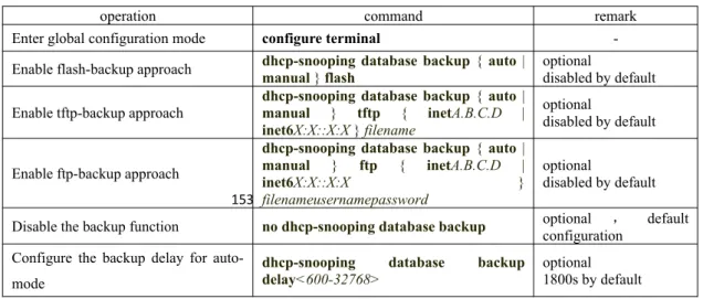
12.4.6 Backup the User Table...152
12.4.7 Display and Maintenance for DHCP Snooping...153
12.4.8 Configuration Example for DHCP Snooping...154
12.5.1 Configure DHCP Option82...156
12.5.2 DHCP Option82Display and Maintenance...156
12.6 DHCPv6 Snooping Overview...157
12.6.1 Configure DHCPv6 Snooping...157
12.6.2 Configure the Port Operation When Link Down...157
12.6.3 Limit DHCPv6-Client Number Accessed to the Port...157
12.6.4 Configure IPv6-Source-Guard...158
12.6.5 DHCPv6 Snooping Display and Maintenance...158
12.6.6 Configuration Example for DHCPv6 Snooping...159
12.7 DHCPv6 Option 18 and DHCPv6 Option 37...160
12.7.1 DHCPv6 Option18 Configuration and Display...160
12.7.2 DHCPv6 Option37 Configuration and Display...160
12.7.3 Configuration Examples of DHCPv6 Option18 and DHCPv6 Option37...161
13. ACL Configuration... 162
13.1 ACL Matching Order...162
13.1.1 Configuration Example for ACL Matching Order...162
13.2 Standard ACLs... 163
13.2.1 Configuration Example...164
13.3 Extended ACL... 164
13.3.1 Configuration Example for Extended ACL...166
13.4 Layer2 ACL... 166
13.4.1 Configuration Example for Layer2 ACL...167
13.5 Time Range... 168
13.5.1 Configuration Examples...168
13.6 Activate ACL... 169
13.6.1 Configuration Examples for ACL activating...169
13.7 ACL Display and Debug...171
14. QACL Configuration...172
14.1 QACL Related Concept...172
14.2 Configure Traffic Speed Limit...174
14.3 Configure Two Rate Three Color Marker...175
14.4 Configure Message Redirection...176
14.5 Configure Message Copy to CPU...176
14.6 Configure Precedence Marker...177
14.7 Configure Traffic Statistic...177
14.8 Configure VLAN Rewrite...177
14.9 Configure VLAN Insert...177
14.10 QACL Display and Maintenance...178
14.11 QACL Configuration Example...178
15. Cos Control... 180
15.1 CoS Control Function Overview...180
15.2 CoS Control Configuration...181
15.2.1 Configure CoS Control...181
15.2.2 Configure 802.1p and Hardware Queue Mapping...181
15.2.3 Configure DSCP and 802.1P Mapping...182
15.3 COS Control Configuration Example...182
16. Forward Control... 185
16.1 bandwidth-control Function...185
16.1.1 Configure Bandwidth Limit for Port...185
16.1.2 Bandwidth Limit Display and Maintenance...185
16.1.3 Bandwidth-control Configuration Example...185
16.2 Storm-control Function...186
16.2.1 Storm-control Configuration...186
16.2.3 Storm-control Configuration Example...187
17. Attack Protection... 189
17.1 Anti-DDOS Attack Function...189
17.1.1 Anti-TTL Attack...189
17.1.2 Configure Anti-IP Fragment Attack...189
17.1.3 Configuration Example...189 17.2 CPU-car Function... 191 17.2.1 Configure Cpu-car...191 17.2.2 Configuration Example...191 17.3 Shutdown-Control Function...194 17.3.1 Enable/disable Shutdown-Control...194
17.3.2 Configure Recovery Mode...194
17.3.3 Manually Restore Shutdown Port...195
17.3.4 Configuration Example...195
17.4 Anti-DHCP Attack... 197
17.4.1 Enable/disable Anti-DHCP...197
17.4.2 Configure Processing Policy...197
17.4.3 Configure Rate Threshold...198
17.4.4 Configure Recovery Function...198
17.4.5 Configure Trusted Port...198
17.4.6 Configuration Example...199
17.5 ARP Spoofing and Flood Attack...200
17.5.1 Overview for ARP Spoofing...200
17.5.2 Overview for ARP Flooding Attack...201
17.5.3 Anti-Spoofing Configuration...201
17.5.4 Host Protection Configuration...202
17.5.5 Configure Source-MAC Consistency Inspection...202
17.5.6 Configure Anti-Gateway-Spoofing for Layer-3 Equipment...202
17.5.7 Configure Anti-Gateway-Spoofing for Layer-2 Equipment...203
17.5.8 Configure the Trust Port...203
17.5.9 Anti-Flood Attack Configuration...203
17.5.10 Display and Maintain...204
17.5.11 Example for Anti- ARP Spoofing Configuration...204
18. Single Spanning Tree...207
18.1 STP Introduction... 207
18.1.1 STP Practical Application...207
18.1.2 Bridge Protocol Data Unit...207
18.1.3 Basic Concepts of STP...207
18.2 RSTP Introduction... 208
18.3 Configure STP/RSTP... 208
18.3.1 Enable the Spanning Tree...208
18.3.2 Set the Bridge Priority of the OLT...208
18.3.3 Configure Time Parameter...208
18.3.4 Configure Path Cost of Port...209
18.3.5 Configure the Priority of Port...209
18.3.6 Configure Mcheck Function...210
18.3.7 Configure Point-to-Point Link...210
18.3.8 Configure Port to Edge Port...210
18.3.9 Set Port to Send the Maximum Rate of BPDU...210
18.3.10 Configure Root Protection Function of a Port...211
18.3.11 Configure Loop-guard Function...211
18.3.12 Configure Bpdu-guard Function...211
18.3.13 Configure bpdu-filter Function...212
18.3.15 Discard-BPDU Function...212
18.3.16 Display and Maintenance...213
18.3.17 RSTP Configuration Example...213
19. Multiple Spanning Tree Configuration...217
19.1 MSTP Overview... 217
19.1.1 Bridge Protocol Data Unit...218
19.1.2 Basic Concepts in MSTP...218
19.1.3 Role of Port... 220
19.2 MSTP Election Calculation...223
19.2.1 MSTP Protocol Message...223
19.2.2 CIST Priority Vector...225
19.2.3 MSTI Priority Vecor...226
19.2.4 MSTP Election Process...226
19.2.5 CIST Role Selection...226
19.2.6 MSTI Role Selection...228
19.2.7 Topology Stable State...229
19.2.8 Topology Change...230
19.2.9 MST and SST Compatibility...230
19.3 Configure MSTP... 231
19.3.1 Start MSTP...231
19.3.2 Configure the MSTP Timer Parameter Value...231
19.3.3 Configure the MSTP Configuration Identifier...232
19.3.4 Configure MSTP Bridge Priority...232
19.3.5 Configure the Boundary Port Status of a Port...232
19.3.6 Configure the Link Type of Port...233
19.3.7 Configure the Path Cost of Port...233
19.3.8 Configure Port Priority...234
19.3.9 Configure Root Protection of Port...234
19.3.10 Configure the Digest Snooping Function...234
19.3.11 Configure loop-guard Function...235
19.3.12 Configure bpdu guard Function...235
19.3.13 Configure bpdu-filter Function...236
19.3.14 Configure mcheck Function...236
19.3.15 Enable / Disable MSTP Instance...236
19.3.16 MSTP Display and Maintenance...237
19.3.17 MSTP Configuration Example...237
20. GSTP... 247
20.1 GSTP Function Introduction...247
20.2 GSTP Configuration...247
20.2.1 Enable Configuration...247
20.2.2 Configure the Processing Policy...248
20.2.3 Configure the Recovery Timer...248
20.2.4 Configure the Detection Period...248
20.2.5 GSTP Configuration Example...249
21. PVST Configuration...251
21.1 PVST Introduction... 251
21.2 PVST Configuration...251
21.2.1 Configure PVST Mode...251
21.2.2 Configure PVST Timer Parameter Value...251
21.2.3 Configure VLAN and Instance Mapping...252
21.2.4 Configure PVST Instance Priority...252
21.2.5 Configure the Path Cost of Port...253
21.2.6 Configure the Port Priority...253
21.3 PVST Configuration Example...253
22. ERRP Configuration...257
22.1 ERRP Function Introduction...257
22.1.1 Concept Introduction...257
22.1.2 Protocol Message...259
22.1.3 Operate Principle...260
22.1.4 Multi-loop Intersection Processing...261
22.2 ERRP Configuration...262
22.2.1 Enable/disable ERRP...262
22.2.2 Configuration Domain...262
22.2.3 Configure Control VLAN...262
22.2.4 Configure the Ring...263
22.2.5 Configure Node Role...263
22.2.6 Configure Port Role...264
22.2.7 Configure Work Mode...264
22.2.8 Configure Query Solicit...264
22.2.9 Configure Time Parameter...265
22.2.10 Configure the Topology Discovery Function...265
22.2.11 Clear Protocol Message Statistic...265
22.3 ERRP Configuration Example...266
23. ERPS Configuration...270
23.1 ERPS... 270
23.1.1 ERPS Overview...270
23.1.2 ERPS Basic Conception...270
23.1.3 ERPS Ring Protection Mechanism...271
23.2 ERPS Configuration...273
23.2.1 Enable ERPS... 273
23.2.2 ERPS Configuration Example...273
23.2.3 Configure Connectivity Detection of ERRP Link...274
23.2.4 Configure ERPS Related Timers...274
23.2.5 ERPS Display and Maintenance...275
23.3 ERPS Configuration Example...276
23.3.1 Demand and networking...276
23.3.2 Configuration on ERPS Ring Network Protection...276
23.3.3 Result Validation...278
24. Static Routing Configuration...278
24.1 Static Routing Overview...278
24.2 Detailed Configuration of Static Routing Table...278
24.2.1 Add/Delete Static Routing Table...278
24.2.2 Add/ Delete Static Routing Backup Table...279
24.2.3 Display Routing Table Information...279
24.3 Configuration Example...280
25. RIP Configuration... 281
25.1 RIP Overview... 281
25.2 RIP Configuration... 282
25.2.1 Enable /Disable RIP Mode...282
25.2.2 Specify the IP Network Segment to Run RIP...282
25.2.3 Specify the RIP Operation State for an Interface...283
25.2.4 Specify the RIP Version for an Interface...283
25.2.5 Enable the Host Route Function...284
25.2.6 Enable the Route Aggregation Function...284
25.2.7 Configure RIP Packet Authentication...284
25.2.8 Configure Split Horizon...285
25.2.10 Define a Prefix List...286
25.2.11 Configure Route Redistribution...286
25.2.12 Configure External Route Aggregation...287
25.2.13 Configure Route Filtering...287
25.2.14 Display RIP Configurations...287
25.3 Examples... 288
25.3.1 Configuration Examples...288
25.3.2 Application Examples...289
26. OSPF Configuration...290
26.1 OSPF Overview... 290
26.2 OSPF Detailed Configuration...291
26.2.1 Enable/Disable OSPF Configuration...291
26.2.2 Configure the ID of a Router...292
26.2.3 Specify an Interface and Area ID...292
26.2.4 Configure the Authentication Type for an Area...293
26.2.5 Set a Password for Packet Authentication...293
26.2.6 Configure OSPF Interface Type...293
26.2.7 OSPF Area Related Configuration...296
26.3 Configuration Example...298 26.4 Application Example...299 27. BGP Configuration...304 27.1 BGP Overview... 304 27.2 BGP Configuration...309 27.2.1 Basic Configuration...309
27.2.2 Configure the BGP Neighbor...310
27.2.3 Configure the Timer...310
27.2.4 Import the Routing...311
27.2.5 Configure Routing Aggregation...311
27.2.6 Configure the Local Priority...312
27.2.7 Configure MED...312
27.2.8 Configure Routing Strategy...313
27.2.9 Check BGP Information...314
27.3 Example for BGP Configuration...314
28. Other Routing Configurations...316
28.1 IP-Def-CPU Overview...316
28.1.1 Configure IP-Def-CPU...316
28.1.2 Configuration Example...316
28.2 ECMP... 317
28.2.1 ECMP Configuration...317
28.2.2 Configuration Example for ECMP...318
28.3 URPF... 319
28.3.1 URPF Configuration...319
28.3.2 URPF Configuration Example...319
29. VRRP Configuration... 322
29.1 VRRP Introduction...322
29.2 VRRP Basic Configuration...323
29.2.1 Configure the Virtual IP of the VRRP Backup Group...323
29.2.2 Configure the Priority of the OLT in the VRRP group...324
29.2.3 Configure the Work State of the OLT in the VRRP Group...324
29.2.4 Configure the Preemption Delay of the Backup Group...325
29.2.5 Configure the OLT Advertisement Interval in the Backup Group...325
29.2.6 Configure VRRP Track Function...326
29.2.7 Configure VRRP Ping Function...326
29.3 VRRP Configuration Example...327 30. 802.1X Configuration...336 30.1 802.1x Overview...336 30.1.1 802.1x Authentication...336 30.1.2 802.1x Authentication Process...337 30.2 802.1X Configuration...339 30.2.1 Configure EAP... 339 30.2.2 Enable 802.1x...340
30.2.3 Configure 802.1x Parameters for a Port...340
30.2.4 Re-authentication Configuration...341
30.2.5 Watch Function Configuration...341
30.2.6 Configure User Features...341
30.2.7 Configure Host Mode Based on Port Authentication Mode...342
30.2.8 Configure Guest VLAN...342
30.2.9 Configure Default-active-vlan...343
30.2.10 Configure Radius vlan...343
30.2.11 Configure EAPOL Transmission...344
30.2.12 Security Channel Configuration...344
30.2.13 Issued ACL...344
30.2.14 Dot1x Display and Maintenance...345
30.3 Configuration Example...346 30.3.1 Networking Requirements...346 30.3.2 Configuration steps...347 30.3.3 Result Validation...347 31. RADIUS Configuration...348 31.1 Radius Overview...348 31.1.1 AAA Overview...348 31.1.2 AAA Realization...348 31.1.3 RADIUS Overview...349 31.2 RADIUS Configuration...349
31.2.1 RADIUS Server Configuration...349
31.2.2 Radius Master Server & Radius Slave Server Shift...350
31.2.3 Configure Local User...351
31.2.4 Configure Domain...351
31.2.5 RADIUS Attribute Configuration...352
31.2.6 RADIUS Display and Maintenance...353
31.3 RADIUS Configuration Example...353
31.3.1 Configure the networking and requirements...353
31.3.2 Configuration steps...354
31.3.3 Result Validation...357
32. Port Security Configuration...359
32.1 Port Security Overview...359
32.2 Port Security Configuration...360
32.3 Port Security Configuration Example...361
33. SNTP Client... 363
33.1 SNTP Function Introduction...363
33.2 Configure the SNTP Client...363
33.2.1 Enable/disable SNTP Client...363
33.2.2 Configure the Work Mode of the Sntp Client...364
33.2.3 Configure SNTP Server Address...364
33.2.4 Modify the Broadcast Transmission Delay...364
33.2.5 Configure Multicast TTL...364
33.2.6 Configure the Polling Interval...365
33.2.8 Configure the Client Daylight Saving Time...365
33.2.9 Configure Legacy Server List...366
33.2.10 Configure Authentication...366
33.2.11 Manual Calibration of the System Clock...367
33.2.12 SNTP Client Configuration Esample...367
34. Link Backup Function...371
34.1 Flex Links Function... 371
34.1.1 Flex Links Introduction...371
34.1.2 Configure Flex Links Group...374
34.1.3 Configure Flex Links Preemption Mode...374
34.1.4 Configure the Delay Time for Priority Preemption of Flex Links...375
34.1.5 Configure Flex Links MMU Function...375
34.1.6 FLex Links Display and Maintenance...375
34.2 Monitor Link Function... 376
34.2.1 Monitor Link Introduction...376
34.2.2 Configure Monitor Link Group...379
34.2.3 Monitor Link Display and Maintenance...379
34.2.4 Flex Links & Monitor Link Configuration Example...380
34.3 VPRB Function... 385 34.3.1 VPRB Function Introduction...385 34.3.2 Configure Basic MSTP...385 34.3.3 Configure vprb...385 34.3.4 Configuration Example...386 35. PPPoE Plus... 388
35.1 PPPoE Plus Function Overview...388
35.2 PPPoE Plus Configuration...388
35.2.1 Enable/disable PPPoE Plus...388
35.2.2 Configure the Option Processing Strategy...389
35.2.3 Discard padi/pado Packet...389
35.2.4 Configure the Packet Type...390
35.2.5 Configuration Example...391
36. File Upload and Download...393
36.1 File Download Function...393
36.1.1 Configuration file download...393
36.1.2 File Download Configuration Example...394
36.2 File Upload Function...395
36.2.1 Configuration File Upload...395
36.2.2 File Upload Configuration Example...396
37. Configure Decompilation...397
37.1 Overview for Decompilation Configuration...397
37.2 Basic Commands for Decompilation...397
37.3 Configure Switchover of File Execution Mode...398
37.3.1 Decompilation Configuration Example...398
38. Utilization Alarm... 400
38.1 Utilization Alarm Function Overview...400
38.2 Configure Utilization Alarm...400
38.2.1 Configure the Port Utilization Alarm...400
38.2.2 Configure the CPU Utilization Alarm...401
38.2.3 Utilization Alarm Configuration Example...401
39. Mail Alarm... 403
39.1 Mail Alarm Function Overview...403
39.2 Configure the Alarm...403
39.3 Mail Alarm Configuration Example...403
40.1 System Log Function Overview...405
40.2 Configure System Log...405
40.2.1 Enable/disable Syslog...405
40.2.2 Configure the Log Serial Number...406
40.2.3 Configure the Timestamp...406
40.2.4 Output to the Terminal...406
40.2.5 Output to Buffer...407
40.2.6 Output to Flash... 408
40.2.7 Output to External Server...408
40.2.8 Output to the SNMP Agent...409
40.2.9 Debugging Function...409
40.2.10 Syslog Configuration Example...410
41. System Maintenance...412
41.1 View the System Status...412
41.2 Set the OLT Host Name...412
41.3 Set the System Clock...413
41.4 Network Connection Test Command...413
41.5 Route Tracking Command...414
41.6 Banner... 414
41.7 The Number of Lines Displayed When Viewing Information...415
41.8 Restart OLT... 415
41.8.1 Command to Restart OLT Immediately...415
41.8.2 Restart the OLT Periodically...416
42. sFlow Configuration...418
42.1 sFlow Introduction... 418
42.2 sFlow Configuration...418
42.2.1 Set the sFlow Agent IP...418
42.2.2 Configure sflow Collector...419
42.2.3 Configure the sflow sampling-rate...419
42.2.4 Configure the sflow flow max-header...420
42.2.5 Configure sflow flow Collector...421
42.2.6 Configure sflow counter Interval...421
42.2.7 Configure sflow Counter Collector...421
42.2.8 The Command of show sflow...422
42.3 Example... 422 43. CFM Configuration...424 43.1 CFM Introduction... 424 43.1.1 CFM Concept... 424 43.1.2 CFM Main Functions...425 43.1.3 Configure CFM...425 43.2 CFM Configuration...426 43.2.1 Configure the MD...426
43.2.2 Configure the Maintenance Domain Name and Level...426
43.2.3 Configure the Maintenance Association...426
43.2.4 Configure the Maintenance Association Name and Associated VLAN...427
43.2.5 Configure the MEP...427
43.2.6 Configure the Remote MEP...427
43.2.7 Configure the MIP...428
43.2.8 Configure the Continuity Check Function...428
43.2.9 Configure the Loopback Function...428
43.2.10 Configure the Link Tracking Function...429
43.2.11 Y.1731 Frame Loss Rate Detection Function...429
43.2.12 Y.1731 Frame Delay Measurement Function...429
43.3 Configuration Example...430
44. EFM Configuration... 431
44.1 EFM Introduction...431
44.1.1 EFM Main Function...431
44.1.2 EFM Protocol Packet...432
44.2 Configure EFM... 432
44.2.1 EFM Basic Configuration...432
44.2.2 EFM Timer Parameter Configuration...433
44.2.3 Configure the Remote Fault Detection Function...433
44.2.4 Configure the Link Monitoring Function...434
44.2.5 Enable Remote Loopback...435
44.2.6 Reject Remote Loopback Request From Remote Side...435
44.2.7 Initiate the Remote Loopback Request...435
44.2.8 Enable the Remote MIB Variable Acquisition Function...436
44.2.9 Initiate the Remote MIB Variable Acquisition Request...436
44.2.10 EFM Display and Maintenance...436
44.3 Configuration Example...437 45. BFD... 438 45.1 BFD Function Overview...438 45.2 BFD Configuration...439 45.2.1 Enable/Disable BFD...439 45.2.2 Apply to OSPF...439
45.2.3 Configure the Session Mode...439
45.2.4 Configure the Query Mode...440
45.2.5 Configure Time Parameters...440
45.2.6 Information Display and Maintenance...440
45.3 BFD Configuration Example...441
46. LLDP... 443
46.1 LLDP Function Overview...443
46.2 LLDP Configuration...443
46.2.1 Enable/disable LLDP...443
46.2.2 Configure the Working Mode...443
46.2.3 Configure Time Parameters...444
46.2.4 Configure the Management Address...444
46.2.5 Information Display and Maintenance...445
1
1. Login OLT
1.1 Overview for Login OLT
System supports multiple ways to login OLT: serial port, Telnet, SSH, Web browser, and netmanager software.
1.2 Login OLT
1.2.1
Login OLT via Serial Port
Login via the console port is the most basic way to login to the device.
By default, the user can login to the device directly via the serial port. The baud rate of the OLT is 115200bit/s.
Refer to the following for specific:
(1) As shown below, use a dedicated serial cable (usually the product comes with a serial cable), insert the DB-9 connector of the serial cable into the 9-pin serial port of the PC, and then insert the RJ-45 connector into the console port of the device.
Connect the PC with the DUT via the serial cable
(2) Run the terminal software which supports serial transmission, such as HyperTerminal of SecureCRT/Windows XP. Parameter requirements: baud rate is "115200", the data bit is "8", parity is "no", stop bit is "1", the data flow control is "no", terminal emulation is "automatic detection", as shown in the figure below.
2
Serial connection parameters
(3) Follow the prompts to key in the user name and password and then enter the OLT. The default user name is admin, and the default password is 123456. It is recommended that you modify the initial password after you login to the device and remember the modified password (refer to User Management for how to modify the password).
1.2.2
Login OLT via Telnet
(1) Configure equipment to be Telnet server
Login to the OLT through telnet, and the device acts as telnet-server. By default, the Telnet-server function is enabled. However, the device does not have a default IP address. That is, the client cannot login to the device by default. So before use telnet to login OLT, you need to configure the OLT IP via the serial port to ensure the communication between pc and DUT is normal.
Telnet-Server Configuration
operation command remark
Enter global
configuration mode
configure terminal
-Enable Telnet-server telnet enable optional
Disable Telnet-server telnet disable optional
Limit the numbers of login users
telnet limitvalue optional
Display the limit value of login users
show telnet limit optional
Display login client show telnet client optional
--3
Force users to go offline
stop telnet client [ all | user-id ] optional Client timeout exit
function
[no]timeout optional
Client timeout
configuration
timeout value optional
Note:
As telnet server, DUT will disconnect automatically if the client who login doesn't have any operations for a long time. That is, timeout out. The function is enabled by default, and the timeout value is 20m.
(2) Configure DUT acts as Telnet-client to login other device
The user has successfully logged in to the device and wants to login another device from telnet. Acting as Telnet-client, DUT should ensure the communication between telnet-client and telnet-server is normal when telnet to server.
Telnet-Client Configuration
operation command remark
Enter privilege configuration mode
-
-telnet login server telnet[6] server-ip [ port-number ] [ /localecho ] required
Enter global
configuration mode
-Timeout exit
function
[no] telnetclient timeout optional
Timeout configuration
telnetclient timeout value optional
Note:
As telnet server, DUT will disconnect automatically if the client who login doesn't have any operations for a long time. That is, timeout out. The function is enabled by default, and the timeout value is 20m.
1.2.3
Login OLT via SSH
The OLT can act as an SSH server but not an SSH client.
By default, the SSH server function is disabled. Therefore, before you login to the device via SSH, you need to login to the device via the console port, and then enable the SSH server and other attributes so asto ensure normal login to the device through SSH.
SSH Configuration
operation command remark
Enter global
configuration mode configure terminal
-Enable/disable ssh [no] ssh required
Display ssh
configuration show ssh optional
Limit the users number [no] ssh limit value optional
Display the number of
the users show ssh limit optional
Enter privilege
-4
Force users to go
offline stop vty [ all | user-id ] optional
Configure the default
key crypto key geneate rsa required
Remove the keyfile crypto key zeroize rsa optional
Activate the key crypto key refresh optional
Download the key from the external key server to this machine
loadkeyfile { public | private } tftp inet[6]server-ip
filename optional
load keyfile { public | private } ftp inet[6]
server-ipfilenameusername passwd optional
Upload the local key to the key server
upload keyfile { public | private } tftp inet[6] server-ip
filename optional
upload keyfile { public | private } ftp inet[6] server-ip
filename username passwd optional
Display keyfile show keyfile{ public | private } optional
Note:
1. If you need to use ssh to login DUT, the simplest operation will be a. Open ssh; 2. Configure the default key; 3. Activate key;
2. The key file and configuration are saved in the flash and do not go into decompilation;
1.2.4
Login OLT via Web
You can log on the OLT via the web. However, the web function is not perfect, so most of the functions cannot be configured on the web. So it is not recommended to manage the OLT in this way.
By default, the function that the OLT acts as the http server is disabled. Before login web, you need to enable the http-server function, and then configure the appropriate IP, to ensure the communication between the client and http server is normal.
WEB login configuration
operation command remark
Enter global
configuration mode
configure terminal required
Enable http-server http enable [porttcp-port] optional
Disable http-server
http disable optional
1.2.5
Manage OLT via Netmanager Software
The OLT supports login management via the NMS software. By default, the snmp-server function is enabled and the default community name can be used. Please refer to snmp user manual for more detailed configurations.
Snmp configuration
operation command remark
Enter global
configuration mode
configure terminal required
5
snmp-server
Note:
1. Some devices do not have the command to configure snmp-server function. Moreover, the system will be automatically enabled when the system is powered on and it cannot be disabled.
2. By default, the iso view contains two communities which are allowed to access: a. Private community with rw authority; b) public community with ro privilege;
1.3
Command Line Interface
1.3.1
Overview for Command Line Interface
System provides a series of command configurations and command line interfaces, and users can configure OLT or manage OLT through command line.
Here are the features of command line interface: Local configuration through Console port. Local/remote configuration through TelNet port.
Configure hierarchical protection command to ban unauthorized users from entering system.
Users can type “?”to get help information at any time
Provide network test command, like ping, to diagnose if the network is normal.
Support FTP, TFTP, Xmodem, making it convenience for client to upload file or download file.
There is no need for users to type entire key words because command line interpreter adopts incomplete matching search method which can handle imprecise search requirement. For example, user can get the interface command by typing interf.
1.3.2
Command Line Mode
Protection command was adopted by command line to ban unauthorized users from entering system. Different command mode corresponds to different configuration. For example, after login, users of any level can enter normal user mode with the permission to check information of system operation; however, administrator can type enable to enter the privilege mode. Under privilege mode, he can enter global mode by typing configure terminal. In the global mode, typing different configuration command corresponds to different command mode. For instance, if you type vlan vlan-list, you will enter in VLAN configuration mode.
Command line provides the following command modes: User Mode
Privileged Mode
Global Configuration Mode
Ethernet Interface Configuration Mode
VLAN Configuration Mode
AAA Configuration Mode
6
Domain Configuration Mode
VLAN Interface Configuration Mode
SuperVLAN Interface Configuration Mode
The features of each command mode and their entrance details are as follow:
Command Line Mode
command line
mode function prompt enter command line exit commandline
User Mode show OLT
running status
OptiWay> connect with OLT, and then input username and password Key inexit to disconnect with OLT Privileged Mode show OLT running status, and then running system
management
OptiWay# Under User Mode, key
in enable
Key inexit to go back to User Mode; Key inquit to disconnectwith OLT Global Configuration Mode configure global
parameters OptiWay(config)# Under Mode, key inPrivileged configure terminal
Key inexit、end to go back to Privileged Mode; Key inquit to disconnectwith OLT Ethernet Interface Configuration Mode configure Ethernet port parameters OptiWay(config-if-ethernet-0/1)# Under Global Configuration Mode, key in interface Ethernet 0/0/1 Key inend to go back to Privileged Mode; Key in exit to go back toGlobal Configuration Mode; Key inquit to disconnectwith OLT VLAN Configuration Mode configure VLAN
parameters OptiWay(config-if-vlan)# Under Global Configuration Mode, key in vlan2 AAA
Configuration
Mode set up the domain OptiWay(config-aaa)#
Under Global Configuration Mode, key in aaa RADIUS Configuration Mode configure RADIUS parameters OptiWay(config-radius-default)# Under AAA configuration mode, key in radius host default
Key in end to go back to Privileged Mode
Key in exit means go back to AAA configuration mode Key in quit to disconnect with OLT Domain Configuration Mode configure domain parameters OptiWay(config-aaa-test.com)# Under AAA configuration mode, key in domain test.com VLAN Interface Configuration Mode configure VLAN
L3 interface OptiWay(config-if-vlanInterface-22)#
Under Global Configuration Mode, key in interface vlan-interface 22
Key inend to go back to Privileged Mode; Key in exit to go back toGlobal Configuration Mode; Key inquit to disconnectwith OLT SuperVLAN Interface Configuration Mode configure SuperVLAN L3 interface OptiWay(config-if-superVLANInterface-1)# Under Global Configuration Mode, key in interface supervlan-interface 1 Key inend to go back to Privileged Mode; Key in exit to go back toGlobal Configuration Mode; Key inquit to disconnectwith OLT
7
1.3.3
Comprehension of Command Syntax
This chapter mainly describes the configuration steps when enter the command line. Please read this chapter and the following chapters for detail information on how to use the command line interface.
The login authentication of OLT system console is mainly for operating user identity verification via the matching recognition of the user's username and password, to allow or deny a user login.
The first step: when the following login prompt shows in the command line interface, Username(1-32 chars):
Please key in the login user name and press the enter button, and then prompt information will be showed:
Password (1-16 chars):
Key in login password, if the password is correct, you can enter the normal user mode, the prompt will be:
OptiWay>
There are two different permissions in the OLT system. One is administrator privilege, and the other is common user permissions. Common users generally can only see the OLT configuration information, without the right to modify. However, the administrator can use the specific commands to manage OLT configuration.
If login as system administrator, then enter privileged user mode from common user mode: OptiWay>enable
OptiWay#
The second step: key in command name
If the command you key in do not require user to input parameter, you can skip to the third step. If the command you key in requires user to input parameter, please continue the following steps:
If the command requires a parameter value, please key in the parameter value. You might have to input keywords when you key in parameter value.
Generally, command-line parameter value specifies the parameter what you need to input. It is a numerical value within a certain scope, or a string, or an IP address. If you have any questions, you can enter "?", then input the correct value according to the prompt. Keywords refer to the operand in command.
If the command requires multiple parameter values, please input keywords and each parameter value according to the command prompt until the prompt information "< enter >" appears. At that time, what you should do is just to press the “<enter>” button to end this command.
The third step: key in the complete command, and then press the enter button. For example:
! The user does not need to enter parameters OptiWay#quit
“quit” is a command without parameter. “quit” is the command name, pressing the enter button is to execute the command after typing this command.
!Users should key in parameters OptiWay(config)#vlan 3
“vlan 3”is a command that with parameter and key word. “vlan” is the Key word, and “3” is the parameter value.
8
1.3.4
Syntax Help
There is a build-in syntax help in the command line interface. If you are not sure of the command syntax, you can key in "?" in any command mode or get all commands and their brief description of this command mode via "help" command; key in the command string you want, with "?" following. Key in "?" after the space character, then the command line will list all the keywords begin with the string you typed. If the Location of "?" is a keyword, the command line will list all the key words and its brief description; if the Location of "?" is a parameter, the command line will list the description of relevant parameter. You can key in commands according to the reminder until the prompt command shows with "< enter >", at that time, what you should do is just to input carriage return for the command execution.
For example:
1.
key in “?”under the privilege mode
OptiWay#?System mode commands: cls clear screen
help description of the interactive help ping ping command
quit disconnect from switch and quit ……
2.
key in“?”closely after keywords
OptiWay(config)#interf?interface
3.
input “?” after command string and the space character
OptiWay(config)#spanning-tree ?forward-time config switch delaytime hello-time config switch hellotime max-age config switch max agingtime priority config switch priority
<enter> The command end.
4.
Parameters range/ parameters format
OptiWay(config)#spanning-tree forward-time ? INTEGER<4-30> switch delaytime: <4-30>(second) 5.
Ending prompt command line
OptiWay(config)#spanning-tree ? <enter> The command end.
Under the privilege configuration mode, the above help information can be displayed in English and Chinese switching by executing the following command:
9
1.3.5
History Command
The commands entered by users can be automatically saved by the command line interface and you can invoke or re-execute them at any time later. History command buffer is defaulted as 100. That is, the command line interface can store 100 history commands at the most for each user. You can access the last command by input “Ctrl+P”; you can access the next command by input “Ctrl+N”
1.3.6
Types of Command Parameters
There are 5 types of parameters:
Integer
The two numbers in the angle brackets (<>), connecting by hyphen (-) mean this parameter is the integer between these two numbers.
For example: INTEGER<1-10> means user can key in any integer which can be more than or equal to 1 and less than or equal to 10, such as 8.
IP Address
A.B.C.D means an IP address.
For example: 192.168.0.100 is a valid IP address.
MAC Address
H:H:H:H:H:H means a MAC address. If a multicast MAC address is needed, there would be corresponded prompt.
For example: 01:02:03:04:05:06 is a valid MAC address.
Interface List
Interface list is prompt as STRING<3-4>. Port parameter interface-num consists of port type and port number. Port type is ethernet and port number is device/slot-num/port-num. device means stack device, and the value is 0. slot-num means slot number, data range is 0-1; port-num is the port number in the slot, data range is 1 -12. Port parameter interface-list means multiple ports. Serial ports of the same type can be connected by "to", but the port number behind the “to” must be larger than the one in the front, and this argument only can be repeated up to 3 times. The special declaration of interface parameter interface list will be displayed in the command.
For example: show spanning-tree interface ethernet 0/0/1 ethernet 0/0/3 to ethernet 0/0/5
means showing the spanning-tree information about interface ethernet 0/0/1, ethernet 0/0/3, ethernet 0/0/4 and ethernet 0/5.
String
The prompt STRING<1-19> means a character string which is in the length of1 to 19. Enter “?” to check the parameter description of this command.
1.3.7
Error Message
prompt Explanation Causes Solution
Incomplete command The command input is incomplete and the system cannot recognize it
There may be more than one command in the system, the system cannot recognize the abbreviation; command is not finished, need to add
Enter "?" to view the available commands or enter the complete command
10
other parameters Invalid parameter Invalid parameter Parameter out of
range Check therange of parameters and re-enter Unrecognized command You enter the wrong command, and the
system cannot recognize Misspelledentered a commandor that does not exist
Enter "?" to view the available commands
11
2. Equipment Management
2.1 Overview for User Management Functions
Login the OLT to perform management configuration, and it must be authentication & authorization to prevent illegal user accessing and unauthorized accessing. User management is the management on user authentication and authorization. If the authentication and authorization of the user is performed by the OLT system itself, it is called local authentication. If the authentication and authorization of a user is performed by a system other than the OLT (usually called an authentication server such as radius-server), it is called remote authentication. The user management content in this chapter refers to local authentication.
The OLT has three types of permissions: a. ordinary user
Ordinary users have the lowest privilege level. They can only enter the execution configuration mode, view system configuration information. However, they cannot make other configurations, and cannot modify their own passwords.
b. administrator user
Administrators not only have the rights of ordinary users, but also can configure the OLT, modify their own passwords. However, they cannot create users and modify the password of other users.
c. super user
The super user is the default user of the system: admin. The system has only one super user and cannot be deleted. Super user has all permissions: it can do any OLT configurations, create users, modify its own password and other users’ passwords, delete the users and so forth. The default password for the admin user is 123456.Unless otherwise specified, all the configurations in this user manual are logged in as admin.
2.1.1
User Management Configuration
The system can create up to 15 users. After the super administrator account successfully login to the device, you can add new users, modify user passwords, modify user rights, delete accounts, limit the login methods and so forth. Ordinary users cannot modify their own passwords. Administrators can modify their own passwords, but they cannot modify other users' passwords. Super administrators can modify any user's password. Moreover, you can view the user’s configurations under all modes.
Permissions: 0-1 for ordinary user, 2-15 for administrator user. Super user (admin), no configuration is required. If you do not enter a permission value when you create a user, the system will automatically assign it with normal permissions.
By default, the user can login via serial port, ssh, telnet, web terminal; Up to five users are allowed to be online at the same time.
User Management Configuration
operation command remark
Enter global
configuration mode configure terminal required
Create users username username privilege pri-value password { 0|7 } password optional The user password is
saved in cipher text service password-encryption Modify the user
12
Modify the user permissions
username usernameprivilegenew-pripassword { 0|7 } password optional
Delete user no usernameusername optional
Configure the login mode
username username terminal{ all | console | ssh | telnet | web |
none } optional
Configure the maximum number of
online users username online-max value optional
Display the users
configuration show username [username] optional
Display the online users show users optional Enter privilege configuration mode --Force users to go offline
stop {username |vty [ all | user-id ] } optional Configure the timeout
value [no]timeoutvalue optional
Note:
When you create a user, the password type is divided into 0 and 7, 0 means that the password is in plain text, 7 means that the password is cipher text. Therefore, when you create a user, the password type must be 0. When you configure service password-encryption, the password configured in plain text becomes decrypted in decompilation, and the decrypted password type will change into 7.
For example:
Create user test, and password is 123, and save the password in plain text OptiWay(config)#username test privilege 0 password 0 123
Add user successfully.
OptiWay(config)#show running-config oam ![OAM]
username test privilege 0 password 0 123 ipaddress 192.168.1.1 255.255.255.0 0.0.0.0 Save the user password in cipher text
OptiWay(config)#service password-encryption OptiWay(config)#sh running-config oam ![OAM]
service password-encryption
username test privilege 0 password 7 884863d2 ipaddress 192.168.1.1 255.255.255.0 0.0.0.0
By saving the user password in cipher text, you can reduce the risk of password leakage. 2.1.2
Silence Mechanism
System silence mechanism: If the times of consecutive login failures exceed the allowable value, the user is not allowed to try to log in for a certain period of time. The function is disabled by default, and the configuration for times of failed login attempts is enabled.
Silence Mechanism
operation command remark
Enter global
configuration mode configure terminal required
Configure the times of consecutive login
failures [no] username failmax
13
Configure the silent
time username silent-timevalue optional Display the silent
configurations show username silent optional
2.2 Second-tier Password Authentication
2.2.1
Overview for Second-tier Password Authentication
Normally, the normal users can only enter the execution mode and they cannot enter other configuration modes. Moreover, normal users can only view the configurations information, and they cannot modify the configurations. Second-tier password authentication provides the mechanism to enhance the authority of normal users, if the normal users pass second-tier password authentication, it indicates that normal users have administrator privileges, that is, the normal users can have the authority to carry out other operations.
Second-tier password authentication includes local authentication and remote authentication. If user management uses local authentication, the second-tier password authentication also uses local authentication. Similarly, if user management uses remote authentication, the second-tier password authentication also uses remote authentication. User management and the password authentication use the same authentication server.
2.2.2
Configure the Second-tier Password Authentication
The second-tier password authentication function is disabled by default. If the local user (privilege level 0-1) logs in to the OLT and tries to enter the privileged mode, the system prompts for the password. Enter the password of the secondary password, and then the authentication succeeds. If you are using remote authentication, when an ordinary user (privilege level 0-1) logs in to the OLT and tries to enter privileged mode, the OLT system automatically uses the configured username and password of second-tier password authentication to perform the authentication. If the authentication passes, the second-tier password authentication is considered successful.
When using the remote authentication, please refer to the User Manual on Remote Authentication
for the configuration of the authentication server.
Configure the Second-tier Password Authentication
operation command remark
Enter global configuration
mode configure terminal required
Enable/disable the function [no] username privilege-auth required Configure the password of
second-tier password
authentication username change-privilege-pwd { 0 | 7 } password required Configure the username of
second-tier password authentication
[no] username privilege-auth-remote-user username required Display the configuration of
second-tier password authentication
show username privilege-auth optional
Note:
If the password is selected as 0, it indicates that the password is in plain text. If you select 7, the password is cipher text. You must use the corresponding plain text for authentication.
14
2.2.3
Configuration Example for Second-tier Password Authentication
1. Network requirementsNormal users login to the OLT via the serial port terminal and have the administrator privileges after pass the secondary password authentication.
2. Configuration steps
# Use admin to login, and then create normal user: test/test OptiWay(config)#username test privilege 0 password 0 test
#If second-tier password authentication is not configured, log in as a normal user OptiWay(config)#quit
Username:test
Password:**** (The password that was set when the user was created: test) #After successful login, tried to enter privileged mode, but failed;
OptiWay>en OptiWay>en
# using the admin to login so as to configure the related parameters of second-tier password authentication
# enable second-tier password authentication OptiWay(config)#username privilege-auth
# Configure the username of second-tier password authentication OptiWay(config)#username privilege-auth-remote-user testtest
# Configure the password of second-tier password authentication (When a user enters privileged mode, the password is required)
OptiWay(config)#username change-privilege-pwd 0 123456
Please input your login password : **** (Check if you have configuration privileges) Change password successfully.
# Exit, and then use test/test(normal user) to login again OptiWay(config)#quit
Username:test
Password:**** (The password that was set when the user was created: test)
# login successfully, enter privilege configuration mode, and then you are prompted to enter a password
OptiWay>
# enter the wrong second-tier password: test, the system prompts the password to be wrong OptiWay>enable
Please input password : **** ((enter the wrong second-tier password: test) Password is error.
OptiWay>
# Enter the correct second-tier password: 123456, successfully authenticated; and then enter privilege configuration mode and global configuration mode, you can configure other parameters. OptiWay>enable
Please input password : ****** (enter the password of second-tier password authentication: 123456)
OptiWay#configure terminal OptiWay(config)#
15
2.3 Remote Authentication
2.3.1
Overview for Remote Authentication
User information can be saved in the database of the OLT system or saved to an external server, known as the authentication server, such as radius-server, tacacs +. The user information is stored on the local OLT. When the user logs in, the OLT can complete the authentication, which is called local authentication. If the user logs in, the OLT cannot complete the authentication, and must authenticate via the server. This is called remote authentication. When using remote authentication, ensure that the communication between the OLT and the authentication server is normal and that the user who logs in is existent on the authentication server.
2.3.2
Configure the Authentication Mode
The local authentication and remote authentication are used for the OLT system authentication, and the local authentication is used by default. The remote authentication supports Radius authentication and Tacacs + authentication. Remote authentication and local authentication can be used in combination, and the remote authentication will take precedence at that time. Moreover, local authentication is attempted only when remote authentication fails.
Configure the Authentication Mode
operation command remark
Enter global configuration
mode configure terminal required
Configure to use local
authentication muser local
Optional; default configurations Configure to use RADIUS
remote authentication muser radius radius-name { pap | chap } [[ account ] local ] optional Configure to use tacasc+
remote authentication muser tacacs+ [ [author] [account] [command-account] [local] ] optional Display authentication
configurations show muser optional
2.3.3
Configure Radius Remote Authentication
Configuration of Radius Remote Authenticationoperation command remark
Enter global configuration
mode configure terminal required
Configure to use RADIUS
remote authentication muser radius radius-name { pap | chap } [[ account ] local ] required Display authentication
configurations show muser optional
Radius Server Configuration
operation command remark
Enter global configuration
mode configure terminal required
Enter AAA configuration
mode aaa required
Configure the radius server
name radius host radius-name
Configure the RADIUS
authentication server { primary-auth-ip | second-auth-ip } ip-addressauth-port required Configure the radius
16
Configure the RADIUS
accounting server { primary-acct-ip | second-acct-ip } ip-address acct-port required Configure the RADIUS
accounting key auth-secret-key key-value required
Configure the primary server to switch to the primary
server after recovery preemption-time value
optional ;
0 by default, and it means not
switch Display the configurations show radius host [ radius-name ] optional
Domain Configuration
operation command remark
Enter AAA configuration
mode aaa required
Configure the radius domain
name domain domain-name required
Bind the domain and the
radius server radius host binding radius-name required
Activate domain state active required
Deactivates the domain state block
optional default configuration Configure the default domain default domain-name enable domain-name
optional aaa mode configuration Delete the default domain default domain-name disable aaa modeoptional
configuration Display the domain
configuration show domain [ domain-name ] optional
2.3.4
Configure Tacacs+ Remote Authentication
Tacacs+ Remote Authentication Configurationoperation command remark
Enter global
configuration mode configure terminal required
Configure to use tacacs + remote authentication
muser tacacs+[author][account][command-account]
[local] required
Password encryption
display function [no] tacacs+ encrypt-key
Optional; plain text display by
default.
Configure the
authentication type tacacs+ authentication-type {ascii | chap | pap} Optional; asciby default. Configure the tacacs +
server
tacacs+ { primary | secondary } serverip-address
[keyvalue] [portport-number] [timeout value] required Configure the primary
server to switch to the primary server after recovery
tacacs+ preemption-time value
optional ; 0 by default, it means not
switch TACACS+ configuration
display show tacacs+ required
Display the
authentication configurations
![table show vlan-mac-table[mac-address] any mode](https://thumb-us.123doks.com/thumbv2/123dok_us/9059661.2395551/73.892.272.618.693.1009/table-show-vlan-mac-table-mac-address-mode.webp)