HP Integrity Servers with Microsoft®
Windows Server™ 2008 for Itanium-Based
Systems
Installation Guide
HP Part Number: 5992-4481 Published: September 2008
©Copyright 2008 Hewlett-Packard Development Company, L.P. Legal Notices
Confidential computer software. Valid license from HP required for possession, use or copying. Consistent with FAR 12.211 and 12.212, Commercial Computer Software, Computer Software Documentation, and Technical Data for Commercial Items are licensed to the U.S. Government under vendor's standard commercial license.
The information contained herein is subject to change without notice. The only warranties for HP products and services are set forth in the express warranty statements accompanying such products and services. Nothing herein should be construed as constituting an additional warranty. HP shall not be liable for technical or editorial errors or omissions contained herein.
Microsoft and Windows are U.S. registered trademarks of Microsoft Corporation. Intel and Itanium are trademarks of Intel Corporation in the U.S. and other countries. Java is a US trademark of Sun Microsystems, Inc.
Table of Contents
About This Document...9
Intended Audience...9
New and Changed Information in This Edition...9
Document Organization...9
Typographic Conventions...10
Related Information...10
Publishing History...11
HP Encourages Your Comments...11
1 Preparing for the Installation...13
Task 1: Determine Current System Status...13
Task 2: Verify Hardware Compatibility...13
Task 3: Back up Existing Data...14
Task 4: Choose an Installation Environment...14
Using Windows Server 2008 OS Media (Provided by Microsoft) + HP Smart Setup + Smart Update Media...15
Using HP Reinstallation Media...15
Task 5: Locate Your Microsoft Certificate of Authenticity (with Product Key)...15
Task 6: Set up an Installation Method...18
Set up a Headless Console...18
Set up a Headless Console Using a Null Modem Cable...19
Set up a Headless Console Using a LAN...19
Set up a Headless Console Using a Remote Serial Console (rx2660, rx3600, rx6600, BL860c, BL870c, rx7640, rx8640, and Superdome/sx2000 Servers Only)...19
Set up a GUI Console...20
Set up an Integrated Remote Console (rx2660, rx3600, rx6600, BL860c, BL870c, rx7640, rx8640, and Superdome/sx2000 Servers Only)...21
Set up a Virtual Media (vMedia) Drive...22
Set up PXE/WDS...22
Set up a WDS Server...23
Install WDS...24
Configure WDS...24
Authorize a WDS Server in Active Directory...25
Use the Client Installation Wizard...25
Task 7: Prepare the Server Hardware for OS Installation...26
Set Up the Boot Drive...26
Boot to EFI...26
Locate the DVD/CD Drive...26
Set ACPI Flag to Windows (Cell-Based Servers Only)...27
Set Cell Local Memory to 100% (Cell-Based Servers Only)...28
Specify the Network Interface Card for a Network Boot...28
2 Installing the OS...29
Install from a Headless Console...29
Install from a GUI Console...37
Install from PXE...45
Reinstall from a Headless Console...46
Load the System Image to the Boot Disk...46
Reinstall from a GUI Console...48
Load the System Image to the Boot Disk...48
Configure after the Initial Boot...50
Activate the OS...50
Apply OS Updates Using the Smart Update Media...53
Enable Windows Components...54
Set IP Addresses from a Headless Console...54
Enable and Run Remote Desktop Connection...55
Verify System Device Drivers and Register for Updates...55
Verify System Device Drivers...55
Register for HP Support Notifications...56
Register for Microsoft Security Notifications...56
Register for Microsoft Windows Update...56
Miscellaneous Installation Issues...56
Using Integrated Remote Console to Install Windows on rx2660, rx3600, rx6600, BL860c, BL870c, rx7640, rx8640, and Superdome/sx2000 Servers...56
Installing a Windows Guest on an HPVM Host...57
Enabling Hyperthreading on HP Integrity Servers...57
Enable Hyperthreading Using EFI...58
Enable Hyperthreading Using Partition Manager...58
3 Installing and Configuring the Management Tools...61
Install the Integrity Support Pack (ISP)...61
Configure System Management Homepage...64
Set Up Browser Access...65
Set Up and Change Your SMH Security Settings After Support Pack Installation...65
Initialize SMH ...65
Configure the Management Agents...66
Activate and Deactivate Agents...66
Configure the Event Notifier...67
Set the SNMP Data Collection Interval...69
Monitor Server Processes...70
Send SNMP Traps to Management Applications by IP Address...70
Verify Installation of the nPartition Management Tools...72
Verify nPartition Commands...72
Verify Partition Manager Installation...73
A Preparing the Server for Microsoft SQL Server...75
SQL Server 2005 Installation...75
Install SQL Server from the Command Prompt...76
Install SQL Server from the GUI...76
B EFI Utilities...79
Introduction to EFI...79
EFI Boot Manager...79
EFI Shell...79
Common EFI Shell Commands...80
EFI-Based Setup Utility...82
Creating a Boot File Using the EFI Shell...84
Verify Successful Boot File Creation...84
C nPartitioning...85
Quick Start...85
Getting to Know nPartitions...86
Partitioning Continuum...86
Cell Structure of nPartitions...86
Properties of nPartitions...87
Cell and nPartition Boot Phases...88
Cell Boot Phase ...88
nPartition Boot Phase...89
Choosing a Management Tool...89
Management Interface Options...90
IPMI...90
IPMI Block Transfer (IPMI BT)...90
IPMI over LAN...90
Managing nPartitions Using IPMI over LAN...91
Running Partition Manager Using IPMI over LAN...91
Running nPartition Commands Using IPMI over LAN...91
WBEM...91
Securing the WBEM Connection...92
Managing nPartitions Using WBEM...92
Running Partition Manager Using WBEM...93
Running nPartition Commands Using WBEM...93
Choosing a Management Mode...93
Local Management...93
Remote Management Using IPMI...94
Remote Management Using WBEM...94
Authentication and Authorization Issues...94
Local Management...94
Remote Management Using IPMI...95
Remote Management Using WBEM...95
Setting up the Management Station...96
Controlling the Management Station Remotely...96
Remote Control...96
Terminal Services...96
Remote Desktop...96
Telnet...96
Performing nPartition Management Tasks...97
Listing the Status of an nPartition or Complex...97
Using Partition Manager...97
Using nPartition Commands...97
Using the Management Processor Command Menu...97
Using the EFI Shell...98
Creating nPartitions...98
Creating the First nPartition in a Server Complex...98
Creating a Genesis Partition for a Server Complex...98
Creating Additional nPartitions in a Server Complex...98
Modifying nPartitions...99
Booting and Resetting nPartitions...100
Using the MP Command Menu...101
Using the EFI Shell...101
Using Microsoft Windows Commands...101
D SMH and Management Agents...103
HP Insight Foundation Agents...103
HP Insight Server Agents...103
HP Insight NIC Agents...104
HP Insight Storage Agents...104
HP Insight Management Services...104
Using SMH...105
Accessing WebAgents...105
Navigating SMH...106
The SMH Home Page...106
System Status...107
Overall System Status...107
System Report...107 Network...108 Storage...108 Operating System...108 System...109 System Configuration...109
E Headless Windows Installations...111
Why Headless?...111
What is a Headless System?...111
Benefits of Headless Systems...111
How to Access a Headless System...112
Console Definitions...112
In-Band vs. Out-of-Band...112
Remote Desktop...112
Physical Aspects of Integrity Consoles...112
Management Processor...112
Emergency Management Services (EMS)...112
Firmware Redirection...113
Special Administration Console...113
Configuring Consoles...113
Management Processor Settings...113
Cellular Systems...114
Noncellular Systems...114
EFI Console Settings...114
List of Figures
1-1 Headless console configurations...18
1-2 GUI console configuration...20
1-3 PXE/WDS configuration...23
2-1 EBSU Main menu...30
2-2 EBSU Firmware Update screen...30
2-3 EBSU Partition Disk screen...31
2-4 EBSU Install Options screen...31
2-5 EBSU Product Key screen...32
2-6 EBSU Informational screen...32
2-7 EBSU Informational screen...33
2-8 Windows Boot Manager screen...33
2-9 Install Windows screen...34
2-10 Install Windows screen...35
2-11 Initial Configuration Tasks screen...36
2-12 EBSU Main menu...38
2-13 EBSU Firmware Update screen...38
2-14 EBSU Partition Disk screen...39
2-15 EBSU Install Options screen...39
2-16 EBSU Product Key screen...40
2-17 EBSU Informational screen...40
2-18 EBSU Informational screen...41
2-19 Windows Boot Manager screen...41
2-20 Install Windows screen...42
2-21 Install Windows screen...43
2-22 Initial Configuration Tasks screen...44
2-23 System window...51
2-24 Windows Activation screen...52
2-25 System window...53
2-26 Enabling hyperthreading in the Partition Manager...59
3-1 HPSUM Select Installation Host(s) screen...61
3-2 HPSUM Select Bundle Filter screen...62
3-3 HPSUM Select Items to be Installed screen...63
3-4 HPSUM Installation Results screen...64
3-5 Services tab...66
3-6 Welcome message...67
3-7 Mail (SMTP) server information...67
3-8 Event recipients information...68
3-9 Adding a new user...68
3-10 Event selection window...69
3-11 SNMP Settings tab...69
3-12 Process Monitor tab...70
3-13 Component Services window...71
3-14 SNMP traps tab...71
3-15 SNMP service configuration...72
B-1 EFI Boot Manager...79
C-1 System overview...85
C-2 Partitioning continuum...86
List of Tables
1-1 Installation matrix...14
1-2 Locating the Microsoft Certificate of Authenticity (COA) on your server...16
1-3 Graphics support on server models...20
1-4 EFI device mapping fields...27
2-1 Integrity servers supporting PXE/WDS installations...45
B-1 EFI Shell Commands and Descriptions...80
About This Document
This document describes how to install and configure the operating system and HP software on HP Integrity servers running Windows Server 2008.
The document printing date and part number indicate the document’s current edition. The printing date changes when a new edition is printed. Minor changes may be made at reprint without changing the printing date. The document part number changes when extensive changes are made.
Document updates may be issued between editions to correct errors or document product changes. To ensure that you receive the updated or new editions, you should subscribe to the appropriate product support service. See your HP sales representative for details.
The latest version of this document can be found online at:http://docs.hp.com.
Intended Audience
This document is intended for system administrators and HP support personnel responsible for installing, configuring, and managing HP Integrity servers. This document is not a tutorial.
New and Changed Information in This Edition
This document includes the following changes since its last release:
• removed all references to/NOVESAoption; removed procedures describing how to add that option to the server boot entry
• changed Step 2 in section: “Apply OS Updates Using the Smart Update Media”
• changed multiple steps in two procedures: "Reinstall from a Headless Console > Load the System Image to the Boot Disk" and "Reinstall from a GUI Console > Load the System Image to the Boot Disk"
• added Notes to section: “Preparing the Server for Microsoft SQL Server”
• changed HP part number "A6968A" to "A6869B"; changed "A6968B" to "A6869B" • changed paragraph describing iLO Ops Guide; replaced outdated URL to:
http://docs.hp.com/en/5991-6005/5991-6005.pdf • corrected WS2003 WDS URL to WS2008 URL:
http://technet2.microsoft.com/windowsserver2008/en/library/fbd2d37b-4127-43fd-a079-f78bbd44b7601033.mspx?mfr=true • changed paragraph describing WDS Group Policy settings in section: "Use the Client
Installation Wizard"
• added missing paren in Step 2, section: “Locate the DVD/CD Drive” • standardized all references to “HPSUM” (from HP SUM and HP-SUM)
• changed inactive URL in section “EFI Shell” to: http://www.intel.com/technology/efi/ • changed server name to “rx8620” in Figure C-1, section: “System Overview”
• added Note to section: “Partitioning Continuum”
• changed URL in “Related Information” section to: http://hp.com/support/itaniumservers • changed Table 1–1 and two paragraphs following it
Document Organization
This document is organized as follows:
Describes the steps to prepare the server for installation of the operating system, SmartSetup, and management software.
“Preparing for the Installation” (page 13)
Describes how to install the operating system software.
Describes how to install the server management software.
“Installing and Configuring the Management Tools” (page 61)
Describes how to configure and install Microsoft SQL Server 2005.
“Preparing the Server for Microsoft SQL Server” (page 75)
An overview of the server's Extensible Firmware Interface (EFI) and EFI-Based Setup Utility (EBSU).
“EFI Utilities” (page 79)
An overview of how to configure a single system into several independent, partitioned systems, each with hardware and software isolation.
“nPartitioning” (page 85)
An overview of the HP Insight Management Agents and how to configure System Management Homepage (SMH) to administer your system locally or remotely.
“SMH and Management Agents” (page 103)
An overview of the benefits, concepts, and terminology of headless operating system installation on HP Integrity servers.
“Headless Windows Installations” (page 111)
Typographic Conventions
This document uses the following typographical conventions:
WARNING A warning calls attention to important information that if not understood or followed will result in personal injury or nonrecoverable system problems.
CAUTION A caution calls attention to important information that if not understood or followed may result in data loss, data corruption, or damage to hardware or software.
IMPORTANT This alert provides essential information to explain a concept or to complete a task
NOTE A note contains additional information to emphasize or supplement important points of the main text.
KeyCap The name of a keyboard key or graphical interface item (such as buttons, tabs, and menu items). Note thatReturnandEnterboth refer to the same key.
Computer output Text displayed by the computer.
User input Commands and other text that you type.
Command A command name or qualified command phrase.
Ctrl+x A key sequence. A sequence such asCtrl+xindicates that you must hold down the key labeledCtrlwhile you press another key or mouse button. [] The contents are optional in command line syntax. If the contents are a
list separated by |, you must choose one of the items.
{} The contents are required in command line syntax. If the contents are a list separated by |, you must choose one of the items.
... The preceding element can be repeated an arbitrary number of times. Indicates the continuation of a code example.
| Separates items in a list of choices.
Related Information
You can find more information about HP Integrity servers, server management, and software in the following locations:
• For an overview of the HP Integrity server family:
http://hp.com/go/integrity
• For other documents supporting Windows Server 2008 on HP Integrity Servers:
http://docs.hp.com/en/hw.html#Windows%2064-bit%20on%20HP%20Integrity%20Servers
• For technical support resources (drivers, patches, upgrades, migration issues, to sign up for alerts, and so on):
http://hp.com/support/itaniumservers
• For information about HP Integrity Virtual Machines (Integrity VM):
http://h71028.www7.hp.com/enterprise/cache/262803-0-0-0-121.html
Publishing History
The publishing history below identifies the edition dates of this manual. Updates are made to this publication on an unscheduled, as needed, basis. The updates will consist of a complete replacement manual and pertinent online or CD documentation.
Publication Date Supported Products (Servers) Supported SmartSetup Version Supported Operating Systems Manufacturing Part Number September, 2008 BL860c, BL870c, rx2660, rx3600, rx6600, rx7620, rx7640, rx8620, rx8640, Superdome, Superdome/sx2000 Version 6.1 Microsoft Windows Server 2008 for Itanium-based Systems, 64–bit 5992–4481
HP Encourages Your Comments
HP encourages your comments concerning this document. We are committed to providing documentation that meets your needs. Send any errors found, suggestions for improvement, or compliments to:
Please include the document title, manufacturing part number, and any comment, error found, or suggestion for improvement you have concerning this document.
1 Preparing for the Installation
Installing Microsoft® Windows® Server 2008 for Itanium®-based systems on an HP Integrity server involves preparing the hardware for operating system (OS) installation, loading the OS, and updating the system with the latest OS patches (Microsoft QFEs). This chapter helps you plan the installation based on the server model, the OS edition, the source of the OS media, and your network environment. Subsequent chapters guide you through the installation process. If the Windows Server 2008 operating system is installed on your system, or if it was installed by HP before your system was delivered, you do not need to perform the steps described in
Chapter 1 “Preparing for the Installation”) or inChapter 2 “Installing the OS”. Proceed to
Chapter 3 “Installing and Configuring the Management Tools”and install your management tools software.
If your Windows Server 2008 operating system is not installed, if you want to reinstall it, you must perform the following tasks:
• “Task 1: Determine Current System Status” (page 13)
• “Task 2: Verify Hardware Compatibility” (page 13)
• “Task 3: Back up Existing Data” (page 14)
• “Task 4: Choose an Installation Environment” (page 14)
• “Task 5: Locate Your Microsoft Certificate of Authenticity (with Product Key)” (page 15)
• “Task 6: Set up an Installation Method” (page 18)
• “Task 7: Prepare the Server Hardware for OS Installation” (page 26)
Task 1: Determine Current System Status
When you purchase an HP Integrity server, you can order additional hardware, support options, and an OS enablement kit (such as the HP Integrity Essentials Foundation Pack for Windows). You can also order factory installation of the OS. Depending on your order (and subsequent use), your system is in one of the following conditions:
• Factory-installed Windows Server 2008
• Factory-installed OS other than Windows Server 2008 • No operating system installed
• Incorrect or inoperable installation of Windows Server 2008
Task 2: Verify Hardware Compatibility
To verify that your existing hardware is compatible with Windows Server 2008, complete the following steps:
1. See the Options & Accessories page for each server to check supported hardware
configurations. For example, the Options & Accessories page for the rx8620 server found here:
http://h20341.www2.hp.com/integrity/cache/342107-0-0-0-121.html
lists the processors, memory, adapters, cards, and controllers that are available for that server.
2. Verify existing device compatibility at the HP Integrity server connectivity website:
3. Verify storage compatibility by reviewing the HP Integrity Server-Storage support matrices here:
http://www.hp.com/products1/serverconnectivity/support_matrices.html
This list is not exhaustive. Storage vendors can support more configurations than those indicated at the site. As a general rule, check with your storage vendor and an HP sales representative for a definitive statement on server and storage compatibility.
Task 3: Back up Existing Data
To restore critical data onto the server hard disk after installing or migrating to Windows, you must first back up the data and verify that you can restore it:
1. Perform a complete server backup using your existing backup utilities.
2. Verify the integrity of the backup by restoring samples of data to another server. 3. Store the backup in a safe place.
Task 4: Choose an Installation Environment
Your installation environment consists of the server model number, the installation method (GUI or Headless console, Integrated Remote Console, or PXE/WDS), and the installation media used to perform the installation.Table 1-1lists the installation environments available to you.
Table 1-1 Installation matrix
Installation Media Installation Method
Server Model
Windows Server 2008 OS disc (provided by Microsoft) + HP Smart Setup disc + HP Smart Update disc
Headless console rx2660 rx3600 rx6600 BL860c BL870c
HP Reinstallation disc + HP Smart Setup disc + HP Smart Update disc
Windows Server 2008 OS disc (provided by Microsoft) + HP Smart Setup disc + HP Smart Update disc
GUI console
HP Reinstallation disc + HP Smart Setup disc + HP Smart Update disc
• Virtual Media (vMedia) + Windows Server 2008 disc (provided by Microsoft) + HP Smart Setup disc + HP Smart Update disc
• Virtual Media (vMedia) + HP Reinstallation disc + HP Smart Setup disc + HP Smart Update disc
Integrated Remote Console (rx2660, rx3600, rx6600, BL860c, BL870c, rx7640, rx8640, and Superdome/sx2000 only) PXE/WDS
Cell-based servers
Table 1-1 Installation matrix(continued)
Installation Media Installation Method
Server Model
Windows Server 2008 OS disc (provided by Microsoft) + HP Smart Setup disc + HP Smart Update disc
Headless console rx7620 rx8620 rx8640 rx7640 Superdome (sx1000 and sx2000)
HP Reinstallation disc + HP Smart Setup disc + HP Smart Update disc
Windows Server 2008 OS disc (provided by Microsoft) + HP Smart Setup disc + HP Smart Update disc
GUI console
HP Reinstallation disc + HP Smart Setup disc + HP Smart Update disc
PXE/WDS
HP Reinstallation disc + HP Smart Setup disc + HP Smart Update disc
GUI console
HP Reinstallation disc + HP Smart Setup disc + HP Smart Update disc
Headless console
Using Windows Server 2008 OS Media (Provided by Microsoft) + HP Smart Setup
+ Smart Update Media
You can purchase the Microsoft Windows Server 2003 OS media from HP, or you can purchase it separately from a Windows reseller. Your organization might already have a volume license for Windows Server 2003. Regardless of how you obtain it, you will need the OS media, a valid license key, and the HP Smart Setup and Smart Update discs to install Windows Server 2003 if the OS is not factory-installed by HP.
In installation environments that include Microsoft-supplied OS media, HP provides Smart Setup and Smart Update media. Smart Setup media automates the setup of boot controllers, drivers, and disk partitions. The Smart Update media provides operating system updates from Microsoft. After completing the installation, HP recommends connecting to Microsoft's website to obtain the latest security updates.
Using HP Reinstallation Media
HP Integrity servers that come factory-installed with Windows Server 2008 are shipped with the HP Reinstallation media, which you can use to restore the server to its factory condition if necessary. This media prepares the boot controllers, sets up the required disk partitions, and installs the OS. You must have the corresponding license key to reinstall Windows Server 2008. The license key is found on the Certificate of Authenticity (COA) of your server.
Task 5: Locate Your Microsoft Certificate of Authenticity (with Product Key)
This certificate contains your Microsoft Windows Server 2003 product key. You must enter the product key during the installation to activate the operating system. The physical location of the Certificate of Authenticity (COA) depends on the server model.Table 1-2identifies the COA location on supported HP Integrity servers.
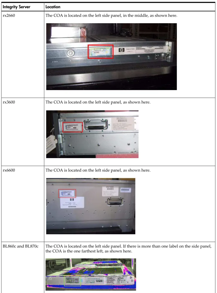
Table 1-2 Locating the Microsoft Certificate of Authenticity (COA) on your server Location
Integrity Server
The COA is located on the left side panel, in the middle, as shown here. rx2660
The COA is located on the left side panel, as shown here. rx3600
The COA is located on the left side panel, as shown here. rx6600
The COA is located on the left side panel. If there is more than one label on the side panel, the COA is the one farthest left, as shown here.
BL860c and BL870c
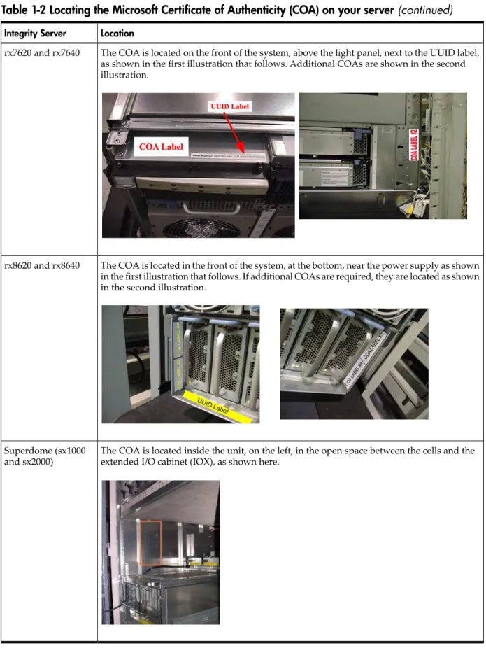
Table 1-2 Locating the Microsoft Certificate of Authenticity (COA) on your server(continued)
Location Integrity Server
The COA is located on the front of the system, above the light panel, next to the UUID label, as shown in the first illustration that follows. Additional COAs are shown in the second illustration.
rx7620 and rx7640
The COA is located in the front of the system, at the bottom, near the power supply as shown in the first illustration that follows. If additional COAs are required, they are located as shown in the second illustration.
rx8620 and rx8640
The COA is located inside the unit, on the left, in the open space between the cells and the extended I/O cabinet (IOX), as shown here.
Superdome (sx1000 and sx2000)
Task 6: Set up an Installation Method
You must choose one of the following methods to install the operating system: • Local installation methods:
— Headless console — GUI console
• Remote installation methods:
— Integrated Remote Console (IRC), available on rx2660, rx3600, rx6600, BL860c, BL870c, rx7640, rx8640, and Superdome/sx2000 servers only
— Preboot execution environment (PXE) + Windows Deployment Services (WDS), or PXE/WDS
If you are installing locally, you must set up your server with a headless or GUI console.
NOTE: For an overview of the benefits, concepts, and terminology of headless operating system installation on HP Integrity servers, see“Headless Windows Installations” (page 111).
Set up a Headless Console
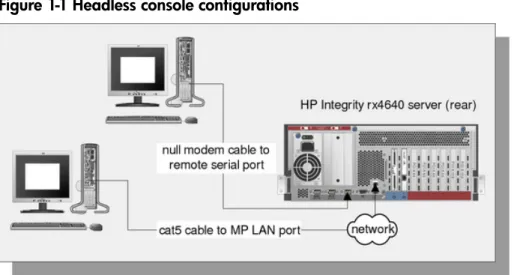
A headless console is a PC running terminal emulation software such as PuTTY (available from the web) or HyperTerminal, which connects to the server through its management processor (MP) serial port or LAN port. A headless console provides a method for connecting to servers that do not have legacy VGA graphics or PS/2 keyboard and mouse hardware. HP recommends that you configure servers this way (without legacy VGA or keyboard/mouse hardware) because they are easier to set up, maintain, and operate.
Figure 1-1shows headless consoles connected to an HP Integrity server.
Figure 1-1 Headless console configurations
When you use a headless console to install Windows, you can view detailed installation information for each component by monitoring the setup log channels. For more information about how to view this information, see the Windows Server 2003 and Windows Server 2008
Administration and User Guide.
From the headless console, you can access the EFI Shell, the management processor (MP), and the Microsoft Special Administration Console (SAC). You can use these utilities while installing and administering Windows Server 2008 on HP Integrity servers. For more information about the MP and SAC, see the Windows Server 2003 and Windows Server 2008 Administration and User
Guide.
You can configure a headless console in one of the following ways: • Using a null modem cable
• Using a cat5 LAN cable
• Using a Remote Serial Console (for rx2660, rx3600, rx6600, BL860c, BL870c, rx7640, rx8640, and Superdome sx/2000 servers only)
The first two methods require a terminal emulation application such as HyperTerminal or PuTTY. PuTTY is a free implementation of telnet and SSH for 32-bit Windows and UNIX. PuTTY provides an X terminal. You must use PuTTY version 0.59 or higher, available from the PuTTY website:
http://www.chiark.greenend.org.uk/~sgtatham/putty/download.html
Set up a Headless Console Using a Null Modem Cable
To set up the headless console using a null modem cable, complete the following steps: 1. Connect the PC to the server MP serial port with a null modem cable.
2. Install PuTTY on the client PC and specify these port settings: • Bits per second: 9600
• Data bits: 8 • Parity: none • Stop bits: 1
• Flow control: Xon/Xoff
3. Use the Keyboard Configuration Panel to map thebackspacekey toControl+H. 4. Boot the server.
5. Run PuTTY and pressEnter. The MP login prompt appears.
6. Enter your user name and password. The MP command prompt appears. 7. Enter theCOcommand to access the headless console.
8. The set up is complete. Proceed to the Headless Console installation process:“Install from a Headless Console” (page 29).
Set up a Headless Console Using a LAN
To set up the headless console over a LAN, complete the following steps: 1. Connect the PC to the server LAN port with a cat5 cable.
2. Use telnet to access the MP. The MP login prompt appears.
3. Enter your user name and password. The MP command prompt appears. 4. Enter theCOcommand to access the headless console.
5. The set up is complete. Proceed to the Headless Console installation process:“Install from a Headless Console” (page 29).
Set up a Headless Console Using a Remote Serial Console (rx2660, rx3600, rx6600, BL860c,
BL870c, rx7640, rx8640, and Superdome/sx2000 Servers Only)
To set up the headless console (on rx2660, rx3600, rx6600, BL860c, BL870c, rx7640, rx8640, and Superdome/sx2000 servers only) using Remote Serial Console, complete the following steps: 1. Using a secure web browser, enter the name or IP address of the server MP.
2. Enter your user name and password to log in to the System Management Homepage. 3. On the Remote Console tab, selectRemote Serial Consolein the left panel.
4. Click theLaunchbutton. A new window appears, providing access to the headless console. 5. The set up is complete. Proceed to the Headless Console installation process:“Install from
Set up a GUI Console
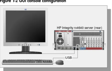
A GUI console is a VGA monitor, a USB HP keyboard, and a USB mouse connected to the server. (You can use a USB-to-PS2 converter to connect to a console switch.) If a VGA card is not installed, you must install the HP Graphics and USB Combo Card to use a GUI console. No other graphics card is supported by HP Integrity servers. Also, only HP keyboards are supported with this card.
Figure 1-2shows a GUI console connected to an HP Integrity server.
Figure 1-2 GUI console configuration
A GUI console provides complete access to all installation and administration tasks that you can perform on the server. You can use the GUI console to prepare the server for installation, install the OS, and verify server status after installation.
On servers configured with an internal graphics card, you can connect a monitor, keyboard, and mouse directly to the relevant ports. On servers without an internal graphics card, you must install an HP Graphics and USB Combo Card and connect the console to the relevant ports. Then, from an existing headless console, modify system configuration to redirect the output to the GUI console. The following table provides available graphics support.
Table 1-3 Graphics support on server models Graphics Card Server Model
Built-in video graphics rx2660, rx3600, rx6600, BL860c, BL870c
Optional HP Graphics and USB Combo Card (HP part number A6869B) rx7620, rx8620, Superdome/sx1000
Optional HP Graphics and USB Combo Card (HP part number A6869B) rx7640, rx8640, Superdome/sx2000
To install the HP Graphics and USB Combo Card using the Legacy interface (black background), complete the following steps:
1. Install the HP Graphics and USB Combo Card in an open PCI slot in the server. 2. Connect a VGA monitor, USB HP keyboard, and USB mouse to the relevant ports. 3. Boot the server to EFI.
4. At the headless console, from the EFI Boot Manager, selectBoot Option Maintenance Menu. 5. SelectSelect Active Console Output Devices.
6. Highlight the line with the graphics card PCI device.
If the line does not begin with an asterisk, the device is disabled. Use the space bar to change the state of the card from disabled to enabled (as indicated by the asterisk).
7. SelectSave Settings to NVRAMand thenExit. The video display is now directed to the GUI console.
8. The set up is complete. Proceed to the GUI Console installation process:“Install from a GUI Console” (page 37).
To install the HP Graphics and USB Combo Card using the Enhanced interface (gray background), complete the following steps:
1. Install the HP Graphics and USB Combo Card in an open PCI slot of the server. 2. Connect a VGA monitor, USB HP keyboard, and USB mouse to the relevant ports. 3. Boot the server to EFI.
4. From the EFI Boot Manager, selectBoot Configuration. 5. SelectConsole Configuration.
6. SelectSelect Output Console.
7. Select the graphics card PCI device and pressEnter. The video display is now directed to the GUI console.
8. The set up is complete. Proceed to the GUI Console installation process:“Install from a GUI Console” (page 37).
Set up an Integrated Remote Console (rx2660, rx3600, rx6600, BL860c, BL870c,
rx7640, rx8640, and Superdome/sx2000 Servers Only)
The Integrated Remote Console (IRC) lets you use Windows clients running Internet Explorer to remotely view and manage HP Integrity servers featuring the iLO 2 management processor. This functionality is supported on rx2660, rx3600, rx6600, BL860c, and BL870c servers only. It is also supported on rx7640, rx8640, and Superdome/sx2000 servers when the HP Lights Out Advanced KVM card is installed (part number: AD307A).
The IRC combines keyboard, video, and mouse into a remote, virtual interface. Use it to view the server display and interact with it. When you use IRC in combination with Virtual Media (See“Set up a Virtual Media (vMedia) Drive” (page 22)), you can perform remote GUI installations of server operating systems and software. You can also use the IRC to perform server maintenance tasks and run applications remotely that require keyboard and mouse input.
NOTE: You can use the IRC in place of the GUI Console method of installation anywhere the GUI method is described in this document.
The IRC and vMedia features are enabled only after you obtain and install an iLO 2 MP Advanced Pack license (part number AB500A). If you are not licensed and try to use these features, the message:iLO 2 feature not licensedappears. Free limited-term trial licenses are available.
For more information about the iLO 2 MP Advanced Pack licensing or to obtain a free limited-term license, go to:
http://h71028.www7.hp.com/enterprise/cache/279991-0-0-0-121.html.
For more information about iLO 2 functionality on HP rx7640, rx8640, and Superdome/sx2000 servers using the HP Lights Out Advanced KVM card, go to:
http://www.hp.com/products1/serverconnectivity/misc/ iLOADVKVMCard.html?jumpid=reg_R1002_USEN
Follow the factory installation or manual installation instructions located on the Integrated
Lights-Out Advanced Pack for HP Integrity Servers; Certificate of License to Use; License Installation Card to activate your license.
This document does not provide a complete description of IRC or vMedia. For more information about these powerful features, see the HP Integrity iLO 2 MP Operations Guide:
http://docs.hp.com/en/5991-6005/5991-6005.pdf
To set up an IRC (on rx2660, rx3600, rx6600, BL860c, BL870c, rx7640, rx8640, and Superdome/sx2000 servers only), complete the following steps:
2. Enter your user name and password to log in to the System Management Homepage. 3. On the Administration tab, selectLicensingin the left panel.
4. Enter the license number.
5. On the Remote Console tab, selectIntegrated Remote Consolein the left panel.
6. Click theLaunchbutton. IfLaunchis grayed out, the license might be invalid or expired. A new window appears, providing access to the IRC.
Set up a Virtual Media (vMedia) Drive
Virtual Media (vMedia) provides you with virtual devices that mimic physical hardware devices as if they were physically connected, such as a virtual CD/DVD drive that can connect through a network to the managed server. A vMedia device can be a physical CD/DVD drive on the management workstation, or it can be an image file stored on a local disk drive or network drive. Floppy disk or USB memory devices are not supported.
Booting from the iLO 2 MP CD/DVD enables you to upgrade the host system ROM, upgrade device drivers, deploy an OS from network drives, and perform disaster recovery of failed operating systems, among other tasks.
The iLO 2 MP device uses a client/server model to perform vMedia functions. The iLO 2 MP device streams vMedia data across a live network connection between the remote management console and the host server. The vMedia Java™ applet provides data to the iLO 2 MP as required.
NOTE: You can use a vMedia drive in place of a local CD or DVD drive anywhere that a local CD/DVD drive is described in this document.
To set up a vMedia drive (on rx2660, rx3600, rx6600, BL860c, BL870c, rx7640, rx8640, and Superdome/sx2000 servers only), complete the following steps:
1. Using a secure web browser, enter the name or IP address of the server MP.
2. Enter your user name and password to log in to the System Management Homepage. 3. On the Administration tab, selectLicensingin the left panel.
4. Enter the license number.
5. On the Virtual Devices tab, selectVirtual Mediain the left panel.
6. Click theLaunchbutton. If Launch is grayed out, the license might be invalid or expired. A new window appears, providing access to Virtual Media.
7. Complete one of the following actions:
• SelectLocal Media Drive, specify the CD or DVD drive on your client machine, and insert the CD or DVD into that drive.
• SelectLocal Image Fileand specify the ISO image of the CD or DVD.
8. ClickConnect. The server now detects a new USB drive attached to it. This is the vMedia drive.
Set up PXE/WDS
A Windows Deployment Services server (WDS) is a specialized Windows server used to perform multiple software installations across a network. The WDS server, working with a Preboot Execution Environment agent (the PXE client) residing on target systems, performs automated installations. This method of installation offers the following advantages:
• Installations are automated. No user intervention is needed. • You can install multiple servers in one batch job.
• Each server receives a standardized image.
• You can perform an installation from anywhere on the intranet.
Figure 1-3shows a sample PXE/WDS setup.
Figure 1-3 PXE/WDS configuration
NOTE: When you perform a PXE/WDS headless installation, note the following:
• Headless installations using PXE/WDS are not supported with Windows Server 2008. Use the HP Reinstallation media instead.
• Do not connect the WDS server to the Integrity server using your intranet during initial Windows OS installation. Set up a small private network, populated with the WDS server, a hub, and the system LAN NIC of the HP Integrity server. This protects the intranet from errors that might occur during the Windows installation. When the Windows OS installation has completed, connect the WDS to the target Integrity servers using your intranet.
WDS enables you to create, maintain, and quickly install identical OS and software configurations on multiple headless systems with a predefined level of user interaction. WDS uses the PXE to enable client computers without an operating system to boot remotely to a WDS server. The WDS server then installs the OS over a TCP/IP network connection.
You can create different sets of WDS images for different groups of client computers. You can also use Group Policy settings to limit the installation options that WDS presents to clients. In addition, you can configure WDS for interactive or automated installations.
Set up a WDS Server
Setting up WDS servers on your network requires careful planning, design, and implementation. The following checklist provides an overview of the tasks involved in setting up a WDS server: • Ensure that your WDS server and client (Integrity server) hardware meet the WDS hardware requirements. The server hardware must meet the minimum requirements for the version of Windows Server 2008 that you are installing.
• Ensure that your network is based on TCP/IP, and that a Domain Name System (DNS) server exists on the network. You do not need to use the Microsoft version of DNS.
• Ensure that a Dynamic Host Configuration Protocol (DHCP) server exists on the network. You do not need to use the Microsoft version of DHCP.
• Ensure that Active Directory exists on the network. • Install the WDS component on the WDS server. • Run the WDS Setup Wizard.
For detailed descriptions of the concepts, tasks, best practices, and troubleshooting tips for setting up a WDS server, see the Microsoft Windows Server 2008 Technical Reference website:
http://www.microsoft.com/windowsserver2008/en/us/product-documentation.aspx
Specifically, go to this link:
http://technet2.microsoft.com/windowsserver2008/en/library/ fbd2d37b-4127-43fd-a079-f78bbd44b7601033.mspx?mfr=true
Install WDS
You can install WDS using the Control Panel or an unattended Setup answer file. To install using Add or Remove Programs, complete the following steps:
1. Go toStart > Settings > Control Panel, double-clickAdd or Remove Programs, and then selectAdd/Remove Windows Componentsto install the WDS component.
2. Open the WDS Setup Wizard and clickNext. The WDS Setup wizard prompts you for information about specific settings used in the WDS installation. The wizard prompts you to do the following:
a. Enter the disk drive and directory to install WDS. The disk must be dedicated to the WDS server with a recommended minimum 4 GB of space.
b. Select Respond to client computer requesting service. The WDS server begins responding to client computers when the wizard is complete. If you want the WDS server to respond only to prestaged client computers in Active Directory, select Do not
respond to unknown client computers.
c. Enter the location of the client images. This can be the Windows Server 2008 CD or a shared folder on the network that contains the installation files.
d. Enter help text that describes the OS installation choices to users or clients of WDS.
Configure WDS
After the WDS Setup Wizard completes, depending on the settings chosen, the WDS server services client computers or pauses while you configure advanced settings using WDS administration settings. The following configuration options are available:
• Specify which WDS servers are allowed to run on your network. This option prevents the use of unauthorized (often referred to as rogue) WDS servers, ensuring that only WDS servers authorized by administrators can service clients. If an attempt is made to start an unauthorized WDS server on the network, it is shut down and cannot service client computers. A WDS server must be authorized before it can service client computers. • Use the Active Directory Users and Computers snap-in to set properties on WDS servers
that control how the server supplies WDS to requesting clients. To access the snap-in go to
Start > Programs > Administrative Tools, and then clickActive Directory Users and Computers.
• Use Group Policy to specify which installation options are presented to groups by the Client Installation wizard (CIW). For example, you can choose to allow a group access only to the automatic setup option, and restrict access to all other options to administrators.
• Use security descriptors or discretionary access control lists (ACLs) to specify which users or groups can access the OS images available on the WDS server. You can use this method to guide users through the selection of the unattended OS installation relevant for their account privileges. By default, when an OS image is added to a WDS server, the image is available to all users serviced by that WDS server.
To configure settings for new clients for WDS, complete the following steps: 1. Open Active Directory Users and Computers.
2. In the console tree, go toActive Directory Users and Computers > Applicable domain > Applicable organizational unit(such as Computers/Applicable WDS server), and right-click the applicable WDS server.
3. ClickProperties. Then, in the Properties dialog box, go to the Remote Install tab and click
Advanced Settings.
4. In the Advanced Settings dialog box, go to the New Clients tab.
5. Select the client computer naming format you want to use, or clickCustomizeto create a client computer naming format.
6. To specify where to create the client computer account, click one of the following options: • Default directory service location
• Same location as the user setting up the client computer • The following directory service location
7. If you choose the last option inStep 6, clickBrowseand specify where to create the computer accounts.
Authorize a WDS Server in Active Directory
A WDS server must be authorized in Active Directory to respond to clients requesting service. If WDS is installed on a server that is not an authorized DHCP server, or is added to a DHCP server that is not authorized in Active Directory, complete the following steps:
1. Log in to the domain in which the WDS server resides. The account you use must be a member of the Enterprise Admins group.
2. From the Start menu, point to Programs and Administrative Tools, and clickDHCPfrom the list. This starts the DHCP Management snap-in.
3. Right-click the DHCP root node in the scope pane, and then clickManage Authorized Servers.
4. ClickAuthorize, enter the IP address or name of the WDS server, and then clickOK. When prompted to ensure that this is the correct WDS server to authorize, clickYes.
The server will not respond to client requests until the changes to Active Directory take effect. For these rights to apply immediately, on the domain controller where your rights have been set, complete the following steps:
1. On the Start menu, clickRun. 2. Enter thecmdcommand.
3. At the command prompt, enter:
secedit /refreshpolicy /MACHINE_POLICY
Use the Client Installation Wizard
The following installation options are included in the Client Installation Wizard (CIW). Automatic setup is available by default. WDS uses Group Policy settings that allow access to the automatic setup option only, which restricts administrators from the other installation options in the following list:
• Automatic Setup—This option enables you to select which OS to install but it does not prompt you for specific configuration settings. If only one operating system option is offered, you are not prompted, and an unattended installation of the OS image starts.
• Custom Setup—This option enables you to override the automatic computer naming process and the default location in Active Directory where client computer accounts will be created. Help desk or administrators can use this option to preinstall a client computer for someone within the enterprise.
• Restart a Previous Setup Attempt—This option restarts the OS installation process when an installation attempt fails before completion. This option does not copy files from where the
previous installation attempt failed; however, you are not required to answer questions answered in the CIW from the previous setup attempt.
• Maintenance and Troubleshooting—This option provides access to third-party maintenance and troubleshooting tools that you can use before installing the OS. Examples of these tools include system flash BIOS updates, computer diagnostic tools, and virus scanning utilities.
Task 7: Prepare the Server Hardware for OS Installation
NOTE: If you are installing Windows Server 2008 on a server currently running Windows Server 2003, you must first upgrade the system firmware to the latest version. You can download the latest system firmware from:http://www.hp.com
Complete the following tasks to set up the server hardware for OS installation.
Set Up the Boot Drive
The OS installs through the boot controller detected as adapter zero to the drive detected as drive zero.
CAUTION: HP strongly recommends that only the target OS drive be connected during installation. This ensures that the OS is installed on the correct drive. Make sure that the Z: drive is free. Windows Server 2008 creates the EFI partition here.
To set up the boot drive, complete the following steps: 1. Power off the server.
2. Make a note listing all device connections so you can reconnect them after the installation. 3. Disconnect mass storage devices from all controllers except the boot controller.
4. Configure the boot controller and boot drive. HP recommends that you install the boot controller in the root cell.
NOTE: If you are using an HP Smart Array controller, see the controller user guide for more information. You can interrupt the boot process to invoke the EFI-Based Option ROM Configuration for Arrays (ORCA). To invoke this utility:
1. PressF8on the GUI console.
2. PressESC 8on the headless console.
Boot to EFI
To launch the EFI Shell, complete the following steps:
1. Boot the server. The server automatically goes to the EFI Boot Manager Menu. 2. Scroll down and selectEFI Shell.
3. PressEnter.
4. Choose from the following:
• If you are using the Enhanced EFI Boot Manager Menu (gray background), selectEFI Boot Manager Menu > EFI Shell.
• If you are using the Legacy EFI Boot Manager Menu (black background), selectEFI Boot Manager Menu > EFI Shell [Built-in].
Locate the DVD/CD Drive
When hardware (for example, HDD, a USB device, vMedia, or a DVD-ROM drive) is added to a system after it has booted to EFI, the EFI Shell environment does not detect the new device. You must reconnect the device driver for the EFI Shell to recognize the device.
The EFI Shell environment creates default mappings for device handles that support a recognized file system. After you change the system configuration or add a new device, you must regenerate these mappings.
To enable the EFI Shell to detect and access the DVD/CD drive, complete the following steps: 1. From the EFI Shell, enter thereconnect –rcommand.
Thereconnectcommand reconnects drivers from a device, disconnecting drivers from all devices and then reconnecting them. If you do not specify a device handle, the reconnect operation is performed on all handles in the system. If you specify a device handle, only the device handle and the devices below it are reconnected.
2. From the EFI Shell, enter themap -rcommand.
The-roption regenerates all mappings in a system. The EFI Shell displays the device mapping table, as follows.
fs0 : Acpi(PNP0A03,0)/Pci(2|0)/Ata(Primary,Master)/CDROM(Entry1) blk0 : Acpi(PNP0A03,1)/Pci(1|0)/Scsi(Pun0,Lun0)
blk1 : Acpi(PNP0A03,0)/Pci(2|0)/Ata(Primary,Master)
blk2 : Acpi(PNP0A03,0)/Pci(2|0)/Ata(Primary,Master)/CDROM(Entry1)
3. Note the device name of the CD device (in the above example):
fs0
You use this to explore the contents of the CD or DVD.
Themapcommand displays or defines a mapping between a user-defined name and a device handle. The most common use of this command is to assign drive letters to device handles that support a file system protocol. When these mappings are created, the drive letters can be used with all file manipulation commands.
Use themapcommand to create or to delete mappings with the-doption. If you use the
mapcommand without parameters, all current mappings are listed. If you use the-voption,
the mappings are shown with additional information on each mapped handle. The following table describes the device mapping fields.
Table 1-4 EFI device mapping fields Description
Item
This is a block device that indicates a physical drive or a partition on a physical drive. A physical drive can be a hard disk drive or a removable media drive. A
Partn
appears when a disk drive contains a partition.
blkn
Acpiis Advanced Configuration and Power Interface. The device type is the first entry in parentheses. The second entry,X, is the PCI host number.
Acpi(Device,X)
This indicates PCI-related information.Dis the PCI device/slot number andFis the PCI function number.
Pci(D/F)
This denotes the physical characteristic of the SCSI disk.Punis the SCSI number andLun
is the LUN number on the physical device.
Scsi(Pun.Lun)
This indicates the partitionPartand EFI signatureSigon the partition.
HD(Part,Sig)
Set ACPI Flag to Windows (Cell-Based Servers Only)
On cell-based servers, you must set the Advanced Configuration and Power Interface (ACPI) flag to the value relevant for the OS it boots. For the server to boot to Windows Server 2008, set the ACPI flag towindows.
If you purchased your server with a Windows OS option, this flag is set towindowsin the factory. If you purchased the server with a different OS or no OS, you must set this flag towindows.
CAUTION: If you boot the server to Windows Server 2008 without setting the ACPI flag to
windows, the OS displays a blue screen error. To set the ACPI flag, complete the following steps:
1. From the EFI Shell, enter theacpiconfigcommand.
EFI displays the current ACPI settings. If the flag is set towindows, EFI displays
acpiconfig: windows.
2. If the flag is not set towindows, enter theacpiconfig windowscommand.
3. Enter theacpiconfigcommand again to display the settings again and verify that the flag is set correctly.
NOTE: Updating the system firmware can reset this flag todefault. Verify that the flag is set towindowsafter you flash the system firmware.
Set Cell Local Memory to 100% (Cell-Based Servers Only)
HP recommends that you set the cell local memory (CLM) parameter to 100% for optimal server performance. This setting allocates all available cell local memory for the use of that cell only, preventing unnecessary reads and writes to physical memory over the server backplane. Modify CLM settings for each nPartition using the nPartition command (parmodify). You must first install nPartition tools on the Integrity server or on a remote management station. For information on installing these tools, see the nPartition Guide at:
http://docs.hp.com/en/windows.html
To set the CLM parameter, complete the following steps:
1. From the server console, run theparmodifycommand with-p#and-m#options to modify
each cell’s attributes in each nPar you modify. For example:
parmodify -p0 m0::::100%
where-pis the partition number and-mis the cell number in that partition. Sets cell local memory to 100% in cell 0, partition 0.
2. Restart the server for the changes to take effect.
Specify the Network Interface Card for a Network Boot
PXE is built on common Internet protocols and services, including TCP/IP, DHCP, and TFTP. PXE extensions to DHCP enable WDS servers to communicate with the network-bootable HP Integrity servers.
You can specify the network interface card (NIC) for PXE to use to communicate with the WDS server. When the HP Integrity server boots from this NIC, it effectively boots from the remote WDS server. Working with the WDS server, PXE installs a new image of the Windows Server 2008 on the HP Integrity server.
To enable PXE on the HP Integrity server from the EFI Shell, complete the following steps: 1. From the EFI Boot Manager, selectEFI Shell. The device mapping table appears. 2. Enter thelanboot selectcommand.
3. At theSelect desired LAN:prompt, enter the number of the NIC connected to the PXE server.
4. Exit the EFI Shell.
2 Installing the OS
This chapter provides instructions for installing the operating system (OS) using a headless console, a GUI console, or a Preboot Execution Environment (PXE) enabled network interface card (NIC). This chapter also provides reinstallation instructions for Windows Server 2008. Each method comprises a series of tasks, concluding with two tasks that verify that the OS was installed correctly. You must install the HP Integrity Support Pack after installing the OS. You must also install operating system and security updates using the Smart Update media.
If the Windows Server 2008 operating system is installed on your system, or if it was installed by HP before your system was delivered, you do not need to perform the steps in this chapter. Proceed toChapter 3 “Installing and Configuring the Management Tools”and begin the installation of your management tools software.
If your Windows Server 2008 OS is not installed, if you want to reinstall it, or if you want to migrate to Windows Server 2008 from another OS, install the OS and OS updates using the steps described in this chapter, in the following order:
• If you are installing your OS for the first time, or migrating from a different operating system: — If you are installing locally, choose one of the following options:
◦ “Install from a Headless Console” (page 29)
◦ “Install from a GUI Console” (page 37)
— If you are not installing locally, choose one of the following options: ◦ “Install from PXE” (page 45)
◦ “Using Integrated Remote Console to Install Windows on rx2660, rx3600, rx6600, BL860c, BL870c, rx7640, rx8640, and Superdome/sx2000 Servers” (page 56)
• If you are reinstalling your OS, choose one of the following options: — “Reinstall from a Headless Console” (page 46)
— “Reinstall from a GUI Console” (page 48)
• After installing or reinstalling your OS, perform the following tasks: — “Activate the OS” (page 50)
— “Apply OS Updates Using the Smart Update Media” (page 53)
— “Enable Windows Components” (page 54)
— “Verify System Device Drivers and Register for Updates” (page 55)
— See if you need to perform any final tasks here:“Miscellaneous Installation Issues” (page 56)
Install from a Headless Console
This section describes how to install the OS using a Headless console and the EFI-Based Setup Utility (EBSU). EBSU provides an easy-to-use interface to flash the firmware, partition the hard disk, install diagnostic tools, configure storage controllers, and run other EFI utilities. For an overview of the benefits, concepts, and terminology of headless OS installation on HP Integrity servers, see“Headless Windows Installations” (page 111). For this procedure, you should be connected to the management processor (MP) of the target server using a terminal emulation application such as HyperTerminal.
To run EBSU, complete the following steps: 1. Power on the server. The server boots to EFI.
You can use the EFI Boot Manager from the Enhanced interface (gray background) or the Legacy interface (black background).
3. From the EFI Boot Manager Boot Menu, selectInternal Bootable DVDand pressEnter. EBSU starts and displays the Welcome screen.
4. ClickOKand pressEnter.
5. From the Main Menu, selectExpress Setupand pressEnter.
Figure 2-1 EBSU Main menu
6. EBSU displays a screen with special instructions for RAID users. Follow those instructions if applicable, then pressEnterto continue.
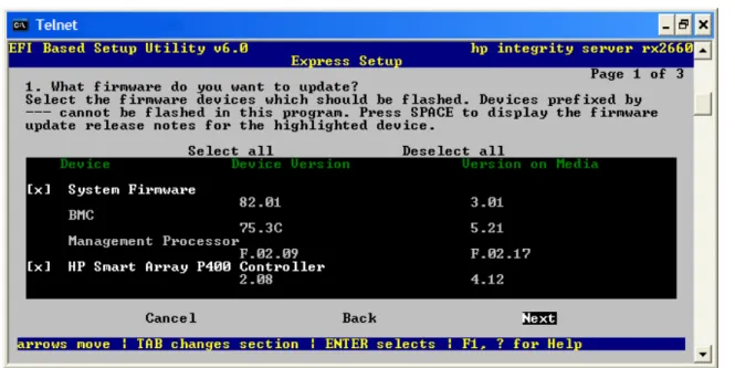
7. EBSU displays the firmware update screen, listing each device, its installed firmware version, and the firmware version on the Smart Setup media. Select the firmware devices you want to update. To continue, selectNextand pressEnter.
Figure 2-2 EBSU Firmware Update screen
NOTE: You might not be able to use EBSU to flash the firmware of some devices. You cannot flash the firmware if the installed version is the same or higher than the version on the Smart Setup media. Also, you cannot use EBSU to flash the Management Processor (MP) firmware. You must download the latest MP firmware from the HP Integrity support site and flash it separately. See:http://www.hp.com/support/itaniumservers/.
8. EBSU displays the partition disk screen. SelectESP + HPSP + MSRorESP Only. HP recommends the default — ESP + HPSP + MSR — as a way to simplify the maintenance of your server.
Figure 2-3 EBSU Partition Disk screen
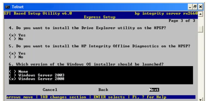
9. EBSU displays an install options screen. Accept the default options to install the Drive Explorer utility (for browsing a drive in EFI) and offline diagnostic tools (from the HP Integrity Offline Diagnostics CD) in the HPSP partition. Also specify which version of the Windows OS Installer to launch (in this case:Windows Server 2008). Then selectNextand pressEnter.
10. When prompted by EBSU, enter the Product Key and Administrator password.
Figure 2-5 EBSU Product Key screen
11. EBSU displays a warning that all partitions on the disk will be overwritten. SelectContinue
and pressEnter.
12. EBSU displays a warning that a temporary MSDATA partition will be created. PressEnter. 13. EBSU displays an informational pop-up that the installation will begin. PressEnter. 14. The installation begins and progresses through partition creation and firmware updates.
Insert the HP Integrity Offline Diagnostics CD when prompted, then pressEnter.
NOTE: At this point, if you cannot locate the Offline Diagnostics CD, selectSkipand press
Enterto bypass installation of the diagnostic utilities.
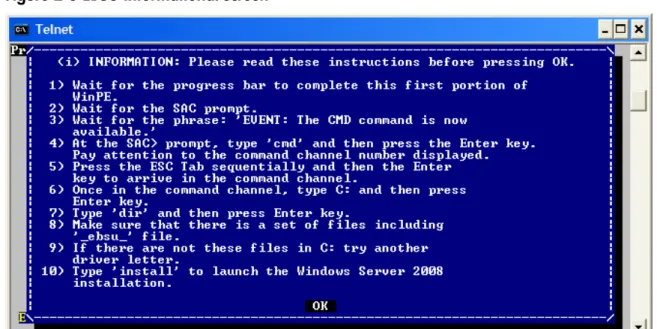
15. EBSU displays an informational screen. Write down the instructions in case you need them later (for example, if the system cannot locate the Internal Bootable DVD drive), and press
Enter.
Figure 2-6 EBSU Informational screen
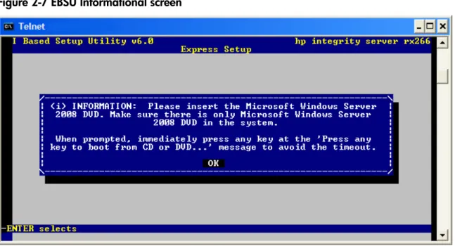
16. When EBSU prompts you, insert the Microsoft Windows Server 2008 operating system CD and pressEnter.
NOTE: If you are installing an HPVM Windows guest, you must issue anINcommand (for “insert”) from the HPVM console menu every time you insert a disc. If you do not issue the command, the server does not recognize the disc and appears to hang.
Figure 2-7 EBSU Informational screen
17. Press any key when prompted to continue (be ready to do this quickly or the system could time out). The Windows Boot Manager screen displays. PressEnterto selectWindows Setup [EMS Enabled].
Figure 2-8 Windows Boot Manager screen
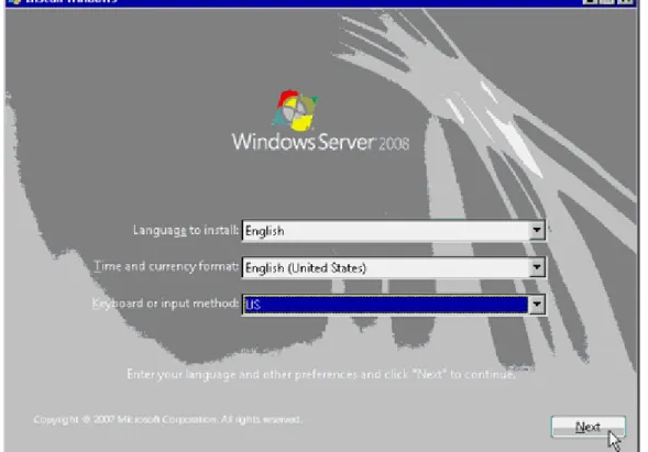
18. Windows begins loading files from the disk. When the progress bar reaches 100 percent, the Install Windows screen appears. Select your default language, time and currency formats, and keyboard or input method, and then clickNext.
Figure 2-9 Install Windows screen
19. In the next screen, clickInstall Now.
20. In the next screen, enter your Product Key again and clickNext.
21. In the License Terms screen, check the box labeledI accept the license termsand click
Next.
22. In the next screen, clickCustom (advanced).
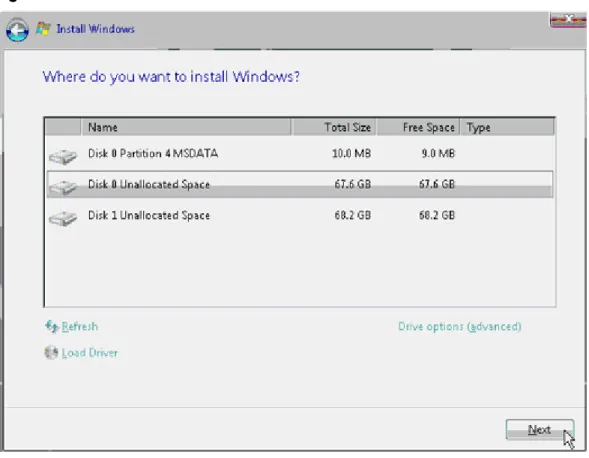
23. In the next screen you are asked on which system partition to install the operating system. If more than one partition is available, you should select one that is marked “Unallocated” and also one that is formatted as NTFS. Then clickNext.
Figure 2-10 Install Windows screen
24. In the next pop-up screen, clickNextto continue. Installation of the operating system begins. 25. When the installation finishes, you are prompted to change your password to log on the
first time. ClickOK.
26. Enter the new system administrator password two times and click the arrow button. 27. The password change is confirmed. ClickOKto continue.
28. The system finishes booting to the Desktop for the first time and launches the Initial Configuration Tasks screen.
Figure 2-11 Initial Configuration Tasks screen
29. At this screen you can set up and configure system-wide settings and perform tasks such as:
• Set time zone
• Configure networking
• Provide computer name and domain info • Enable automatic updating and feedback • Download and install updates
• Add roles • Add features
• Enable Remote Desktop • Configure Windows Firewall
You should configure some of these settings now to prepare your system for its intended use in your production environment. However, it is beyond the scope of this document to make specific recommendations, since each user has a unique combination of factors such as system I/O, storage, intended use, and so on. See your System Administrator and the operating system online help.
30. Simple Network Management Protocol (SNMP) is required by the system management tools described later in this document (HP Insight Management Agents and System Management Homepage). These tools use SNMP to monitor network devices for conditions that require administrative attention. To install SNMP, complete the following steps:
a. In the Initial Configuration Tasks screen, clickAdd Features.
b. In the Select Features screen, put a check mark in the box next toSNMP Servicesand clickNext.
c. In the Confirm Selection screen, clickInstall.
d. When the installation finishes, clickCloseto exit back to the Initial Configuration Tasks screen. Then clickCloseagain.
e. Restart the system.
NOTE: Another way to install SNMP is from the command prompt, by entering:
ServerManagerCmd.exe -install SNMP-Service, and then restarting the system. With this method you must still configure the service, as described in the next step.
31. After the system restarts, configure SNMP by completing the following steps: a. From the Windows Desktop, selectStart > Administrative Tools > Services. b. In the Services window, right-clickSNMP Serviceand clickProperties. c. In the Properties window, click on the Security tab.
d. In the Security tab, clickAddto add a Community string. Name the string and assign it access rights depending on your system requirements.
e. ClickApply, and then clickOKtwice to apply the change. f. Exit the Services window.
32. Installation of the OS is complete.
After installing the operating system, perform these tasks next: • “Install the Integrity Support Pack (ISP)” (page 61)
• “Activate the OS” (page 50)
• “Apply OS Updates Using the Smart Update Media” (page 53)
• “Enable Windows Components” (page 54)
• “Verify System Device Drivers and Register for Updates” (page 55)
• See if you need to perform any additional tasks described here:“Miscellaneous Installation Issues” (page 56)
Then go to the sections describing configuration of the management tools, and perform these tasks:
• “Configure System Management Homepage” (page 64)
• “Configure the Management Agents” (page 66)
• “Verify Installation of the nPartition Management Tools” (page 72)
Install from a GUI Console
This section describes how to install the OS using a GUI console and the EFI-Based Setup Utility (EBSU). EBSU provides an easy-to-use interface to flash the firmware, partition the hard disk, install diagnostic tools, configure storage controllers, and run other EFI utilities.
To run EBSU, complete the following steps: 1. Power on the server. The server boots to EFI.
You can use the EFI Boot Manager from the Enhanced interface (gray background) or the Legacy interface (black background).
2. Load the HP Smart Setup media into the server DVD drive.
3. From the EFI Boot Manager Boot Menu, selectInternal Bootable DVDand pressEnter. EBSU starts and displays the Welcome screen.
4. ClickOKand pressEnter.
Figure 2-12 EBSU Main menu
6. EBSU displays a screen with special instructions for RAID users. Follow those instructions if applicable, then pressEnterto continue.
7. EBSU displays the firmware update screen, listing each device, its installed firmware version, and the firmware version on the Smart Setup media. Select the firmware devices you want to update. To continue, selectNextand pressEnter.
Figure 2-13 EBSU Firmware Update screen
NOTE: You might not be able to use EBSU to flash the firmware of some devices. You cannot flash the firmware if the installed version is the same or higher than the version on the Smart Setup media. Also, you cannot use EBSU to flash the Management Processor (MP) firmware. You must download the latest MP firmware from the HP Integrity support site and flash it separately. See:http://www.hp.com/support/itaniumservers/.
8. EBSU displays the partition disk screen. SelectESP + HPSP + MSRorESP Only. HP recommends the default — ESP + HPSP + MSR — as a way to simplify the maintenance of your server.
Figure 2-14 EBSU Partition Disk screen
9. EBSU displays an install options screen. Accept the default options to install the Drive Explorer utility (for browsing a drive in EFI) and offline diagnostic tools (from the HP Integrity Offline Diagnostics CD) in the HPSP partition. Also specify which version of the Windows OS Installer to launch (in this case:Windows Server 2008). Then selectNextand pressEnter.
Figure 2-15 EBSU Install Options screen