Web Based Fault Detection System
K.Harshini, M.Tech Embedded System Arvind Vishnubatla. Professor,GRIET, Hyderabad
ABSTRACT
Embedded systems became an important part of our life. Addressing functional safety is a major challenge with increasing complexity. Typical examples of safety-critical embedded systems include vehicle safety or driver assistance systems with accident prevention. This specification applies to a system allowing to remotely monitoring appearance of faults on a device network so that to localize faulty sections and send patrols for reconfiguration of the network accordingly. The system shall be made of Fault detection systems with wireless communication to be installed on the networks, as specified in this document. A piece of software in the control centre is used to display the fault information from these Fault passage indicators. This shall be referred to as Fault Monitoring software. The Control Centre shall continuously measure the parameters of the devices connected wirelessly over the network. A suitable wireless interface shall facilitate acquiring this information to allow reading it remotely at the control centre.
Keywords—CC3000TivaCTm4C123gh6pm, JTAG, USB, Fault Monitoring System reed Muller encoder and decoder.
1. INTRODUCTION
Embedded Systems are becoming ubiquitous and an integral part of our everyday life. Addressing functional safety is a major challenge with increasing complexity. Typical examples of safety-critical embedded systems include vehicle safety or driver assistance systems with accident prevention. However, functional safety is becoming more prevalent not just in the automotive sector, but also in industrial markets such as aviation, solar energy, and the medical sector. Memory devices increasingly provide built-in error correction in order to restore corrupted data and also to maximize the number of writes in flash memory .
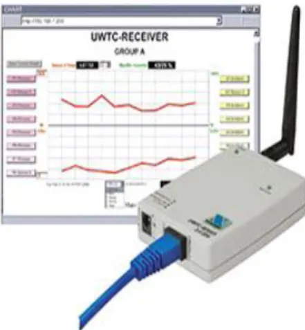
Fig 1.1 Web based fault Monitoring
1.1 Aim of the project
The Main objective of this project is transmitting the data wirelessly from control centre to the remote device and monitor the faults generated during transmission, and also provide security for the transmitted data.
A typical software design consists of
1. Identification of components and candidates 2. Generation of Product design alternatives 3. Transition Plan selection
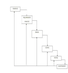
Fig 1.2 Software life cycles
The software design is decomposed in to the following steps
1. Define the network by identifying the processing nodes, gates and links.
2. Define the software objects
3. How they might interact with one another 4. Map the software objects on to the processing
nodes
5. Define an experiment to stimulate the model during simulation and to collect pertinent dates for functional and belovinal analysis.
The design for fault detection is implemented on a cc3200 simple link wi-fi. The design strategy adopted for testing in illustrated in the state machine as shown in the below figure
It is desirable to implement the protocols according to the flow diagram as shown below. The message protocol for the project is given below here the message is sent in the form of packets
The control centre will communicate with the remote device for communicating the message there are many layers included in between these layers are shown in the below figure
Fig 1.4 Layer to layer transmission of data between control center and remote device
1.2 Requirements analysis
a) Scope
This specification applies to a system allowing to remotely monitoring appearance of faults on an device network so as to localize faulty sections and send patrols for reconfiguration of the network accordingly.
b) Measurements
Any change of state of information shall generate a time-stamped event stored in the Control Centre interface memory. The event storage capacity shall be at least 100 events.
d) Wi-Fi
Simple Link CC3200 device is a wireless MCU that integrates a high-performance ARM Cortex-M4 MCU, allowing customers to develop an entire application with a single IC. With on-chip Wi-Fi, Internet, and robust security protocols, no prior Wi-Fi experience is required for faster development.
e) Error Detection and Correction
A suitable error detection algorithm is developed. The design for fault detection is implemented on two CC3200 simple link wifi kits
The design strategy adopted for testing is illustrated in the Figure 1.4.
Fig 1.5 Control centre state machine
Message Sequence Chart
Control centre remote device
Fig1.6 Message Sequence Chart
Message Types
01 Send Device Status 02 Reset Device 03 Shutoff Device 04 Sound Safety
2. CC3200-SIMPLE LINK WI-FI
Created for the Internet of Things (IoT), the Simple Link CC3200 device is a wireless MCU that integrates a high-performance ARM Cortex-M4 MCU, allowing customers to develop an entire application with a single IC. With on-chip Wi-Fi, Internet, and robust security protocols, no prior Wi-Fi experience is required for faster development.
Applications
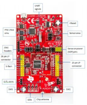
Fig 2.1CC3200 Launch Pad Overview
2.1 Architecture Overview
The building blocks of CC3200 system-on-chip are shown in FIG 2.1
Fig 2.2 CC3200 MCU+WIFI SYSTEM ON CHIP
2.2 Processor Core
exceptional system response to interrupts at low power consumption while optimizing memory footprint - making it an ideal fit for embedded applications.
Key features of ARM Cortex-M4 processor core are: Thumb-2 mixed 16- and 32-bit instruction set
delivers the high performance expected of a 32-bit ARM core in a compact memory size – enabling richer applications within a given device memory size.
Single-cycle multiply instruction and hardware divide • Atomic bit manipulate on (bit-banding), delivering maximum memory use and streamlined peripheral control
2.3 Cortex-M4 Processor a) Overview
CC3200 incorporates a dedicated instance of ARM® Cortex-M4 CPU core for executing application code with or without RTOS. This processor core is not used in any manner for running any networking or device management task.
Features include:
32-bit ARM® Cortex™-M4 architecture optimized for small-footprint embedded applications
80-MHz operation Fast interrupt handling
b) System-Level Interface.
Register can be accessed in either privileged or unprivileged mode.
3. DESIGN
The Wi-Fi network processor subsystem features a Wi-Fi internet on a chip and contains an additional dedicated ARM MCU that complete offloads the applications MCU. This application aims to exhibit the cc3200 device as a station in a simple network
Source files briefly explained
Main.c- main file creates the simple link task which does most of the network related operations, a wlan station made task makes calls to the network related APIs of simple link library.
Gpio_if.c- gpio interface files for LED APIs Main.c flowchart
Fig 3.1 main.c
Flow chart for uart
(a)
(b)
4. CODE COMPOSER STUDIO
Introduction
CC3200 can be programmed in different IDE’S like cc studio, IAR, energies etc.The type of IDE we are using here is code composer studio v 6.0.
CCS 6.0 or higher is required. When CCS has been launched, and a workspace directory chosen, use Project→Import Existing CCS Eclipse Project. Direct it to the desired demo’s project directory containing main.c.
5. Testing and results
Software testing
The purpose of software testing is to uncover bugs for emoval and ensure the synthesis compliance with the requirements.
Fig 5.1 Software testing steps
Here we follow the strategy of incremental testing where the software is tested piece by piece. First each software module unit to be tested, and then the tested modules are integrated in to the larger subsystem for integration testing finally the entire software system is built for system testing.
CONCLUSION
The project uses two CC3200, this is self contained MCU and Wi-Fi module here this CC3200 has ARM cortex M4 processor. This is a very advanced processor in which the numbers of instruction cycles are reduced and data transmission is also very fast when compared to other ARM processors.CC3200 wifi module is used to transfer data wirelessly between control centre and the remote device.
Future scope
A sensor and a LCD display can be used in this system.
Different types of booster packs are available for cc3200 like audio, video, sensors etc.. by using this module we can implement many applications.
We can also implement this type of system in automobiles by using CAN. So that the devices communicate internally and if any fault is generated we can use the fault monitoring software to rectify the fault wirelessly.
REFERENCES
[1] B. Le Floch , M. Alard and C. Berrou "reed Muller code", Proceedings of the IEEE, vol. 83, no. 6, pp.982 -996 1995.
[2] CC3200 Microcontroller Data Sheet.
[3] Tiva C Series TM4C123x Microcontrollers Silicon Revisions 6 and 7 Errata.