DC Link Capacitor Voltage of D-Statcom With Fuzzy Logic
Supervision
M.Pavani, Dr.I.Venugopal,
II M.Tech (Pe&Ps), Professor, Kecw,Kesanupalli, Narsaraopet
E-Mail:[email protected]
Abstract:
In a DSTATCOM, generally, the dc capacitor voltage is regulated using a PI controller when various control algorithms are used for load compensation. However, during load changes, there is considerable variation in dc capacitor voltage which might affect compensation. In this work, a fuzzy logic based supervisory method is proposed to improve transient performance of the dc link. The fuzzy logic based supervisor varies the proportional and integral gains of the PI controller during the transient period immediately after a load change. An improvement in the performance of the controller is obtained because of appropriate variation of PI gains using expert Knowledge of system behaviour and higher sampling during the transient period. A 50% reduction in the error in dc link capacitor voltage during load change compared to a normal PI-controller is obtained. The voltage waveform also has a faster settling time. The efficacy of the proposed strategy is proved using detailed simulation studies.
Keywords: DC link voltage control, DSTATCOM, Fuzzy supervisor, Instantaneous symmetrical components, PI-controller, power quality, transient response, voltage source inverter.
1. INTRODUCTION:
Increased use of non-linear loads and the proliferation of power electronic based equipment have led to many problems in the power distribution network. Solid state switching devices such as thyristors and other switches are used in Uninterruptible Power Supplies (UPSs), variable speed drives etc. Because of their inherent non-linearity, they draw reactive power and harmonic current components from the utility. This could lead to low system efficiency and poor power factor, apart from harmonic pollution of the system. Many power quality problems usually occur in the
distribution system. Harmonics and non-linear loads from a single customer can affect the quality of power received by other customers. Low power factor loads can cause power losses at the distribution feeder. The utility does not have any control over the loads. The conventional approach to this solution has been the use of passive power filters. Though they are a low-cost solution, there are disadvantages to using them, the main risk being that of resonance with the system impedance. They are also bulky and overcompensation can lead to a lower power factor. Active power filters can overcome these problems. The Distribution Static Compensator or the DSTATCOM is a shunt connected active power filter or custom power device which injects current at the point of common coupling PCC). The main aims of the DSTATCOM are:
a) To cancel the effect of harmonics due to load so that the current drawn from the source is nearly sinusoidal.
b) To help maintain near unity power factor by Cancelling the effect of poor load power factor.
c) To help offset the effect of unbalanced loads such that the current drawn from the source is balanced.
Various control algorithms have been reported in literature to extract the reference currents of the compensator. The theory of instantaneous symmetrical components has been used because of its simplicity in formulation and ease of calculation. The source voltages are assumed to be balanced sinusoids and stiff. The reference currents based on this theory are given in (1) below.
improvements in technology such as faster DSPs allow us to increase the sampling rate for better feedback as to how the system responds to changes. For nonlinear systems, like the DSTATCOM, fuzzy based control has been proved to work well. In this paper, it has been shown that fuzzy logic based supervision of the dc link PI controller gains improves the transient and settling performance of dc link voltage control. Hence, the use of fuzzy logic for this application is justified. This paper has been organized in the following manner. First an explanation of the VSI topology for the DSTATCOM used is given and then the state space modelling used to simulate the working of the DSTATCOM is explained. The design of the fuzzy supervisor for this system is elucidated. The methodology and results of the simulation are shown in the final section, proving improved dc link performance.
II. H-BRIDGE VSI TOPOLOGY BASED DSTATCOM:
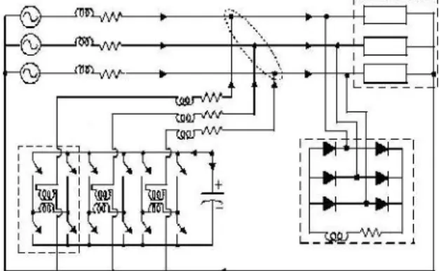
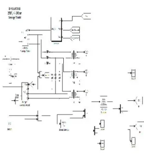
Many voltage source inverter (VSI) topologies have been used for DSTATCOM applications. The three phase H-bridge VSI topology has been chosen because of the presence of a single dc link capacitor (unbalance in capacitor voltages which may occur in topologies with two dc capacitors need not be considered), simplicity and independent current tracking in each phase. Fig.1 shows a three phase, four wire compensated system using H-bridge VSI based DSTATCOM.
Fig. 1: Three phase, four wire compensated system using H-bridge VSI based DSTATCOM.
The unbalanced and non-linear load used is also shown in the figure. The DSTATCOM has 12 IGBT switches with anti parallel diodes (not shown in the figure for the sake of clarity), a dc storage capacitor, three isolation transformers and three interface inductors. In modelling the system, the inductance and resistance of the isolation transformers can be included in Lf and Rf, the interface inductance and resistance. Since we
sinusoidal and stiff, Ls and Rs, the source impedances, are assumed to be negligible. Hysteresis band current control has been used for tracking the reference currents. As seen in Fig. 1, the DSTATCOM injects the reference filter currents generated using the symmetrical component theory at the Point of Common Coupling (PCC). For good current injection and thus compensation, maintaining the dc capacitor value close to the reference value is very important.
III. DC LINK PI CONTROL AND FUZZY SUPERVISION:
During load changes, there is some active power exchange between the DSTATCOM and the load. This leads to a reduction or an increase in the dc capacitor voltage. Using a PI-controller, the Ploss term in (1) is controlled to ensure that the dc capacitor voltage does not deviate from the reference value. The control output of a PI controller is given by (2).
ploss=kp(vdc ref
–vdc)+ki⌡(vdc ref
-vdc)dt
The input to the PI controller is the error in the dc link voltage and the output is the value of Ploss. The value of Plossdepends on the value of Kp, Ki and the error in dc link voltage. Thus, it is important to tune K p and Kiproperly. Because of the inherent non-linearity and complexity of the system, it is difficult to tune the gains of the controller. It is usually done by trial and error. The base values of K p and Ki have been designed using the energy concept proposed in [7]. Also, it has been shown in literature that fuzzy supervision can improve the performance of PID controllers in nonlinear systems. However, these mostly deal with set-point changes in control applications. The derivative control term is not used because improvement in stability may or may not be obtained when used only with proportional control and if it is used with integral control as well, tuning for good performance is difficult [13]. The design of a fuzzy system is highly system specific and requires in-depth knowledge of the system and the various parameters that can be controlled for good performance. The design of a fuzzy supervisor for dc link PI control in a DSTATCOM is given in the next section
IV. DESIGN OF THE FUZZY LOGIC SUPERVISOR FOR PI-CONTROLLER:
conditions vary; further tuning may be necessary for good performance. Since many processes are complicated and nonlinear, fuzzy control seems to be a good choice. Literature shows many approaches where the PI controller has been replaced by a fuzzy controller. However, instead of completely modifying the control action, it is sufficient to use an additional level of control by supervising the gains using fuzzy techniques to improve the performance of the system.
A PI controller is preferred to regulate the dc link voltage as the presence of the integral term ensures zero steady state error. The dc link capacitor voltage waveform contains a ripple because according to the instantaneous symmetrical component theory, which is used in this work, the compensator supplies the oscillating part of the active power also. Thus there is always a zero average oscillating power exchange between the compensator and the load. This ripple can be seen in the simulation results in Fig. 9. The fuzzy controller scaling has been designed to give a good output irrespective of the presence of the ripple during the transient period. Some of the main aspects of fuzzy controller design are choosing the right inputs and outputs and designing each of the four components of the fuzzy logic controller shown in Fig. 2. Each of these will be discussed in the subsections below: Also, the fuzzy controller is activated only during the transient period and once the value of the dc link voltage settles down, the controller gains are kept constant at the steady state value.
Fig. 2: Fuzzy controller architecture.
A. Inputs and Outputs:
The inputs of the fuzzy supervisor have been chosen as the error in dc link voltage and the change in error in dc link voltage.
Kperr(i)=vdcref _vdc(i) (3)
derr(i)=err(i)–err(i-1) (4)
In (3) and (4) above, e(i) is the error and e (i) is the change in error in the Ithiteration. Vdc ref is the reference dc link voltage and vdc (i) is the dc link voltage in the Ithiteration. The outputs of the fuzzy
supervisor are chosen as the change in Kp value and the change in Ki value.
Kp= Kp ref+Kp (5)
Ki=Ki ref+Ki (6)
Kp ref and Ki ref are the steady state values determined by the method specified in and Kp and
Ki are the outputs of the fuzzy logic supervisor.
B. Fuzzification:
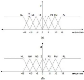
The fuzzification interface modifies the inputs to a form in which they can be used by the inference mechanism. It takes in the crisp input signals and assigns a membership value to the membership function under whose range the input signal falls. Typical input membership functions are triangular trapezoidal or exponential. Seven triangular membership functions have been chosen:
NL (Negative Large), NM (Negative Medium), NS
(Negative Small), Z (Zero), PS (Positive Small),
PM (Positive Medium) and PL (Positive Large) for
both error (err) and change in error. The input membership functions are shown in Fig. 3. The tuning of the input membership function is done based on the requirement of the process. Each membership function has a membership value belonging to [0 1]. It can be observed that for any value of error or change in error, either ne or two membership functions will be active for each.
Fig.3(a): Membership functions for error input. (b) Membership functions for change in error input
C. Inference Mechanism:
a) Based on the active membership functions in error and the change in error inputs, the rules which apply for the current situation are determined.
b) Once the rules which are on are determined, the certainty of the control action is ascertained from the membership values. This is known as premise quantification.
Thus at the end of this process, we shall have a set of rules each with a certain certainty of being valid. The database containing these rules is present in the rule base from which the control action is obtained. The rule base will be discussed in the next section. An example of a rule is given in (7). The terms PL and PM are the membership functions for error and for change in error respectively.
IF
"error" is PL (positive large)
"change in error" is PM (positive medium) THEN
" Kp" is L ( Large Kp )
" Ki" is SKi ( Small Ki )
The minimum operation is used to determine the certainty called μpremise of the rule formed by their combination. D. The Rule Base Designing the rule base is a vital part in designing the controller. It is important to understand how the rule base has been designed. Fig. 4 shows a typical dc link voltage waveform after an increase in the load without the inherent ripple due to compensation. The waveform has been split into various parts depending on the sign of error and change in
Fig. 4: Typical dc link voltage waveform after a load change.
error. The rules in the rule base are designed based on which part of the graph the waveform is in. The important points involved in the design of the rule base are the following:
a) If the error is large and the change in error shows the dc link waveform deviating away from the reference, then increase Kp.
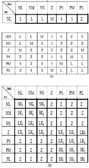
b) If the waveform is approaching the reference value, then increase the Ki value to reduce overshoot and improve settling time Keeping these aspects in mind, two rule base matrices have been developed for Kp and Ki.
Fig. 5(a) gives the rule base matrix for Kp and Fig. 5(b) gives the rule base matrix for Ki. The output membership functions for the proportional gain are Lki, Ski and Z and the output membership functions for integral gain are L, M, S and Z. These matrices provide rules such as the example seen in for all possible combinations of the membership functions for error and change in error. Thus, using information from the rule base, the rule and its certainty is determined by the inference mechanism. The method to convert the fuzzy result to crisp control action is called defuzzification. This is explained in the next section.
The inference mechanism provides us with a set of rules each with a μpremise. The defuzzification mechanism considers these rules and their respective μpremise values, combines their effect and comes up with a crisp, numerical output. Thus, the fuzzy control action is transformed to a non fuzzy control action. The ‘centre of gravity’ method has been used in this work for this. If we use this method, the resultant crisp output is sensitive to all of the active fuzzy outputs of the inference mechanism. Fig. 6(a) and Fig. 6(b) show the output membership functions chosen for Kp and Ki.
Fig. 6(a): Output membership function for Kp (b) Output membership function Ki.
According to this method the weighted mean of the center values of the active output membership functions is taken as the output, the weights being the area under the line representing the.μpremise.
V. SIMULATION STUDY AND RESULTS:
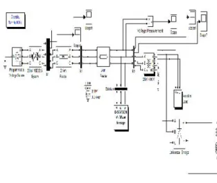
Fig. 1 shows the compensated system using a H-bridge VSI based DSTATCOM. This has been simulated in MATLAB. All switches shown in Fig. 1. are considered ideal. The ac load is a three phase unbalanced load and a three phase diode bridge rectifier feeding an inductive R-L load. The parameters of the system are given in Table 1. Since the average load power is supplied by the source, the following holds true.
VsaLla+VsbLlb+VscLlc=Pl avg (6)
To compute Plavg a moving average filter for half a cycle has been used. In steady state, at each zero crossing of the phase a voltage, Ploss is generated using the PI controller.
Fig.7: Simulink model with DSTATCOM
Fig.7.(a): Load Voltage (PCC voltage) waveforms with DSTATCOM
Fig. 7.(b): Dc Link voltage of DSTATCOM
There is a considerable variation in the DC link voltage due to sudden voltage swell created at 0.4sec as shown in Fig. 10.For good compensation , it is important that capacitor voltage remains as close to the reference value as possible. This is done by using Fuzzy logic supervision of Dc link PI control which will be discussed in next case.
Fig. 8: Fuzzy logic supervisor implemented for DC link PI control
Fig.8.(a): Load voltage (PCC voltage) with Fuzzy supervision of Dc Link PI control.
Fig.8.(b): DC link Voltage with Fuzzy supervision
By comparing the DC link voltages without Fuzzy supervision and with Fuzzy supervision from Fig.8(a) and Fig.8(b) respectively the following conclusions are drawn.
VI.CONCLUSIONS:
A fuzzy logic supervisor to the dc link PI controller of the DSTATCOM has been proposed. The supervisor varies the gain of the PI controller during the transient period in a way that improves performance. The system has been modelled and simulated in the MATLAB technical environment.
The performance of the dc link and compensation were observed with and without the fuzzy supervisor. Simulation result show a 50-60% reduction in voltage deviation of the dc link voltage with faster settling time. Good compensation has been observed. Thus, through simulation studies, the implementation of a fuzzy supervisor for DC link voltage control in a DSTATCOM for load compensation has been demonstrated.
VII. REFERENCES:
[1] M.Pavani and Dr.I.Venu gopal “DC Link capacitor voltage of D-STATCOM with Fuzzy logic Supervision”page:1-6,2012.
[2] A. Ghosh and G. Ledwich; “Power Quality enhancement using custom power devices,” Kluwer Academic Publishers, Boston, 2011
[3] N. Hingorani, “Introducing Custom Power ,”
IEEE Spectrum. Vol. 32,no. 6 pp. 41-48,2011.
[4] K. Karthikeyan and Mahesh Kumar, “A three phase DSTATCOM compensating AC and DC loads with Fast Dynamic Response,” IEEE Canadian Conf. on Elec. and Comp. Engineering,
pp. 1199–1202, 2008
[5] A. Ajami and H.S. Hosseini, “Application of a Fuzzy Controller for Transient Stability Enhancement of AC Transmission System by STATCOM,” International Joint Conference SICE-ICASE, pp. 6059-6063, 2006
[6] S. Iyer, A. Ghosh and A. Joshi, “Inverter Topologies for DSTATCOM applications - a simulation study,” Elsevier, Vol. 75 pp. 161 175,
2005
[7] K. H. Ang, G. Chong and Y. Li, “PID control system analysis, design and technology,” IEEE Trans. on Control Systems Technology, Vol. 13, no. 4, 559-576, 2005
[8] H. Kim, F. Blaabjerg, B. B. Jemsen and J. Choi, “Instantaneous powercompensation in three-phase systems by using p-q-r theory,” IEEE Trans. on Power Electronics, Vol. 17, no 5, 701-709, 2002.
[9] B. N. Singh, A. Chandra and K. Al-Haddad, “DSP-based indirect current- controlled STATCOM. I. Evaluation of current control techniques,” IEE Proc. on Electric Power Applications, Vol. 147, pp. 107-112, 2000
power distribution system,”IEEE Trans. on Power Delivery, Vol. 15, no. 1 pp. 417-422, 2000.
[11] K. M. Passino and S. Yurkovich; “Fuzzy Control”Addison-Wesley, 1998
[12] R. P. Copeland and K. S. Rattan, “A fuzzy logic supervisor for PID control of unknown systems,” Proc. of the 1994 IEEE International Symposium on Intelligent Control, pp. 22-26, 1994.
[13] D. Abramovitch, “Some crisp thoughts on fuzzy logic,”American Control Conference, Vol. 1
pp. 168-172, 1994.
[14] S. Tzafestas and N. P. Papanikolopoulos, “Incremental fuzzy expert PID control,” IEEE Transactions on Industrial Electronics, Vol. 37, pp.
365- 371, 1990.