Abstract— Now-a-days Induction Motor plays a vital
role in Automation Industries for variable speed applications. The speed information which is important for control purposes could be extracted using speed sensing devices like tachogenerators, sensors & incremental encoders. However, the present of speed sensing devices itself has reduced the drive reliability as well as increased the drive’s size & cost. This situation has put the IM drive at disadvantage when talking about its good dynamic response and performance for variable speed control. Its predecessor, the dc machine is always a good choice but with the development of several new methods to extract the speed or position signal, it has put the IM drive as a better choice for variable speed control. This technique is called “speed sensorless technique”, which refers to the elimination of the shaft sensor used to obtain the speed information. Advantages of speed senseless IM Drive includes reduce hardware complexity, reduces drive size & cost, bettor noise immunity, increases reliability and required less maintenance. The aim of this thesis is to develop the speed sensorless estimation concept via implementation of Fuzzy contorlled Model Reference Adaptive System (MRAS) in vector controlled induction motor drive operating without a speed or position sensor but having a dynamic performance comparable to a sensored vector drive. Vector control of induction motor is based upon the field-oriented co-ordinates aligned in the direction of the rotor m.m.f. However, there is no direct means of measuring the rotor flux linkage position ρ and therefore an observer is needed to estimate ρ for the implementation of sensorless vector control. First the Dynamic model of induction machine was developed in the arbitrary reference frame. With the help of synchronous reference frame model the indirect field oriented vector control, which is very popular and convenient method in real time implementation was developed. Third, Fuzzy based Model Reference Adaptive System is studied as a state estimator. Simulation results of Vector Control and Sensorless Control of induction motor using fuzzy based MRAS technique were carried out by using Matlab/Simulink and from the analysis of the simulation results, the transient and steady state performance of the drive have been presented and analyzed.
Index Terms—Field Oriented control (FOC), Fuzzy controller
(FC), Induction motor (IM), model Reference Adaptive Control (MRAC), Vector Control.
I. INTRODUCTION
Induction motor (IM) can be considered as the ‗workhorse‘ of the industry because of its special features such as low cost, high reliability, low inertia, simplicity and ruggedness. Even today IMs especially the squirrel cage type, are widely used for
single speed applications rather than variable speed applications due to the complexity of controlling algorithm and higher production cost of IM variable speed drives. However, there is a great interest on variable speed operation of IM within the research community mainly because IMs can be considered as a major industrial load of a power system. On the other hand the IMs consume a considerable amount of electricity generated.[2] The majority of IMs are operated at constant speed, determined by the pole pair number and the stator supply frequency. The two names for the same type of motor, induction motor and asynchronous motor, describe the two characteristics in which this type of motor differs from DC motors and synchronous motors. Induction refers to the fact that the field in the rotor is induced by the stator currents, and asynchronous refers to the fact that the rotor speed is not equal to the stator frequency. No sliding contacts and permanent magnets are needed to make an IM work, which makes it very simple and cheap to manufacture. As motors, they rugged and require very little maintenance. However, their speeds are not as easily controlled as with DC motors. They draw large starting currents, and operate with a poor lagging factor when lightly loaded. Among model-based estimation techniques, the model reference adaptive system (MRAS) approach has found widespread application in FOC IM drives for reasons of simplicity and low computational effort [4]-[7]. The MRAS makes use of the redundancy of two machine models of different structures that estimate the same state variable on the basis of different sets of input variables. Use of the reactive power, stator current or back e.m.f. in the MRAS approach to produce the speed error correction signal has been reported [4]-[6]. Furthermore, simultaneous MRAS based rotor speed estimation and online parameters tuning is introduced [6][7]. However, such implementations exhibit stability problems when operating at low stator frequencies and under certain operating conditions [4]. Another concern in the sensorless drives is the closed loop control and its interaction with the rotor speed and flux estimators. In case of indirect FOC, the rotor field angle is determined by the rotor speed and slip gain. Therefore, the system performance is greatly affected by the speed estimation errors and rotor time constant variations. On the other hand, most direct stator FOC techniques determine the coordinate transformation angle on the basis of the estimated stator flux. Accordingly, the field orientation is strongly dependent on the performance of the stator flux observer.
Predictive Vector Control Based Induction Motor
Drive using Fuzzy Controller
G. Victor Raj
1, K.Venkataramana
2, V.Chaitanya
31
PG Scholar, Dept. of EEE, VITAM College of Engineering, Visakhapatnam, AP, India 2
Assistant Professor, Dept. of EEE, VITAM College of Engineering, Visakhapatnam, AP, India 3
II. MODELLINGOFINDUCTIONMOTOR The control and speed sensorless estimation of IM drives is a vast subject. Traditionally, the IM has been used with constant frequency sources and normally the squirrel-cage machine is utilized in many industrial applications, A typical construction of a squirrel cage IM is illustrated in Figure 1. Its main advantages are the mechanical and electrical simplicity and ruggedness, the lack of rotating contacts (brushes) and its capability to produce torque over the entire speed range.
Fig1: A cut-away view of a squirrel cage IM
Before going to analyze any motor or generator it is very much important to obtain the machine in terms of its equivalent mathematical equations. Traditional per phase equivalent circuit has been widely used in steady state analysis and design of induction motor, but it is not appreciated to predict the dynamic performance of the motor. The dynamics consider the instantaneous effects of varying voltage/currents, stator frequency, and torque disturbance. The dynamic model of the induction motor is derived by using a two-phase motor in direct and quadrature axes. This approach is desirable because of the conceptual simplicity obtained with two sets of windings, one on the stator and the other in the rotor. The equivalence between the three phase and two phase machine models is derived from simple observation, and this approach is suitable for extending it to model an n-phase machine by means of a two phase machine.
A Reference Frames
The required transformation in voltages, currents, or flux linkages is derived in a generalized way. The reference frames are chosen to be arbitrary and particular cases, such as stationary, rotor and synchronous reference frames are simple instances of the general case. R.H. Park, in the 1920s, proposed a new theory of electrical machine analysis to represent the machine in d – q model. He transformed the stator variables to a synchronously rotating reference frame fixed in the rotor, which is called Park‘s transformation. He showed that all the time varying inductances that occur due to an electric circuit in relative motion and electric circuits with varying magnetic reluctances could be eliminated. In 1930s, H.C Stanley showed that time varying Inductances in the voltage equations of an induction machine due to electric circuits in relative motion can be eliminated by transforming the rotor variables to a stationary reference frame fixed on the stator. Later, G. Kron proposed a transformation of both stator and rotor variables to a synchronously rotating reference that moves with the rotating magnetic field.
B Axes Transformation
We know that per phase equivalent circuit of the induction motor is only valid in steady state condition. Nevertheless, it
doesn‘t hold good while dealing with the transient response of the motor. In transient response condition the voltages and currents in three phases are not in balance condition. It is too much difficult to study the machine performance by analyzing the three phases. In order to reduce this complexity the transformation of axes from 3 – Φ to 2 – Φ is necessary. Another reason for transformation is to analyze any machine of n number of phases. Thus, an equivalent model is adopted universally, that is ‗d – q model‘.
Fig 2: 3- to 2- Transformation
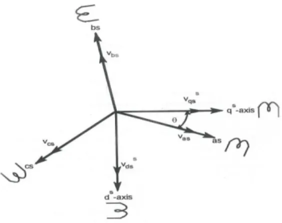
Consider a symmetrical three-phase induction machine with stationary as-bs-cs axis at 2/3 angle apart. Our goal is to transform the three-phase stationary reference frame (as-bs-cs) variables into two-phase stationary reference frame (ds-qs) variables. Assume that ds- qs are oriented at angle as shown in fig: 2.
The voltages qss s
ds
andv
v
can be resolved into as-bs-cs components and can be represented in matrix from as, s os s ds s qs cs bs as V V V V V V 1 ) 120 sin( ) 120 cos( 1 ) 120 sin( ) 120 cos( 1 sin cos 0 0 0 0 ( 2.1 )
The corresponding inverse relation is
cs bs as o o o o s os s ds s qs V V V Sin Sin Sin Cos Cos Cos V V V 5 . 0 5 . 0 5 . 0 ) 120 ( ) 120 ( ) 120 ( ) 120 ( 3 2 (2.2)
Here vossis zero-sequence component, convenient to set = 0 so that qs axis is aligned with as-axis. Therefore ignoring zero-sequence component, it can be simplified as-
as cs bs as s qs
v
v
v
v
V
3
1
3
1
3
2
(2.3) 2.3 cs bs s dsv
v
V
3
1
3
1
(2.4) 2.4Equations 2.3 & 2.4 consistively called as Clark Transformation.
Figure 3 shows the synchronously rotating de-qe axes, which rotate at synchronous speed we with respect to the ds-qs axes and
the angle . The two-phase ds-qs windings are transformed into the hypothetical windings mounted on the de-qe axes. The voltages on the ds-qs axes can be transformed (or resolved) into the de-qe frame as follows:
Fig 3: stationary frame ds-qs to synchronously rotating frame de-qe transformation
Constitutively eq 2.5 and 2.6 are known as Park Transformation.
For convenience, the superscript ‗e‘ has been dropped from now on from the synchronously rotating frame parameters. Again, resolving the rotaing frame parameters into a stationary frame, the relations are
Constitutively eq 2.7 and 2.8 are known as Inverse Park Transformation.
B Dynamic equations of induction machine
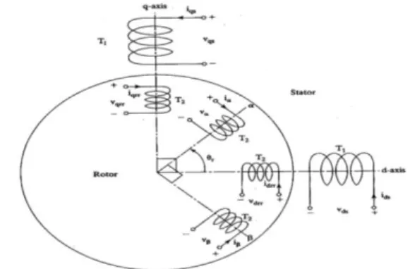
Generally, an IM can be described uniquely in arbitrary rotating frame, stationary reference frame or synchronously rotating frame. For transient studies of adjustable speed drives, it is usually more convenient to simulate an IM and its converter on a stationary reference frame. Moreover, calculations with stationary reference frame are less complex due to zero frame speed. For small signal stability analysis about some operating condition, a synchronously rotating frame which yields steady values of steady-state voltages and currents under balanced conditions is used. The two-phase equivalent diagram of three-phase induction motor with stator and rotor windings referred to d – q axes is shown in Fig 4.
The windings are spaced by 90o electrical and rotor winding
, is at an angle θr from the stator d-axis. It is assumed that the
d axis is leading the q axis in clockwise direction of rotation of the rotor. If the clockwise phase sequence is dq, the rotating magnetic field will be revolving at the angular speed of the
supply frequency but counter to the phase sequence of the stator supply.
Fig 4: Two-phase equivalent diagram of induction motor Therefore the rotor is pulled in the direction of the rotating magnetic field i.e. counter clockwise, in this case. The currents and voltages of the stator and rotor windings are marked in figure 4. The number of turns per phase in the stator and rotor respectively are T1 and T2. A pair of poles is assumed for this
figure. But it is applicable with slight modification for any number of pairs of poles if it is drawn in terms of electrical degrees. Note that r is the electrical rotor position at any
instant, obtained by multiplying the mechanical rotor position by pair of poles. The terminal voltages of the stator and rotor windings can be expressed as the sum of the voltage drops in resistances, and rate of change of flux linkages, which are the products of currents and inductances.
From the above figure the terminal voltages are as follows,
Vqs = Rqiqs + p (Lqqiqs) + p (Lqdids) + p (Lqi) + p (Lqi)
Vds = p (Ldqiqs) + Rdids + p (Lddids) + p (Ldi) + p (Ldi)
V = p (Lqiqs) + p (Ldids)+ Ri + p (Li) + p (Li)
V = p (Lqiqs) + p (Ldids) + p (Li) + R i+ p (Li)
Where p is the differential operator d/dt, and vqs, vds are
the terminal voltages of the stator q axis and d axis. V, V are
the voltages of rotor and windings, respectively. iqs and ids
are the stator q axis and d axis currents. Whereas iand i are
the rotor and winding currents, respectively and Lqq, Ldd,
L and L are the stator q and d axis winding and rotor and
winding self-inductances, respectively.
The following are the assumptions made in order to simplify the equation
i. Uniform air-gap
ii. Balanced rotor and stator windings with sinusoidally distributed mmfs
iii. Inductance in rotor position is sinusoidal and iv. Saturation and parameter changes are
neglected
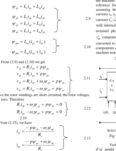
The dynamic equations of the induction motor in any reference frame can be represented by using flux linkages as variables. This involves the reduction of a number of variables in the dynamic equations. Even when the voltages and currents
are discontinuous the flux linkages are continuous. The stator and rotor flux linkages in the stator reference frame are defined as ds m dr r dr qs m qr r qr dr m ds s ds qr m qs s qs
i
L
i
L
i
L
i
L
i
L
i
L
i
L
i
L
2.9 2.17)
(
)
(
dr ds m dm qr qs m qmi
i
L
i
i
L
2.10From (2.9) and (2.10) we get
qr dr r qr r qr dr qr r dr r dr qs qs s qs ds ds s ds
p
i
R
v
p
i
R
v
p
i
R
v
p
i
R
v
2.11Since the rotor windings are short circuited, the rotor voltages are zero. Therefore
0
0
qr dr r qr r dr qr r dr rp
i
R
p
i
R
2.12 2.19 From (2.15), we have r dr r qr qr r qr r dr drR
p
i
R
p
i
2.13 2.20 By solving the equations 2.10, 2.11, 2.12 and 2.13 we get thefollowing equations
ds
(
v
ds
R
si
ds)
dt
2.14
qs
(
v
qs
R
si
qs)
dt
2.15 r r r ds m qr r r drsL
R
R
i
L
L
2.16
)
.(
.
s s r m dr s s ds dssL
R
L
sL
sL
R
v
i
2.17
)
.(
.
s s r m qr s s qs qssL
R
L
sL
sL
R
v
i
2.18T
e
p
L
m(
i
qsi
dr
i
dsi
qr2
2
3
) 2.19 or(
)
2
2
3
qr ds dr qs r m ei
i
L
L
p
T
2.20III. PRINCIPLEOFVECTORCONTROL The fundamentals of vector control can be explained, where the machine model is represented in a synchronously rotating reference frame. The inverter is omitted from the figure, assuming that it has unity current gain, i.e., it generates currents ia, ib, and ic as dictated by the corresponding command
currentsi*a,i*b, and i from the controller. A machine model *c
with internal conversions is shown on the right. The machine terminal phase currents ia, ib, ic are converted to isds and
s qs
i components by 3-2 transformation. These are then converted to synchronously rotating frame by the unit vector components cos e and sin e before applying them to the de- qe
machine model.
Fig 5: Basic block diagram of vector control
Vector control implementation principle with machine ds-qs model as shown. The controller makes two stages of inverse transformation, as shown, so that the control currents
* ds
i and i*qs correspond to the machine currents ids and iqs,
respectively. In addition, the unit vector assures correct alignment of ids current with the flux vector
^ r
and iqs
perpendicular to it, as shown. It can be noted that the transformation and inverse transformation including the inverter ideally do not incorporate any dynamics, and therefore, the response to ids and iqs is instantaneous (neglecting
computational and sampling delays).
The schematic diagram of control strategy of induction motor with sensorless control is shown in Fig 6. Sensor less control induction motor drive essentially means vector control without any speed sensor [5, 17]. The inherent coupling of motor is eliminated by controlling the motor by vector control, like in the case of as a separately excited motor.
The inverter provides switching pulses for the control of the motor. The flux and speed estimators are used to estimate the flux and speed respectively. These signals then compared with reference values and controlled by using the Fuzzy controller.
Fig 6: Block Diagram of Sensorless Control of Induction Motor
IV. MODEL REFERENCING ADAPTIVE SYSTEM (MRAS)
Tamai [5] has proposed one speed estimation technique based on the Model Reference Adaptive System (MRAS) in 1987. Two years later, Schauder [6] presented an alternative MRAS scheme which is less complex and more effective. The MRAS approach uses two models. The model that does not involve the quantity to be estimated (the rotor speed, ωr) is considered as the reference model. The model that has the quantity to be estimated involved is considered as the adaptive model (or adjustable model). The output of the adaptive model is compared with that of the reference model, and the difference is used to drive a suitable adaptive mechanism whose output is the quantity to be estimated (the rotor speed). The adaptive mechanism should be designed to assure the stability of the control system. A successful MRAS design can yield the desired values with less computational error (especially the rotor flux based MRAS) than an open loop calculation and often simpler to implement. The model reference adaptive system (MRAS) is one of the major approaches for adaptive control [6]. The model reference adaptive system (MRAS) is one of many promising techniques employed in adaptive control. Among various types of adaptive system configuration, MRAS is important since it leads to relatively easy- to-implement systems with high speed of adaptation for a wide range of applications.
Fig 7: Basic identification structure and their correspondence with MRAS
V. FUZZY LOGIC CONTROL
L. A. Zadeh presented the first paper on fuzzy set theory in 1965. Since then, a new language was developed to describe the fuzzy properties of reality, which are very difficult and sometime even impossible to be described using conventional methods. Fuzzy set theory has been widely used in the control area with some application to power system [5]. A simple fuzzy logic control is built up by a group of rules based on the human knowledge of system behavior. Matlab/Simulink simulation model is built to study the dynamic behavior of converter.
Furthermore, design of fuzzy logic controller can provide desirable both small signal and large signal dynamic performance at same time, which is not possible with linear control technique. Thus, fuzzy logic controller has been potential ability to improve the robustness of compensator.
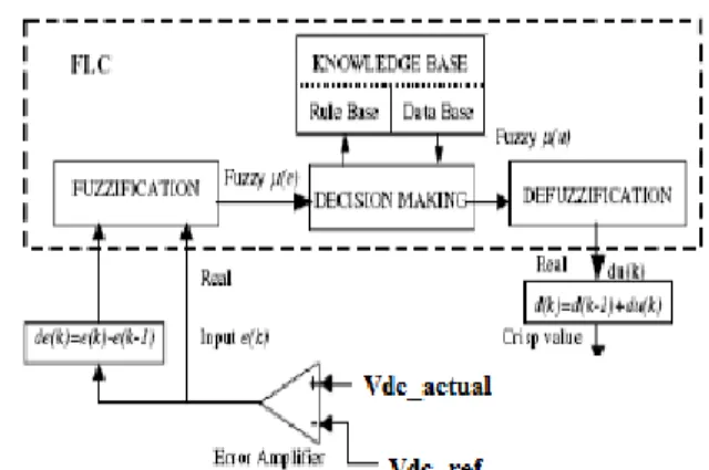
Fig.8. Block diagram of the Fuzzy Logic Controller (FLC) for proposed converter.
The basic scheme of a fuzzy logic controller is shown in Fig.8 and consists of four principal components such as: a fuzzy fication interface, which converts input data into suitable linguistic values; a knowledge base, which consists of a data base with the necessary linguistic definitions and the control rule set; a decision-making logic which, simulating a human decision process, infer the fuzzy control action from the knowledge of the control rules and linguistic variable definitions; a de-fuzzification interface which yields non fuzzy control action from an inferred fuzzy control action [10].
Fig.9. Membership functions for Input, Change in input, Output.
Rule Base: the elements of this rule base table are determined based on the theory that in the transient state, large errors need coarse control, which requires coarse in-put/output variables; in the steady state, small errors need fine control, which requires fine input/output variables as shown in Fig.9.
TABLE I: Rule Table
IV. VECTORCONTROLOFINDUCTIONMOTOR The Vector Control or Field orientation control of induction motor is simulated on MATLAB/SIMULINK - platform to study the various aspects of the controller. The actual system
can be modeled with a high degree of accuracy in this package.. This chapter discusses the realization of vector control of induction motor using Simulink blocks. Fig.10 shows the Vector controlled Induction Motor block simulink diagram for simulation.
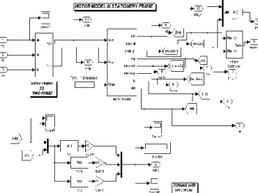
Fig 10: Simulink Model of Vector Controlled Induction motor A Induction Motor Model
The motor is modeled in stator reference frame. The dynamic equations are given using these equations we can develop the induction motor model in stator reference frame. Fig 11 shows the simulink block diagram for motor model. Inputs to this block are direct and quadrature axes voltages and load torque. The outputs are direct and quadrate axis rotor fluxes, direct and quadrature axes stator currents, electrical torque developed and rotor speed.
Fig.11: Simulink block diagram for induction motor model B Sensorless Control of Induction Motor
The Sensorless control of induction motor using Model Reference Adaptive System (MRAS) is simulated on MATLAB/SIMULINK - platform to study the various aspects of the controller.. Here we are going to discuss the realization of Sensorless control of induction motor using MRAS for simulink blocks.. Main subsystems are the 3-phase to 2-phase transformation, 2-phase to 3-phase transformation, induction
motor model, Model Reference Adaptive System (MRAS) and optimal switching logic & inverter.
Fig 12: Simulink root block diagram of Sensorless control of induction motor using MRAS
C Simulation Of Fuzzy controlled Model Refernce Adaptive System (MRAS)
Simulink block diagram Model Referencing Adaptive System (MRAS) Which is consists Two blocks one is called Reference Model and other is Adaptive Model. The voltage model‘s stator-side equations, are defined as a Reference Model and the simulink block diagram of Reference Model is shown in Fig 12. The Adaptive Model receives the machine stator voltage and current signals and calculates the rotor flux vector signals, as indicated by equations, which is shown in Fig 13. By using suitable adaptive mechanism the speed ωr, can be estimated and taken as feedback.
Fig 13: Simulink block diagram for Fuzzy controlled Model Referencing Adaptive System
VI. SIMULATION RESULTS
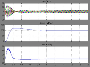
The simulation of Vector Control of Induction Motor is done by using MATLAB/SIMULINK. The results for different cases are given below.
Fig 13: 3-phase currents, Speed, and Torque for no-load reference speed of 100 rad/sec
Fig 14: Reference speed, Rotor Speed, Slip Speed Respectively Reference speed = 100 rad/sec; Load torque of 15 N-m is applied at t = 1.5 sec
Fig 15: 3-phase currents, Speed, and Torque for no-load reference speed of 100 rad/sec
VIICONCLUSION
In this thesis, Sensorless control of induction motor using Fuzzy Controlled Model Reference Adaptive System (FC-MRAS) technique has been proposed. Sensorless control
gives the benefits of Vector control without using any shaft encoder. In this thesis the principle of vector control and Sensorless control of induction motor is given elaborately. The mathematical model of the drive system has been developed and results have been simulated. Simulation results of Vector Control and Sensorless Control of induction motor using FC-MRAS technique were carried out by using Matlab/Simulink and from the analysis of the simulation results, the transient and steady state performance of the drive have been presented and analyzed. From the simulation results, it can be observed that, in steady state there are ripples in torque wave and also the starting current is high. Thus by using sensorless control we can get the accurate speed than that of vector control without shaft encoder. Hence by using this proposed technique, we can reduce the cost of drive i.e. shaft encoder‘s cost, we can also increase the ruggedness of the motor as well as fast dynamic response can be achieved.
VIII REFERENCES
[1] S. Chen, B. Mulgrew, and P. M. Grant, ―A clustering technique for digital communications channel equalization using radial basis function networks,‖ IEEE Trans. on Neural Networks, vol. 4, pp. 570-578, July 1993.
[2] J. U. Duncombe, ―Infrared navigation—Part I: An assessment of feasibility,‖ IEEE Trans. Electron Devices, vol. ED-11, pp. 34-39, Jan. 1959.
[3] C. Y. Lin, M. Wu, J. A. Bloom, I. J. Cox, and M. Miller, ―Rotation, scale, and translation resilient public watermarking for images,‖ IEEE Trans. Image Process., vol. 10, no. 5, pp. 767-782, May 2001.
[4] 1. Abbondanti, A. and Brennen, M.B. (1975). Variable speed induction motor drives use electronic slip calculator based on motor voltages and currents. IEEE Transactions on Industrial Applications, vol. IA-11, no. 5: pp. 483-488. [5] 2. Nabae, A. (1982). Inverter fed induction motor drive
system with and instantaneous slip estimation circuit. Int. Power Electronics Conf., pp. 322-327.
[6] 3. Jotten, R. and Maeder, G. (1983). Control methods for good dynamic performance induction motor drives based on current and voltages as measured quantities. IEEE Transactions on Industrial Applications, vol. IA-19, no. 3: pp. 356-363.
[7] 4. Baader, U., Depenbrock, M. and Gierse, G. (1989). Direct self control of inverter-fed induction machine, a basis for speed control without speed measurement. Proc. IEEE/IAS Annual Meeting, pp. 486-492.
[8] 5. Tamai, S. (1987). Speed sensorless vector control of induction motor with model reference adaptive system. Int. Industry Applications Society. pp. 189-195.
[9] 6. Griva, G., Profumo, F., Illas, C., Magueranu, R. and Vranka, P. (1996). A unitary approach to speed sensorless induction motor field oriented drives based on various model reference schemes. IEEE/IAS Annual Meeting, pp. 1594-1599.
[10] 7. Viorel, I. A. and Hedesiu, H. (1999). On the induction motors speed estimator‘s robustness against their parameters. IEEE Journal. pp. 931-934.
[11] 8. K. S. Narendra, J. Balakrishnan, and M. K. Ciliz, ―Adaptation and learning using multiple models, switching, and tuning,‖ IEEE Contr.Syst. Mag., June 1995.
[12] 9. J. Holtz and Quan, J. Quan, ‗Sensorless vector control of induction motors at very low speed using a nonlinear inverter model and parameter identification,‘ IEEE Trans. On Ind. Appl.,Vol. 38, No. 4, pp. 1087-1095, 2002. [13] 10. H. M. Kojabadi, L.Chang, and R.Doraiswami,‗ A
MRAS-Based Adaptive Pseudoreduced-Order Flux Observer for Sensorless Induction Motor Drives,‘ IEEE Trans. On Power Electr., Vol. 20, No. 4, pp. 930-938, 2005.
[14] 11. O. S.Ebrahim, M. M. Negm and M. Z. Youssef, ‗An improved DTC scheme for The AC Drives based on optimal preview control technique,‘ ISIE2006, pp. 2194-2199, 2006.