3226 ISSN: 2278 – 7798 All Rights Reserved © 2014 IJSETR
Abstract— Electrical distribution system is the basic stage to transfer of electrical power from the central generating station to the consumers. Among these systems, radial distributions system is essential because of the effective coordination of their protective system. Minimization of active power losses is one of the essential in distribution system. Therefore, this paper proposes for capacitor placement and sizing in radial distribution system to reduce the power losses and to improve the voltage profile using Fuzzy Expert System (FES). Before installing the capacitor, a load flow program based on complex power flow method is run to obtain the present system. The above method is tested on a 35 bus, 28 lines from Mandalay Electricity Supply Board (MESB) with multilevel of loads.
Index Terms— Capacitor location and sizing, fuzzy expert system (FES), ETAP.
I. INTRODUCTION
Electrical distribution systems are an essential part of the electrical power system. In order to transfer electrical power from an alternating current or a direct current source to the place where it will be used, some type of distribution network must be utilized [4]. Since distribution systems account for up to 90% of all losses reduction problems, improving loss reduction of distribution system is the key to improving system stability [17]. Generally the improvement in distribution system is carried out by three techniques, system reconfiguration, reactive power compensation and implementation of distributed generation. In this paper, reactive power compensation is emphasized.
The reactive optimization problem in distribution systems is usually formulated as optimization of the position and size of capacitor banks in order to minimize power or energy loss and investment in reactive support [17]. The economical benefits of installation capacitors in distribution systems are reduced energy and peak power losses, improved voltage regulation, released capacity of distribution feeders, released substation capacity, released transmission capacity and released generation capacity [17].
The power generation utilities aimed to raise operational efficiency to the possible extent by reducing the amount of losses in real power transmitted across the transmission lines, and also aim to maintain the quality of power supplied to users Shane, Electrical Power Department, Yangon Technological University,. Yangon, Myanmar, +959 250085965
Phoo Ngone Si, Electrical Power Department, Yangon
Technological University, Yangon, Myanmar, +959 420044054,
Su Su Win, Electrical Power Department, Yangon Technological University, Yangon, Myanmar, +959 5201973,
through voltage controlling within the permissible limits [1]. Therefore need to use shunt capacitors as effective tool has been grown towards optimal control of reactive power. Shunt capacitors are installed at suitable locations in large electric network for the improvement of voltage profile and to reduce power losses in the transmission and distribution lines [2]. At the present stage of research, load-flow on radial feeders is used to evaluate the losses of arbitrary solutions. Optimum capacitor placement is achieved using sophisticated methods such as neural networks, fuzzy logic, and Genetic Algorithms(GA) [9]. Fuzzy Set Theory(FST) provides a remedy for any lack of uncertainty in the data. Furthermore fuzzy logic has the advantage of including heuristic and representing engineering judgments into the capacitor allocation optimization process [3].
The power loss in a distribution system is significantly high because of lower voltage and hence high current, compared to that in a high voltage transmission system [4]. The pressure of improving the overall efficiency of power delivery has forced the power utilities to reduce the loss, especially at the distribution level. In this paper a radial distribution system is taken because of its simplicity [5].
Fuzzy based solution methods use fuzzy membership functions to model the actual systems. Identification of proper membership function is the most challenging task in the development of fuzzy based solution techniques. Node voltage measures and power loss in the network branches have been utilized as indicators for deciding the location and also the size of the capacitors in fuzzy based capacitor placement methods [5].
II. FLOWOFCAPACITORPLACEMENTANDSIZING
BASEDONFUZZYTECHINQUE
In the distribution feeder of MESB distribution network, the improvement of loss reduction is achieved by testing the load and impedance data. The impedance, real power and reactive power at the load of the radial distribution system are calculated. Simulations are run under 2 cases before and after installing a capacitor at each bus [6]. The algorithm for capacitor location finding & sizing are described by the following procedures.
1. Read line and load data of MESB radial distribution system.
2. To calculate bus voltages and power losses of the original distribution system, run the Load-Flow program without any capacitor
3. To calculate the Power Loss Index(PLI), take Bus Voltage (BV) of the original system. PLI at each
Fuzzy Algorithm for Capacitor Allocation
and Sizing in Radial Distribution system to
Reduce Losses
3227 ISSN: 2278 – 7798 All Rights Reserved © 2014 IJSETR
node is determined by using the formula given below: Where, X = Loss reduction Y = Minimum reduction Z = Maximum reduction n = Number of nodes
4. Install the same amount of reactive power at every node of power system.
5. The calculated losses reduction are linearly normalized between a "0" and"1" range with the largest losses reduction having a value of "1" and the smallest one having a value of "0", the values between "0" and "1" are the Power Losses Indices (PLI) [11].
6. Bus voltage and power losses index are the input values of Fuzzy Interface System(FIS) for finding the optimal locations of capacitor installation, the output of this controller.
7. After specifying the optimal locations of capacitor installation, the variables of BV and the amount of load in each load level are processes as input variables to the 2nd stage fuzzy controller to find the optimal sizes of capacitor value in MVA installed in each pre-specified optimal locations. The optimal value of capacitors represents the output, capacitor sizing, of fuzzy controller [11]. After finding of optimal sizes and optimal locations of distribution system, the load flow program is then performed again to know the impact of proposed solution method on the real power losses reduction and if the voltage profile within permissible limits ( value unit per of ± 5%) or not [11].
III. ALGORITHMADOPTEDFORLOADFLOW
SOLUTION
Load flow study is a technique that provides basic calculation procedure in order to determine the characteristics of power system under steady state condition. In this paper load flow study for 35-bus system is carried by using ETAP simulation software.
A
real time data in this system is collected for the month of June 2014. Conventional techniques for solving the load flow problem are iterative, using the Newton-
Raphson method.MESB system consists of nine power transformers, having capacity of two 100 MVA (230/33) kV, 100 MVA (230/132) kV, 60 MVA (230/33) kV, 80 MVA (132/33) kV, 31.5MVA (132/11) kV, 30MVA (132/33) kV, 18 MVA (132/11)kV and 15MVA (132/33) kV respectively with loads. Incoming voltage level is 230kV and 132kV the distribution voltage level is 33kV and 11kV. There are three transmission lines with 230kv and 132kv voltage level in this network. Capacitor installing of MESB is tested by fuzzy algorithm.
Fig.1 One line diagram of test case system
IV. IMPLEMENTATIONOFFUZZYALGORITHMFOR
CAPACITORPLACEMENT
For determining the suitability of capacitor placement at a particular node, a set of multiple-antecedent fuzzy rules have been established. The inputs to the rules are the voltage and power loss indices, and the output consequent is the suitability of capacitor placement. As given in table II, the consequents of the rules are in the shaded part of the matrix [17].
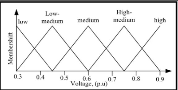
. The fuzzy variables, power loss reduction, voltage, and capacitor placement suitability are described by the fuzzy terms high, high-medium/normal, medium/normal, low-medium/normal or low. These fuzzy variables described by linguistic terms are described by the fuzzy terms high, high-medium/normal, medium/normal, low-medium/ normal or low [17].
These fuzzy variables described by linguistic terms are represented by membership functions. The membership functions are graphically shown in Fig.2, 3 & 4. The membership functions for describing the voltage have been created based on Mandalay Electric Supply Board(MESB) distribution systems. The membership functions for the PLI and CSI indices are created to provide a ranking. Therefore, partitions of the membership functions for the power and suitability indices are equally spaced apart.
0 0.1 0.2 0.3 0.4 0.5 0.6 0.7 0.8 0.9 1.0
Power loss index, (p.u)
M em be rs hi ft low
Low-medium medium mediumHigh- high
3228 ISSN: 2278 – 7798 All Rights Reserved © 2014 IJSETR
0.3 0.4 0.5Voltage, (p.u)0.6 0.7 0.8 0.9 M em be rs hi ft low Low-medium medium High-medium high
Fig. 3 Voltage magnitude membership function
0 0.1 0.2 0.3 0.4 0.5 0.6 0.7 0.8 0.9 1.0 Capacitor Suitable index, (p.u)
M em be rs hi ft low
Low-medium medium mediumHigh- high
Fig.4 Capacitor placement suitability membership function TABLE I
POWER LOSS INDEX,VOLTAGE INDEX AND CAPACITOR SUITABLE INDEX
TABLE.II
DECISION MATRIX FOR DETERMINING SUITABLE CAPACITOR LOCATION
V. IMPLEMENTATIONOFFUZZYALGORITHMFOR
CAPACITORSIZING
Fuzzy controller in this stage is used to get the optimal sizes which are installed in pre-specified location from above the capacitor placement result. The inputs of finding for capacitor size are the voltage and load indices, and the output is the size of capacitor in (MVA).The rules in this fuzzy controller are summarized in fuzzy rule table in Table III, the fuzzy variables of voltage, load, and capacitor size are
described by the fuzzy terms; Down Very Very Small(DVVS), Very Very Small(VVS), Very Small(VS),
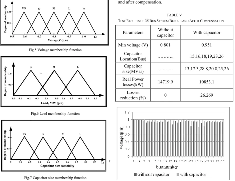
Small(S), Medium(M), Large(L) and Acceptable(A). These fuzzy variables described by linguistic terms are represented by membership functions, the membership function are graphically shown in Figures. The construction of these functions can be based on intuition, rank ordering or probabilistic methods [11].
The membership functions for describing the voltage have been established based on the ICE standards of acceptable operating voltage ranges for power systems value unit per of ± 5%. The membership functions for the load and capacitor size are established to provide a ranking. The minimum membership value for the two inputs propagates through the consequent and truncates the membership functions for the consequent of the rule [11].
TABLEIII
DECISION MATRIX FOR DETERMINING CAPACITOR SIZE
Bus No. PLI (Input 1) VI (Input 2) CSI (Output)
1 0.034846 0.801 0.299 2 0.165316 0.801 0.342 3 0.141005 0.802 0.349 4 0.233387 0.803 0.345 5 0.21799 0.813 0.359 6 0.222853 0.801 0.342 7 0.290113 0.801 0.405 8 0.235008 0.801 0.342 9 0.21799 0.801 0.342 10 0.235008 0.801 0.342 11 0.228525 0.801 0.342 12 0.226094 0.801 0.342 13 0.066451 0.801 0.329 14 0.431118 0.801 0.513 15 0.751216 0.801 0.75 16 0.832253 0.801 0.765 17 0.23906 0.803 0.345 18 0.569692 0.803 0.595 19 0.523501 0.803 0.595 20 0.47731 0.803 0.564 21 0.252026 0.803 0.349 22 0.222042 0.813 0.359 23 1 0.814 0.774 24 0.308752 0.814 0.441 25 0.179092 0.813 0.359 26 0.671799 0.801 0.665 27 0.288493 0.801 0.403 28 0.410049 0.801 0.496 29 0.132901 0.801 0.351 30 0.209887 0.801 0.342 31 0 0.801 0.25 32 0.136953 0.801 0.35 33 0.233387 0.801 0.342 34 0.179092 0.801 0.342 35 0.111831 0.801 0.349 AND Voltage Magnitude
Low Normal Low Normal Normal High High
PLI Med; Low Med; Low Med;
Low Low Low Low
Med Med; Med; Low Med; Low Low Low Med;
High Med;
High Med;
Med;
Low Low Low
Med; High Med; High Med; High Med; Med; Low Low High High Med; High Med; Med; Low Med; Low
AND LOAD S M L VOLTAGE VS VVS VS S S VS DVVS S M VVS VVS VVS L DVVS S VS
3229 ISSN: 2278 – 7798 All Rights Reserved © 2014 IJSETR
0.5 0.6 0.7 0.8 0.9 1.0 1.1 0.5 1.0 VS S M L A Voltage,V (p.u) D eg re e of m em be rs hi p
Fig.5 Voltage membership function
Load, MW (p.u) D eg re e of m em be rs hi p 0.3 0.6 0.9 1.0 S M L 0.0 0.5 1.0 0.1 0.2 0.4 0.5 0.7 0.8
Fig.6 Load membership function
0.3 0.4 0.5 0.6 0.7 0.8
0.5 1.0
VS S M L
0 0.1 0.2 0.9
Capacitor size sutiablity
D eg re e of m em b er sh ip 1.0
Fig.7 Capacitor size membership function TABLEIV
DETERMINING CAPACITOR SIZE WITH LOAD AND VOLTAGE
Bus No. Load (p.u) Voltage(p.u) Capacitor Size (p.u) 15 0.136 0.836 0.13 16 0.18 0.818 0.173 18 0.1441 0.86 0.288 19 0.1642 0.875 0.208 23 0.1519 0.802 0.25 26 0.122 0.851 0.26
The proposed method is illustrated with test systems. The output of designing fuzzy controller is the optimal sizes of capacitors which are illustrated in Table IV. In this distribution network, the most suitable to install capacitors and sizes are expressed the above procedures.
VI. ANALYSIS OF RESULT
The minimum voltage and losses of MESB distribution system before and after compensation are given in the Table V. There is a considerable improvement in voltage profile and losses reduction after the compensation of system. It satisfies the voltage constraint. The following fig.8 is
described the compare of voltage profile in test system before and after compensation.
TABLEV
TEST RESULTS OF 35BUS SYSTEM BEFORE AND AFTER COMPENSATION
Fig.8 Voltage without and with capacitor
REFERENCES
[1] Pravin Chopade, and Marwan Bikdash, “Minimizing cost and power loss by optimal placement of capacitor using ETAP,” IEEE978-1-4244- 9592-4/11, 2011, pp. 26-31.
[2] R.H. Park, “Improved reliability of bulk power supply by fast load control,” Proceedings of the American Power Conference, 1968, pp. 445-457.
[3] Om Prakash Mahela, Devendra Mittal, and Lalit Goyal, “Optimal capacitor placement techniques in transmission and distribution networks to reduce line losses and voltage stability enhancement: A review,” IOSR Journal of Electrical and Electronics Engineering, Vol. 3, Issue 4, Nov.-Dec. 2012, pp. 01-08.
[4] Selvan, P., Anita, R.,“Revelation for New User to Select Power SystemSimulation Software”, Journal of Asian
[5] Pravin Chopade, Dr.Marwan Bikdash,“Minimizing cost and power loss by optimal placement of capacitor using ETAP”, IEEE proceedings, pp. 26-31, 2011.
[6] S.Neelima, Dr. P.S.Subramanyam, “Optimal Capacitors Placement In Distribution Networks Using Genetic Algorithm: A Dimension Reducing Approach”, Journal of Theoretical and Applied Information Technology ,15stAugust 2011. Vol. 30 No.1.
[7] Sheeraz kirmani, Md. Farrukh Rahman, Chakresh Kumar, “Loss Reduction in Distribution System Using Fuzzy Techniques”, IJACSA) International Journal of Advanced Computer Science and Applications,Vol. 1, No. 3, September 2010.
[8] P.V. Prasad, S.Sivanagaraju and N.Sreenivasulu, “A Fuzzy-Genetic Algorithm For Optimal Capacitor Placement in radial distribution systems”, ARPN Journal of Engineering and Applied Sciences, vol. 2,no. 3,june 2007.
Parameters capacitor Without With capacitor
Min voltage (V) 0.801 0.951 Capacitor Location(Bus) ……….. 15,16,18,19,23,26 Capacitor size(MVar) ………. 13,17.3,28.8,20.8,25,26 Real Power losses(kW) 14719.9 10853.1 Losses reduction (%) 0 26.269
3230 ISSN: 2278 – 7798 All Rights Reserved © 2014 IJSETR
[9] Ross T.J., 1995, “Fuzzy Logic with Engineering Applications", McGraw-Hill Inc.
[10] Dilek , Murat , 2001“ Integrated Design of Electrical Distribution Systems: Phase Balancing and Phase Prediction Case Studies”, Ph.D. Thesis, Virginia Polytechnic Institute and State University. [11] Baqer Turki Atiyah Al-lamey , “Performance Improvement of
Multilevel Load Power System by Using Two-Stages Fuzzy Controller”, Thi_Qar University Journal for Engineering Sciences, Vol. 2, No. 3,November 2011.
[12] M Satish kumar reddy,M Surendranatha Reddy, DrN Visali, “Optimal Placement of Capacitor Using Fuzzy-Differential Evolution Method for Loss Reduction in Radial Distribution System”, 2014 international conference on computation of power, energy, information and communication (ICCPEIC).
[13] Branislav Radibratovic , “Reactive Optimization of Transmission And Distribution Networks”, Georgia Institute of Technology, May 2009.
[14] Hok-Nin Ng, “A Nonel and Practical Approach to Distribution System Performance Enhancement Using A Fuzzy Capacitor Allocation Method”Waterloo,Ontario,Canada,1999.
[15] Jizhong Zhu, “Optimization Of Power System Operation” Published by John Wiley & Sons, Inc., Hoboken, New Jersey, Canada,2009. [16] S.Neelima, Dr. P.S.Subramanyam “Efficient Optimal Sizing And
Allocation Of CapacitorsIn Radial Distribution Systems Using Drdlf And Differential Evolution”, ACEEE Int. J. on Electrical and Power Engineering, Vol. 02, No. 03, Nov 2011.
[17] Shane, Dr,Phoo Ngone Si,Dr,Su Su Win, Optimal Capacitor Placement and Sizing in Radial Distribution Feeder for Loss Reduction using Fuzzy Techniques,ICSE paper,2014.