Volume 5, Issue 6, June 2016
Abstract— Testing is a critical element of system quality assurance and provides the ultimate evaluation of specification, design and coding. Through this paper, we try to focus on Adaptive Neuro Fuzzy Inference System (ANFIS) based testing approach for the model driven embedded system. Model-driven embedded system (MDES) testing is the growing area in the testing domain. The various methodologies or approaches available with neural network and fuzzy logic, we can develop the testing methodology for test data generation. ANFIS based modeling and testing approach will be used to select the best model for the specified criteria. This is the first step toward the testing of the model driven embedded system using ANFIS.
Index Terms— Artificial Neural Network, Embedded System Testing, Fuzzy Logic, Model Driven Development.
I. INTRODUCTION
The goal of system testing is to develop a set of minimum number of test cases and test data such that it reveals as many faults as possible. Testing is executed by conducting a program developed with test inputs and comparing the observed output with the expected one. Testing is a static and dynamic activity. It includes unit, interface, usability, functionality, performance, operability and security testing of software. Model Driven Testing (MDT) [1] [2] is executed by conducting verification with test inputs and comparing the observed output with the expected one. It is difficult to test the whole system, therefore selective components of the system are considered for testing. If the input space of the System Under Test (SUT) is quite very large, its testing has to be conducted with a small subset of test cases. A unique set of software tools required for test automation on embedded systems. Awareness of the unique challenges pose by embedded systems can help the test professional to decide on an appropriate scope of automation, avoid pitfalls during test development, and deliver a successful product. The consideration of the most appropriate MDD platform for a particular component and for the overall system requires that developers understand the major technical advantages and disadvantages of available tools. The verified code
Manuscript received June, 2016.
Pravin Y. Karmore, Research Scholar, Dept. of Electronics and Computer Science, RTM Nagpur University, Nagpur, India, 9422815212.
Dr. Pradeep K. Butey, Dept. of Computer Science, Kamla Nehru
College,Nagpur India, 9422110365.
generation for embedded system using modeling languages is more efficient to reduce cost of testing [4]. The embedded software testing is not a simple task; it is very vast and differs to application to application on which testing have to be performed. With the use of automation process, we can save time, money, effort [5]. A model-driven architecture (MDA) has been presented to meet demands of software design and implementation by the Object Management Group (OMG) [14]. OMG also introduced Unified Modeling Language (UML) and UML Testing Profile (UTP) methodologies for MDD and MBT respectively [1]. In this paper, we proposed Neuro-fuzzy based testing approach for the model-based embedded system. For this we used the Simulink environment for multidomain simulation and Model Driven Design (MDD) [13] for dynamic and embedded systems. Xilinx is a high-level tool for designing high-performance DSP systems using FPGAs. Xilinx System Generator brings hardware into the simulation [15]. The main aim of this research using Neuro-fuzzy based testing of embedded system models is to define and study testing of a modeling mechanism instead of working on actual hardware and software, to understand its characteristics and its relative pros and cons. This is twofold: first, an exact understanding of the relative expressiveness of these modeling languages (both theoretically and practically) allows one to decide in which case a given formalism is best suited, depending on the particular aspects one wants to check. Second, the design of the model-testing algorithms is the central point in the area; making them as efficient as possible is central to understand this technique and promote it in industrial applications.
II. RELATED WORK
Since today's embedded systems projects are approaching an extraordinary level of design and implementation complexity, conventional concepts like software testing and debugging are reaching their limits of useful application. The whole software industry is trying for solutions to overcome this software verification gap and prescribed verification methods like theorem proving and model checking are widely accepted as promising and divergent approaches.
A. Designing and development Embedded Systems
Embedded systems (ES) are developed for specific applications, where the software is embedded in hardware and plays an important role in running the overall system in a real time environment. Embedded systems consist of a number of computing devices like Microcontrollers, application specific interfaces, digital signal processors, sensors, actuators and many others.
Test Driven Development of Model-based
Embedded System Using ANFIS
Volume 5, Issue 6, June 2016
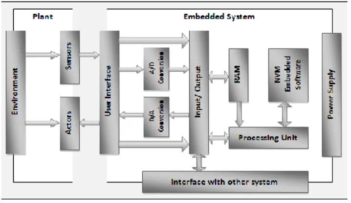
Figure 1 Scheme of an Embedded System
The embedded systems development platform is called a plant. The embedded software of the system is stored in some kind of non-volatile memory. Often this is ROM, but the software can also be in flash cards or on hard disk or CD-ROM, and downloaded via a network or satellite. The embedded software is developed for a particular target processor of that processing unit, which generally requires specific size of RAM to operate. As the ES processing unit can only process digital signals (ignoring analog computers for now) while the environment possible deals with analog signals, digital–analog conversions (two-way) take place (see Figure 1).
The processing unit handles all the input and output signals through a dedicated I/O layer. The embedded system interacts with the plant and possibly other (embedded) systems through specific interfaces. An embedded system designing includes main four steps [6].
The basic steps are the following: Requirements specification
Hardware and software partitioning Software design
Hardware design Interface design
System integration and test
System developers can derive required functions after evaluating system requirements. These functions are considered for allocation of hardware or software. Development of hardware and software is done parallel with the interface design. After development of all required hardware and software components, they are integrated to build a system and go ahead for the testing of system. The system level design steps are shown in Figure 2.
Figure 2 System-level design processes [4]
B. Model Driven Design
Model driven design (MDD) [3] is based on the efficient use of models as a primary objective throughout the software engineering life cycle. The main objective of MDD is to provide a central role to functional models in the specification, design, integration, and validation of software. Model driven development uses models to represent a system’s elements, the structural relationships between them and their dynamic interactions and behavior. Modeling structural relationship supports design exploration and system partitioning. The modeling behavior and interactions are required to verify designs by verifying models and for code generation. But many embedded software developers hesitate to accept the generated code. The rejection of code by developers means loss of MDD advantages. Use of the MDD approach means accepting automatic code generation from models.
A properly defined grammar and semantics models is capable of expressing both static structure and dynamic behavior. Such type of models at an abstract level differentiated from the programming domain must be articulated in a modeling language. These languages divided into two groups:
1) Vendor-specific language –It is developed and promoted by a specific vendor of an MDD platform such as Esterel from Esterel Technologies, MatLab and Simulink from MathWorks, and the ASD language used in Verum Software Technologies’ Analytical Software Design (ASD): Suite [3]. ASD Suite allows the system developer to create an initial set of requirements. There is no requirement of coding, testing, and refining each component in separate steps. In view of this, the modeling tool identifies both the external and internal performance of the elements using its two basic model types: interface models and design models.
2) Standardized languages – A group of interested industry
users and MDD platform vendors defined languages, which are most commonly based on the Unified Modeling Language (UML).
C. Test Driven Development
Test driven development (TDD) [3] provides various advantages over the traditional software development/test cycle. The test driven development using modeling provides the developer to create an initial set of requirements. In TDD, a developer finds out ways to build the system testable, designs as per the specifications, writes tests and builds, testing strategies, and then writes the functional code to meet the specified requirements of the test-spawned design. Advantages of TDD in embedded software:
1. The code is always tested. Testing drives the design of the code. The code is improved because of the decoupling required to create testable code.
2. The system grows organically as more knowledge of the system is gained. The tests are "living" documentation, because the knowledge is gained in tests.
3. The developers can alter existing code or add new features with confidence because automated regression testing will reveal failures and unexpected results. 4. Because of the inconsistency of hardware and software
during development, bugs are due to software, hardware, or a combination of the two.
Volume 5, Issue 6, June 2016
5. The software bugs can be removed to such an extent that it becomes easier to locate, by method of elimination, the cause of the unexpected system.
D. Overview of to fuzzy logic (FL)
In recent years, the number and variety of embedded system applications using fuzzy logic have much increased, such as washing machines, cameras, microwave ovens, medical instrumentation, decision-support system and industry process control. Fuzzy logic is an extension of the multivalued logical system. Fuzzy logic work is on a variable whose values are words rather than numbers, known as linguistic variable. Even though words are naturally less accurate than the numbers, their use is closer to human perception. Furthermore, computing with words exploits the tolerance for imprecision and thereby lowers the cost of solution [7]. Another basic concept that FL uses is fuzzy if-then rule. Although Artificial Intelligence (AI) is a rule based there is a lack-of mechanism dealing with fuzzy consequents and fuzzy antecedents. In FL, such mechanism is provided by the calculus of fuzzy rules, which serves as a basis for Fuzzy Dependency and Command Language (FDCL) [7].
E. Fuzzy Logic and Embedded Systems
Fuzzy logic can deal with the vague human concepts and natural language and distinguish its nature. Fuzzy algorithms are capable of understanding human concepts such as large, small, hot, cold, etc. It could also present a quite simple approach to derive definite conclusions from vague information. Almost all embedded system applications work on fuzzy logic [8]. The use of fuzzy logic in ES enhanced performance, increased productivity, reduced cost and time. Due to natural language processing, fuzzy logic has the advantage in modeling complex and nonlinear problems linguistically. However, the use of fuzzy logic requires expertise in understanding human knowledge to create algorithms that works like human thinking and expertise. The number of embedded applications uses the combination of fuzzy and neural networks. Neuro-fuzzy approaches take benefits of both fuzzy logic and neural network [9]. Some of the observations are:
Handle imprecise or vague information
Mimic the human decision-making process
Process numeric, linguistic, or logical information
Self-learn and self-organize
Learn by example and hence do not require the knowledge of a human expert
III. ANFIS BASED MODELING AND TESTING APPROACH The proposed plan of ANFIS based testing developed by using various components that play very important role in this approach. The modeling of embedded system is done through the Xilinx Integrated Software Environment, Simulink, Neuro-fuzzy logic controller, etc. Three distinct types of system models designed using a different mechanism and tested using ANFIS based testing approach for selection of suitable design. The testing early in the design phase reduces the cost and time required for the hardware design, software design, and verification and testing. The following sections describe the overview of the used components and
basic methodologies used for this research work.
A. Overview of Xilinx
The Xilinx Integrated Software Environment (ISE) is a design software suite [15] [16]. This allows you to take your design from design entry developed through Xilinx device programming. The Xilinx ISE Project Navigator (ISE PN) manages and processes system design through the following steps in the ISE design flow:
1. Design Entry
The first step in ISE design flow is design entry. As per the design objectives you can create your source files, using a Hardware Description Language (HDL), such as ABEL, Verilog, VHDL, or using a schematic. Lower-level source files can have multiple formats in your design.
2. Synthesis
In this step you have to run synthesis, which generate netlist files from the Verilog, VHDL, or mixed language designs that are provided to the next step.
3. Implementation
In this step, logical design converted to a physical file format by running implementation process from Project Navigator. These files can be downloaded to the specified target device. Execution of implementation processes depends on the target, such as a Complex Programmable Logic Device (CPLD) or a Field Programmable Gate Array (FPGA).
4. Verification
In this step, simulator software can be used to verify the functionality and timing of the design or its portion. To determine the correct circuit operation, the simulator compiles VHDL or Verilog code into circuit functionality and displays logical results of the described HDL. Simulation helps to create and verify complex functions in a very short time.
5. Device Configuration
After generating a programming file, device
configuration can be done. During this, you can generate configuration files and download the files from a host computer to a Xilinx device.
B. Overview of MATLAB Simulink
Simulink allows automatic code generation, simulation and continuous testing and verification of embedded systems. Simulink has a graphical editor, customizable block libraries, and solvers for modeling and simulating dynamic systems. Its integration with MATLAB, allows you to integrate MATLAB algorithms into models and also export results after the simulation to MATLAB for further analysis. According to MathWorks, Simulink coupled with their other products to automatically generate C source code for real-time implementation of systems. Due to Simulink flexibility and capacity for quick iteration it is widely used tool for embedded system designs and production systems. Simulink provides Embedded Coder (EC) to generate efficient code for embedded systems. It also allows verification and validation of models through requirement traceability, modeling style checking and model coverage analysis. Simulink Design Verifier (SDV) capable of identifying design errors such as division by zero, integer overflow and dead logic. It also generates test case scenarios
Volume 5, Issue 6, June 2016
for model checking within the environment. The Simulink tool TPT used to perform a formal verification and validation process to stimulate Simulink models. It is also used during the development phase where the developer generates inputs to test the system.
Some features of Simulink are:
Graphical editor for building and managing hierarchical block diagrams
Simulation engine with fixed-step and variable-step ODE solvers
Libraries of predefined blocks for modeling continuous-time and discrete-time systems
Model analysis tools for refining model architecture and increasing simulation speed
Scopes and data displays for viewing simulation results
MATLAB Function block for importing MATLAB
algorithms into models
Project and data management tools for managing
model files and data
Legacy Code Tool for importing C and C++ code into models.
C. Fuzzy Logic Controller (FLC)
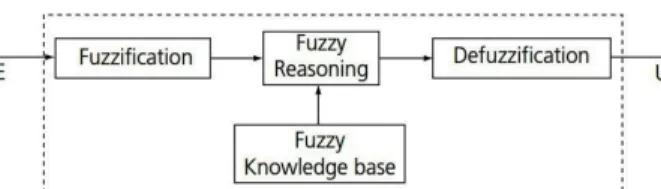
The basic structure of a fuzzy logic controller is depicts in Figure 3. The main components of fuzzy logic controller are a fuzzification unit, a fuzzy reasoning unit, a fuzzy knowledge base unit and a defuzzification unit. The process of converting inferred fuzzy control actions into crisp control action is known as defuzzificaton.
Figure 3 Basic structure of a Fuzzy Logic Controller A fuzzy input variable, E maps into a fuzzy output variable, U by the fuzzy knowledge-base which has a rule-base. A linguistic statement to express this is given as:
E → U (condition E implies condition U) which may be written as:
IF E THEN U.
There is an equivalence relation between obtained Cartesian multiplication relation and above expression is:
R = E × U ≡ IF E THEN U.
The fuzzy knowledge-base has a database defining the linguistic variables. A fuzzy membership function defines fuzzy set, which in turn defines the fuzzy variables. These variables constitute the fuzzy database. Fuzzy reasoning is used to deduce the output generated from each rule. The fuzzy outputs produced from each rule are collected and defuzzified to produce a crisp output.
D. Artificial Neural Network
The artificial neural network is based on a basic unit, called artificial neuron. A biological neural network is built using the nodes which simulate the action of a neuron. The links of
inputs x1, x2, x3 …, xn and output y to other nodes simulate synapses. Weights w1, w2, w3,…, wn are assigned to input links to simulate the action of the neurotransmitters. To produce the desired output, an algorithm is used to adjust the weights of the input links. This will simulate the process of learning. There are two types of learning modes: supervised and unsupervised. The supervised learning takes place with training sets of data, while unsupervised learning does not require any sample data. Unsupervised learning is adaptive or self-organizing. In biological systems unsupervised learning is very common. This type of learning is also important in artificial neural networks, as training data sets are not always available for the proposed application. The basic structure of artificial neuron is shown in figure 4 below. The output of the neuron can be expressed by:
Where, fh is a step function (known as the Heaviside function) defined by:
The θ is bias or offset with a permanent weight of 1, hence y will be given as:
The value of input x0 is always set to 1.
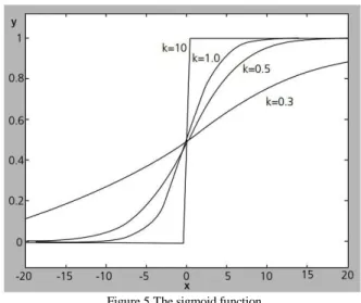
Using the Heaviside function leads to hard threshold [8]. In 1940’s the first neuron model was introduced by Warren McCulloch and Walter Pitts. The model is also called as the McCulloch-Pitts neuron or MP neuron. Other functions include the ramp and sigmoid functions with softer transitions are commonly used. The sigmoid function can be expressed as:
where, x is the total input, y is the output, and k is a gain factor that controls the sharpness of the transition from 1 to 0, as shown in Figure 5.
The sigmoid function is particularly useful because its derivative is easy to compute:
Volume 5, Issue 6, June 2016
Figure 5 The sigmoid function.
The Multilayer Perceptron – A multilayer perception is
used to overcome the difficulty of classifying linearly inseparable patterns. A nonlinear thresholding function, i.e. a sigmoid is also used. Layers of perceptrons with linear functions would not be more capable than a suitably chosen single layer. A typical architecture of a multilayer perceptron is shown in Figure 6.
Fuzzy Neuron (FN) - A possible model for a fuzzy neuron,
FN, which can express and process fuzzy information, was put forward by Kwan and Cai (see Figure 7). The fuzzy neuron has inputs xi associated with weights wi (i = 1 to n). It also has outputs yj (j = 1 to m); all of the outputs have values in the interval [0, 1]. These could represent membership values of a given pattern to a particular fuzzy set. The inputs may be thought of as the representation of a linguistic variable and the output expresses the membership values of assigned linguistic descriptions such as Tall, Medium, Small, etc. These values could then be propagated to other neurons [8].
Figure 6 A typical architecture of multilayer perceptron.
Figure 6 A typical structure of fuzzy neuron
Figure 6 A typical architecture of ANFIS
Figure 8 The proposed architecture of Neuro-fuzzy based testing of model driven embedded system
E. Adaptive Network based Fuzzy Inference System
A fusion of Neural Network and Fuzzy logic that work on Neuro-fuzzy technique, is known as Adaptive Neuro Fuzzy Inference System (ANFIS) [21][22][23]. The input and output parameters in ANFIS can be estimated such that both the Tsukamoto and Sugeno fuzzy models are represented by the ANFIS architecture [21]. This ANFS methodology is a combinational hybrid system of neural network and fuzzy logic technique. The typical architecture of ANFIS is shown in Figure 7. At first, the fuzzy logic work on its input variables that are derived with the help of the rules extracted from the input output data set of the modeled system. After this, the neural network is used to fine tune the rules to produce the final ANFIS model of the system.
F. Proposed ANFIS based Modeling and Testing Approach
The proposed architecture of ANFIS based testing of model driven embedded system is shown in Figure 8. The different models of one embedded system developed using different methodologies of model driven development. The inputs are supplied to these models at run-time through the input specification. The code generated and tested through the Neuro-fuzzy classification. The generated error verified and tested as per the required specification and test results are produced as an output.
G. Case Study:
To describe the proposed approach of testing, we consider the water flow controller in the field irrigation system. The water flow regulation in the field depends on the humidity and temperature.
1) Linguistic Variables
The structure of fuzzy system has logical inference flows from input variables output variables. The fuzzification of input variables is translated from analog values to desired
Volume 5, Issue 6, June 2016
one. Fuzzy inference rules are applied to the linguistic variables containing linguistics control rules. Output linguistics variable is goes through linguistic rules. The defuzzification of the output linguistic variable is translated into respective analog value.
a) The Input variables
The Table 2 shows the linguistic input variables, their type, unit, range, and default values.
Table 1: Linguistic variables
No. Input Variables
1. Humidity
2. Temperature
No. Output Variables
1 Pump-status
Table 2: Input linguistic variable details
No Linguistic Variable
Name
Type unit min max default Term name 1 Humidity Trimf (Triangular membership function) RH 0 100 0 Wet Medium Dry 2 Temperatu re Trimf (Triangular membership function.) Degree Celsius (0C) 0 100 0 Large-ne g Small-ne g Large
Table 3: Output linguistic variable details
No Linguistic
Variable Name
Type min max default Term name
1 Pump-status Constant 0 1 0 Close
Little open Half open Full open
b) The output variable
The Table 3 shows the linguistic output variable, its type, range, and default value.
2) Linguistic values
The real value of a linguistic variable is translated in linguistic values. The possible assumption of particular linguistic variable are identified and determined. Based on this linguistics values, the whole fuzzy logic works. The following table shows the determined linguistic value.
3) Membership function
Every linguistic variable is defined by its membership function. Given the membership function defined any value of input associated with degree of membership function. The following figure shows the membership function of input and output variables.
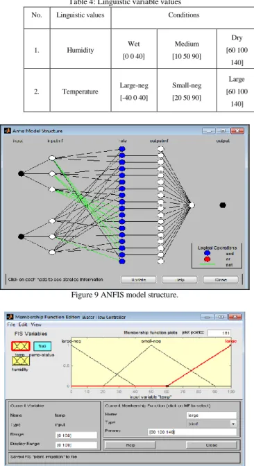
Adaptive Neuro Fuzzy Inference System (ANFIS) [11] model of the system containing input membership function, rule set and its output membership function with its output. Fuzzy Neural Network (FNN) structure of embedded system is shown in Figure 9. ANFIS adapts the weight based on the system environment [12]. Thus, the system becomes more intelligent and can predict future logic. The structure of fuzzy
system has logical inference flows from input variables to output variables. The fuzzification of input variables is translated from linguistic values to desired one. Fuzzy inference rules are applied to the linguistic variables containing linguistics control rules. The membership functions are shown in Figure 10(a), 10(b) and 10(c) of input and output linguistic variable humidity, temperature and pump-status respectively.
4) Development Models
The first model developed known as, Black box system, using Xilinx program code and is dumped in Simulink [19]. The code is generated using System Generator, and after execution of the code it generates the specified model for further testing using Neuro-fuzzy approach. The second model development is done using Adaptive Neuro Fuzzy Inference System (ANFIS) [20].
Table 4: Linguistic variable values
No. Linguistic values Conditions
1. Humidity Wet [0 0 40] Medium [10 50 90] Dry [60 100 140] 2. Temperature Large-neg [-40 0 40] Small-neg [20 50 90] Large [60 100 140]
Figure 9 ANFIS model structure.
Volume 5, Issue 6, June 2016
Figure 10(b) Membership function for input variable Humidity.
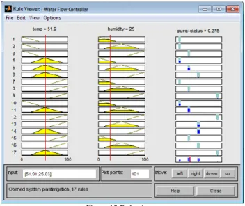
Figure 10(c) Membership function for output variable Pump-status. ANFIS applied first to the inputs and system generator block is used to create designs of the model system. After this VHDL code is generated and used in the process of test bench creation. This test bench is used for the process of Neuro-fuzzy testing. The third model is a design using a fuzzy logic controller, there is no ANFIS logic used, and complete logic is built by writing the required code for the system. The complete development is shown in the Figure 11. The Figure 12 is showing rule viewer for the proposed system.
Figure 11 Modeled Water Flow Controller systems
In Figure 13 the input/output variations for each model are shown. Here you can see that the model irrigation system showing pink line at 30, which should be 0 as it is shown in green colour. The graph for first model is showing consistency in the result of input and output variations. The second system is also shown better result in the graph, but the third model deviation in the result than the specified one.
Figure 12 Rule viewer 5) Verification and Testing of Models
The error graph generation helps in model based testing of embedded system. The Figure 14 illustrates the occurrence of graph for different models of same embedded system. As a result of this, developers can choose the better system. The model which provides less error will be selected as a good model and generate code for the hardware and software development of the specified system. In Figure 14, error graph for the first model (denoted by Error) shows the continuous changing its behaviour as per the variation in input and output. The error graph for a third model showing unexpected error output, while the error graph for second model showing constant result after variation in the input and output. Therefore, the second model design can be used as a good model design for the specified embedded system. The Neuro-fuzzy approach of testing embedded system model required implementation of the model in the real world with the necessary sensors and devices. More verification and testing required for the proposed model. This can be done through industry applications.
Figure 13 Input/output graphs of three models
Volume 5, Issue 6, June 2016
IV. CONCLUSION AND FUTURE WORK
Embedded systems have become an integral part of our day-to-day life. Medical instrumentation, bank machines, industry control systems, household machines and many more devices are now depends on the embedded system mechanism. The testing of embedded devices is becoming crucial day-by-day due to the increasing device complexities and safety and security requirements for human beings. As fuzzy logic and artificial neural networks playing an important role in the embedded devices, the ANFIS based modeling and testing of such systems is the necessity of the current era. This is the first step toward the development and testing of the model driven embedded system. Further work is required in this approach for the betterment of the model design and development process. We are working toward the testing of multiple embedded systems using the same approach. The heterogeneous designs of embedded system may be tested using the ANFIS based testing approach.
REFERENCES
[1] Pravin Karmore and Pradeep Butey, “Analysis of Model-based Testing Methodology for Embedded Systems”, International Journal of Advanced Research in Computer Science and Software Engineering, Vol. 6, Issue 5, pp. 308-314, May- 2016,.
[2] Hartman, Alan. “Model-Based Test Generation Tools”. http://www.agedis.de, 2011.
[3] Pravin Y. Karmore, Pradeep K. Butey, “Test Driven Development of Model Driven Embedded Systems”, International Journal of Science, Engineering and Technology Research (IJSETR), ISSN: 2278 – 7798, vol.5, Issue 6, pp. 1941-1945, June. 2016.
[4] Pravin Y. Karmore, Pradeep K. Butey, “Code Generation for Verified Model based Embedded Systems”, International Journal of Engineering Research & Technology (IJERT), ISSN: 2278-0181, Vol. 5 Issue 06, pp. 184-188, June-2016.
[5] Pravin Y. Karmore and Pradeep K. Butey, “Technical View of Testing Methodologies for Diverse Designs of Embedded System”, International Journal on Information Technology Management, vol. 2, ISSN2277 8659, 2013, pp. 123–131.
[6] Byeongdo Kang, Young-Jik Kwon, Roger Y. Lee, “A Design and Test Technique for Embedded Software”, Proceedings of the 2005 Third ACIS IEEE Int'l Conference on Software Engineering Research, Management and Applications (SERA’05), 2005.
[7] Aftab Ali Haider, Shahzad Rafiq, Aamer Nadeem, “Test Suite Optimization using Fuzzy Logic”, IEEE explore, 2012.
[8] Ahmad M. Ibrahim, “Fuzzy Logic for Embedded Systems Applications”, Elsevier Science (USA) e-book, 2004.
[9] W. Banks and G. Hayward, “Fuzzy Logic in Embedded Microcomputers and Control Systems”, Byte Craft Limited, Waterloo, Ontario, 2001. [10] T. A. Johansen, “Fuzzy Model Based Control: Stability, Robustness, and
Performance Issues,” IEEE Transactions on Fuzzy Systems, 2, 3, 221–234, 1994.
[11] Moataz A. Ahmed, Moshood Omolade Saliu, Jarallah AlGhamdi, “Adaptive fuzzy logic-based framework for software development effort prediction”, International Journal of Information and Software Technology, Volume 47, Issue 1, , pp. 31–48, January 2005.
[12] Ali Fuat Güneri, Tijen Ertay, Atakan Yücel, “An approach based on ANFIS input selection and modeling for supplier selection problem”, International Journal of Expert Systems with Applications, Volume 38, Issue 12, , pp. 14907–14917, December 2011.
[13] David Astels, “Test Driven Development: A Practical Guide”, Upper Saddle River, NJ: Prentice Hall PTR, 2003.
[14] Object Management Group. OMG Unified Modeling Language (OMG UML), Infrastructure, Version 2.4.1; August 2011.www.sysml.org. [15] ISE Simulator – In-depth Tutorial,
http://www.xilinx.com/support/documentation/sw_manuals/xilinx11/ug 682.pdf
[16] J. J. Blake, L. P. Maguine, T. M. McGinnity, L. J. McDaid, “Using Xilinx FPGAs to Implement Neurl Networks and Fuzzy Systems”, IEE, Savoy Place, London WC2R 0BL, UK, 1997.
[17] S. N. Sivanandam, S. Sumathi and S. N. Deepa, “Introduction to Fuzzy Logic using MATLAB”, ISBN-13 978-3-540-35780-3 Springer Berlin Heidelberg New York, 2007.
[18] Agam Kumar Tyagi, “Matlab and Simulink for Engineers”, Oxford publication.
[19] James B. Dabney, Thomas L. Harman, “Mastering Simulink”, Prentice Hall publication.
[20] Adriano Oliveira Cruz, “Adaptive Neuro-Fuzzy Inference Systems”, Mestrado NCE, IM, UFRJ, Logica Nebulosa–P. 1/33.
[21] J. S. R. Jang, “ANFIS: Adaptive-network-based fuzzy inference systems,” IEEE Trans. on Syst., Man and Cybern., vol. 23, no. 3, pp. 665–684, May/June 1993.
[22] J. S. R. Jang, C. T. Sun, and E. Mizutani, Neuro-Fuzzy and Soft Computing: A Computational Approach to Learning and Machine Intelligence. Prentice Hall Inc., 1997.
[23] J. S. R. Jang and C. T. Sun, “Neuro-fuzzy modeling and control,” Proc. IEEE, vol. 83, no. 3, pp. 378–406, March 1995.
Authors Profile
Dr. Padeep K. Butey obtained M.Sc. degree and
PGDCS&A from RTM Nagpur University, Nagpur. He obtained his Ph.D. degree in Computer Science from RTM Nagpur University, Nagpur. Now he is working as Associate Professor and Head at Dept. of Computer Science, Kamla Nehru College, Nagpur. He has published more than 35 research papers in various national and international conferences and journals. His research area includes RDBMS, Data Mining, Artificial Neural Networks and Fuzzy Logic.
Pravin Y. Karmore pursuing Ph.D. in Computer
Science from RTM Nagpur University, Nagpur. He is obtained Master in Computer Applications degree from RTM Nagpur University, Nagpur. And M.Phil. degree in Computer Science from Alagappa University, Karaikudi. At present he is working as Assistant Professor at Dept. of Computer Applications, Shri Ramdeobaba College of Engineering and Management, Nagpur. His research area is Software Engineering, Embedded Systems, Artificial Neural Networks and Fuzzy Logic.