Tribology in Industry
www.tribology.rsNumerical Study of Thermal Effect on the Friction
of Piston-cylinder Contact in an Internal
Combustion Engine
M. Belahcene
a, R. Mazouzi
a, M. Lounis
a,ba FIMA Laboratory, Faculty of Science and Technology, University of Djilali Bounaama Khemis Miliana, Khemis
Miliana, 44225, Algeria,
b LAAR, University of Science and technology of Oran, El M’Naouer 31000 Oran, Algeria.
Keywords: Friction Lubrication Piston-Liner
Thermohydrodynamic model Viscosity
A B S T R A C T
For the different operating regime of an internal combustion engine, the compartment ‘Piston-Ring-Liner’ represents the largest share of frictional power loss. This study presents a numerical analysis of ThermoHydroDynamic (THD) lubrication of an internal combustion engine piston to evaluate the thermal effect on the friction of piston-cylinder contact by considering three thermal models: isothermal, Global Thermal (GT) and THD. The results show that the choice of the thermal model has a great influence on the tribological characteristics of the piston-cylinder contact. The transition from the isothermal model to the THD model will lead to a decrease of approximately 6% of the minimum oil film thickness and an increase of 4% of the hydrodynamic pressure, and the transition from the GT model to the THD model will decrease 30% of the friction force in the piston-cylinder contact during an engine cycle.
© 2018 Published by Faculty of Engineering Corresponding author:
Maamar Belahcene FIMA Laboratory,
Faculty of Science and Technology, University of Djilali Bounaama Khemis Miliana, Khemis Miliana, 44225, Algeria.
E-mail: m.belahcene@univ-dbkm.dz
1. INTRODUCTION
Lubrication is essential in most of the mechanisms such as internal combustion engines. The lubricants must ensure the proper functioning of these mechanisms by inserting itself between the surfaces in relative motion. They ensure the mechanical behaviour, reduce the resistance due to friction and limit the wear of moving parts. Moreover, an optimized lubrication increases the efficiency by reducing mechanical losses due to friction. Fitzsimons [1] states that the frictional power loss for a typical IC engine is
15-20 % of all engine losses. This includes pumping losses as well. 40-50 % of these losses are due to piston-cylinder sub-system. Several research studies have been conducted on the lubrication of the piston-cylinder contact. The details of the skirt-liner interaction depend on various parameters. In order to determine the influence of these parameters, both experimental and numerical studies have been conducted on the lubrication of the piston skirt and on the secondary motion of the piston. Various numerical models are developed [2-3], including in some cases the role of the lubrication and the
R
ES
EA
R
elasticity of the skirt, without taking into account the thermal effects on the tribological characteristics of the contact. Gradually, some researchers recognized the importance of including thermal effects in hydrodynamic lubrication analysis. Two approaches have been proposed to account for the thermal effect in lubrication. These are the GT study and THD study. The first is to assess, from isothermal theory, the energy dissipated in the film, which is used to calculate an average operating temperature. The second is to simultaneously solve the energy equation and Reynolds equation that takes into account the variation of the viscosity through the film thickness.
The variation of lubricant viscosity with temperature is crucial insofar as it affects engine’s performance. Unfortunately, these effects are typically ignored in the models that are used to design engine components. Here the viscosity of the oil film is generally assumed to be constant over the cycle [2,4,5]. In recent years, to achieve the higher lubrication and cooling demands of engineering design, research on thermal effects has become meaningful and important because of its great influence on lubrication performance [6-9]. Richardson [10] carried out a theoretical investigation into the effects of viscosity variation and the effect of temperature gradient on lubrication. He concluded that temperature of the oil film is equivalent to the temperature of cylinder surface with the experimental results corresponding to the theoretical results. On this basis, other researchers have made tests with variable viscosity depending on the skirt surface temperature. Dowson et al. [11] and some other researchers [12,13] found that the steady-state THD condition includes three forms of thermal effects: viscous dissipation produced by the shear-rate within the oil film, conduction from or to the metal surfaces, and convection within the lubricant. In 2013, N. Morris [14] shows that the power loss due to viscous friction under isothermal condition throughout the engine cycle is actually larger than the losses of a thinner film with quite similar effective viscosity due to the small rise in lubricant temperature in the short contact transition time. Analyses are often idealised, such as isothermal condition and smooth surfaces, the former being particularly contrary to practice. An analytic solution to the average flow model is presented for this contact
with a new analytical thermal model. The generated contact temperatures, particularly at the inlet result in thinner films than the idealised analyses. In 2011, Syed and Malik [15] present a ThermoElastoHydroDynamic (TEHD) model which determines the effect of the variation of the lubricant viscosity and the piston displacement velocity on the tribological characteristics of piston-liner contacting. An increase in engine velocity reduces the transverse displacements of piston and minimizes the risk of a physical contact between the skirt and the liner. Thermal effects play an important role in the functioning of lubricated contacts.
In order to compare the different thermal approaches used in the tribological study of a piston-cylinder contact. A mathematical model of a piston skirt of mixed lubrication is presented. It considers the thermal effects on the tribological characteristics of contact as the hydrodynamic pressure, the oil film thickness and the frictional force. The hydrodynamic pressure field is calculated by the finite difference method. The resolution of the energy equation by the method of Gauss Siedel with relaxation used to determine the temperature field.
2. THEORY
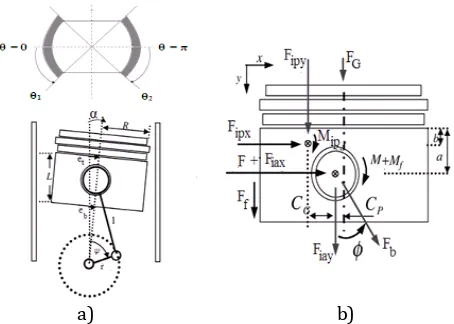
In Fig. 1a, the piston position and velocity are related to the crank angle ψ.
a) b)
Fig. 1. Piston/cylinder system. a) Field of piston lubrication, b) Forces and moments acting on the piston.
For a constant crankshaft speed, the piston position and velocity are given by [16,17]:
2 20.5 2 2 0.5
cos B
r Cp
r l
B = Cp + rsinψ (2)
2 2
0.5cos sin B l Br r U
(3)
The movement of the piston is defined by the resolution of the equations system below, considering the piston inertia, the hydrodynamic force, the friction force and the hydrodynamic moment. The equations of motion are derived based on the dynamic equilibrium of all the forces and moments applied to the piston. The system equation can be expressed as the following:
f S S b h p p p p a p a p M M M F F F e e L b b a m L I L b b a m L I L a m L b m L a m L b m tan ) ( 1 ) ( 1 1
(4)
with tg F F F
FS ( G Ia_y IP_y) (5)
g x IP P g
S F C F C
M _ (6)
The hydrodynamic pressure is governed by the Reynolds equation, which is written with the assumption of an incompressible thin film and a laminar flow [16,17]:
t h dy dh U y p h y x p h x h h 12 6 3 3
(7)
In our case the forces and moments, Fh and Mh are due to the hydrodynamic pressure developed in the oil film for the portions of surfaces limited by arcs (1,1) and (2,22). The pressure
condition in the non-lubricated areas is given by: phy,*0 1*2 (8)
In the border 0 and the pressure is maximum and it is expressed by a zero pressure gradient. 0 0
h h
p
p (9)
Symmetry condition of pressure in the film is given by:
ph(y,)ph(y,) (10) The pressure is zero at the top and the bottom of the skirt:
ph(0,)ph(L,)0 (11) The force and the hydrodynamic moment fh, mh due to the hydrodynamic pressure ph of oil film are determined by the integration of the
hydrodynamic pressure on the lubricated area [2,16]:
0 0 cos 2 L hh R P d dy
F (12)
The hydrodynamic moment is given by:
dy d y a P R M L h
h
cos ) ( 2 0 0
(13)The hydrodynamic friction force and its moment about the wrist pin may be calculated from the shear stress:
0 0 2
L
fh R d dy
F (14)
dy d C R R M p L
fh
) cos ( 2 0 0
(15)For the contact pressure, we used the approximate solution given by Zhu [2] for an aluminum piston: 0552 . 1 13 10 464 .
5
c
P (16)
with δ is the deformation of the wall.
The total contact force acting on the piston skirt and its moment about the wrist pin may be calculated by:
0 0 cos 2 L cc R P d dy
F (17)
dy d y a P R M L c
c
cos ) ( 2 0 0
(18)The force and the moment of contact friction of the asperities in a potential solid-solid contact between the piston skirt and the cylinder bore are calculated by the following equations:
0 0 2 L c ffc Pd dy
U U R c
F (19)
0 0 cos 2 L p c ffc P R C d dy
U U R c
M (20)
f
c is the coefficient of solid friction, it is
determined experimentally [16].
The oil film being secured to the piston in its movement, its thickness will be closely linked to the secondary piston movement, neglecting the elastic deformation, the lubricant film thickness is given by:
) cos( )) ( ) ( ( ) cos( ) ( ) , , ( L y t e t e t e c t y
2.1. Equation of the viscosity with temperature
In the isothermal study, lubricant viscosity is
constant throughout the procedure
hydrodynamic calculation. To determine the lubricant viscosity in the engine cycle of the GT and THD study, we used the Vogel equation [18] which is most suited in the case studied:
𝝁(𝑻) = 𝝆𝒂𝟎𝐞𝐱𝐩[𝑪+𝑻𝑩 ] (22)
where a0, B and C are Vogel correlation parameters. For SAE-20 oil, ρ= 832 kg/m3, a0=0.058 cst, B=1028 °C and C=108 °C.
2.2. Temperature equations
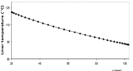
In the GT study, the oil temperature varies slightly between the top and bottom of the piston skirt, and it varies quite substantially between the position of Top Dead Centre (TDC) and the position of Bottom Dead Centre (BDC) on the liner. To set this variation, we use the Woschni correlation [19].
S x ) T (T T
T(x) TDC TDC BDC
(23)
where T(x) is the liner temperature, presumed to be the same as the lubricant temperature [20, 21], x is the liner location (measured downward from TDC), TTDC and TBDCare the temperatures at the TDC and BDC. The temperature profile is shown in Fig. 2.
Fig. 2. Liner temperature as a function of distance on the liner from the TDC.
According to the mechanics theory of viscous thin films and taking into account that the film thickness is very small compared to its extent, the simplified energy equation [22] is given by:
2 2 2 2 2 1 T R y T K y T U
cp c (24)
where is the viscous dissipation, it is expressed by:
y P U h U h 2 2 2
(25)
The energy equation is discretized by the finite difference method and solved by Gauss Siedel method with relaxation coefficient. This resolution allows obtaining the temperature field in the oil film. The boundary conditions used to solving the energy equation are:
0 0 0 y T L y T T y (26) and 0
T for 0 and (27)
The discretization of the energy equation by the finite difference method gives as:
y P U h U T R K T R K T y K T y U c R K y K T y K y U c h j i c j i c j i c j i p c c j i c p 2 2 2 2 2 1 , 2 2 1 , 2 2 , 1 2 , 2 2 2 , 1 2
2.3. Resolution method
In order to approximate the lubricating pressure field, we employ the finite difference method with a uniform grid, rectangular mesh elements is used for the film, with m elements in the axial direction (y) and n elements in the circumferential direction (θ). Only the area where there is the lubricant film is considered. The symmetrical nature of the piston in the circumferential direction was adopted (Fig. 3). Equation (4) and equation (7) are nonlinear in
P, et and eb, and are solved by the iterative Newton-Raphson method after discretization by finite differences.
Wx, Wy and E are the respective residues of equations (4) and (7) obtained for the et, eb and
P solutions of the system at the step s. The corrections to the step s+1 are obtained after solving the linear system.
0 ) 1 ( ) ( ) (
s
This can be written in matrix form:
R + [J] Δ=0
where [J] is the jacobian matrix of the hydrodynamic problem. With a time step that corresponds to 5 degrees of crankshaft angle, convergence is reached after four to five engine cycles.
Fig. 3. Mesh of developed lubricant film.
Fig. 4. Flowchart resolution.
For obtain the temperature field in the oil film, we use the Gauss Sidel method with relaxation.
, 1 4
1 1 , 3 , 1 2 1 , 1 1 1 ,
, 1 T CT C T C(T T ) C
T ij n
n j i n j i n j i n j i n j
i
With Ω is relaxation coefficient equal to 1.3-1.9
y U c R K y K y U c y K C p c c p c 2 2 2 2 1 2 2
y U c R K y K y K C p c c c 2 2 2 2 2 2 2 y U c R K y K R K C p c c c 2 2 2 2 2 3 2 2
y U c R K y K C p c c 2 2 2 4 2 2
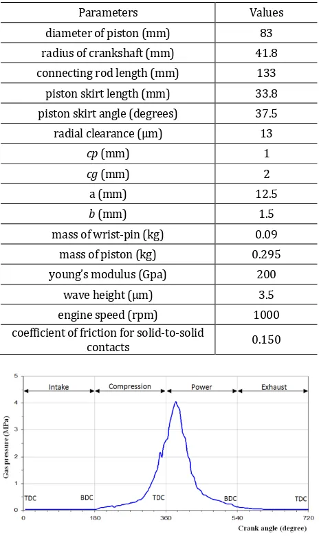
The calculation procedure is presented in fig. 4. At each time step (or crankshaft angle), the Reynolds equation (7) and the equations of piston motion (4) are resolved. We start by introducing all geometry and simulation data of this mechanism as shown in table 1 and all values of combustion gas pressure which presented in Fig. 5.
Table 1. Geometry and simulation data.
Parameters Values
diameter of piston (mm) 83
radius of crankshaft (mm) 41.8
connecting rod length (mm) 133
piston skirt length (mm) 33.8
piston skirt angle (degrees) 37.5
radial clearance (μm) 13
cp (mm) 1
cg (mm) 2
a (mm) 12.5
b (mm) 1.5
mass of wrist-pin (kg) 0.09
mass of piston (kg) 0.295
young’s modulus (Gpa) 200
wave height (μm) 3.5
engine speed (rpm) 1000
coefficient of friction for solid-to-solid
contacts 0.150
Fig. 5. Variation of combustion gas pressure with crank angle.
rest of cycle. Once the oil film thickness h is calculated as given in equation (21), Reynolds equation (7) is resolved using a new value of Ph based on the available values of eh, eb, etand
e
b.After, we calculate all forces and moments which are located on the right side of equation (4). If residues of equations (4) and (7) less than 10-5,
the convergence criterion is satisfied for Ph, et and eb and we pass to the next time step. The temperature field is calculated by equation (24). The convergence criterion is satisfied for T when
δT/T<10-7at each successive time step for the all engine cycle. After that, the oil viscosity is calculated after the determination of lubricant temperature as written in equation (22). Execution with one time step which corresponding to 5 degrees of crankshaft angle, requires 20 to 80 iterations for the solution convergence. For a four-stroke engine, with two towers of crankshaft (720 degree crankshaft angle) for each cycle, it is noted that during the execution test, convergence of the periodic solution is obtained from 3 to 4 engine cycles.
3. RESULTS
The results presented in this section focus on the tribological characteristics of the contact (viscosity, temperature, film thickness ...). The different operation models of the contact between the piston skirt and cylinder (isothermal, GT and THD) has been considered.
The Fig. 6 shows the temperature variation as function of crank angle in the engine cycle. It is observed that, the temperature ranges from 89 °C to 115 °C during the engine cycle. In the THD model, the variation is of around1 °C, from 93 °C to 94 °C. This difference is explained by the model used, in the GT model, the average temperature of the lubricant is determined from the temperature of the solid (liner) shown in Fig. 2, which varies between the TDC and the BDC positions but, in the THD model, these values are obtained from the numerical solution of the energy equation which is defined by the boundary and initial conditions of real model of heat transfer in the piston operation. The temperature changes affect directly the lubricant viscosity as shown in Fig. 7. In the isothermal model, the values of viscosity are constant during the engine cycle with a value that is 0,016 Pa.s. In the THD model, oil viscosity varies
slightly because of the temperature stability against in the GT model, we can see the wide variation in viscosity caused by the large change of the lubricant temperature.
Fig. 6. Variation of lubricant temperature with crank angle.
Fig. 7. Variation of dynamic viscosity during the engine cycle.
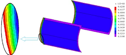
The Fig. 8 shows the temperature distribution in the oil film at crank angle ψ = 285° of the THD model. In this figure, the temperature is uniform and equal to 48 °C over the entire film, except for an increase of temperature at the top side of the skirt caused by a heat transfer by convection in right side of the combustion chamber from 59 to 150 °C. However, at the bottom of the piston, the temperature is about 37 °C.
Fig. 8. Temperature distribution in oil film at ψ = 285°.
Fig. 9. Hydrodynamic pressure distribution in oil film at ψ = 395°.
We note that, the hydrodynamic pressure profile is different in the three models. The maximum pressure is 6.3 MPa, this pressure is located at the maximum thrust side THD model. A pressure field is practically zero at the minimum thrust side in isothermal and TG models. However, a moderate hydrodynamic pressure is observed at the minimum thrust side. The extent of this pressure is wider in the in the Isothermal and GT than in the THD model. Table 2 shows a comparison of results obtained with a rigid skirt in the different lubrication models especially, the maximum hydrodynamic pressure, the minimum oil film thickness and the average contact friction force in an engine cycle. It is found that, the values of tribological contact parameters are variable with the variation of the study models isothermal, GT and THD of piston lubrication. Comparing the results obtained with the three models, a slight increase of the maximum hydrodynamic pressure through the engine cycle is observed in the THD case with respect to the isothermal model. The increase would be around 4 %. The transition from the isothermal model to the THD model will lead to a decrease of 6 % of the minimum oil film thickness in all engine cycle and the passage of a GT model to THD model will decrease 30 % of the average contact friction force in an engine cycle. The THD analysis provides the tribological characteristics of the contact and gets including better fuel efficiency by reducing the contact friction.
Table 2. Tribological characteristics of piston -cylinder contact.
characteristics isothermal GT THD
Ph(MPa) at 395° 5.897 5.878 6.146
hmin(µm) at 430° 3.319 3.146 3.127
Ffc (N) average value 4.18 21.73 15.05
Fig 10. Variation of the minimum oil film thickness with crank angle.
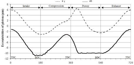
The Fig. 10 shows the minimum oil film thickness as a function of the crank angle. Over the cycle, the oil film thickness increases in the middle of each race and the skirt-liner contact is predicted to operate in the hydrodynamic regime of lubrication with the exception in the power stroke in the three models, where the lubrication regime remains mixed during the power stroke. However, this film thickness falls during the intake phase and then increases during the compression phase in the GT and the THD model. This film thickness is 3 µm throughout the expansion process. Generally in the isotherm case the regime of lubrication remains hydrodynamic because of the higher lubricant viscosity at a lower liner temperature. Trajectories of the upper and lower side of the piston are shown in Fig. 11, where the positive sign means a shift to the minimum thrust side. The lateral displacement of piston is limited by the radial clearance (13 μm). It is noted that, bottom of the piston skirt is closer to the cylinder wall on the maximum thrust side during the power stroke and at the end of admission stroke.
Fig. 11. Piston secondary motion.
region. The position of maximum friction differs according to the liner working temperature, which also affects the film thickness and the lubricant viscosity.
Fig. 12. Contact friction force in an engine cycle of the three models isothermal, GT and THD.
The Fig. 13 shows that the contact friction force of the GT model is higher than other models. This can be explained that during the power stroke, the minimum film thickness of this model is lower to other models as shown in Fig. 10. Hydrodynamic friction forces in an engine cycle are shown in Fig. 14.
Fig. 13.Average contact friction force in an engine cycle of the three models isothermal, GT and THD.
Fig. 14. Hydrodynamic friction force in an engine cycle of the three models isothermal, GT and THD.
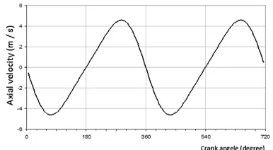
It note that, the hydrodynamic friction force reached a maximum value in the middle of each race because of the elevation of the piston sliding speed shown in Fig. 15 for the engine speeds of 1000 rpm, which generates a high shear rate in the oil film and therefore a high hydrodynamic friction force, against it vanishes with the change of piston displacement direction with zero speed at TDC and BDC. Throughout the engine cycle, the hydrodynamic friction force is higher in the GT and THD models comparing with the isothermal model as can be seen in Fig. 16 due to the lubricant viscosity that shown in Fig. 7, which is generally higher in the model GT compared to isotherm and THD models throughout the engine cycle.
Fig. 15. Axial velocity of the piston as a function of crank anglefor the engine speeds of 1000 rpm.
Fig. 16. Average hydrodynamic friction forces in an engine cycle of the three models isothermal, GT and THD.
The average total friction force in an engine cycle is shown in Fig. 17.
Throughout the engine cycle, the total friction forces of the THD and GT models are higher than the isothermal model. The transition from the THD model to the GT model will lead to an increase of 6 % of the average total friction force in an engine cycle. The explanation for this increase directly related to the viscosity of the lubricant film. A low oil viscosity can reduce the hydrodynamic friction forces in THD model.
4. CONCLUSION
This analysis shows that thermal effects should be included in the study of piston-cylinder contact. The surface temperatures of the solids contact are influenced by the combustion gasses and heat by viscous shear of the lubricant film and more by the heat generated through contact friction. Therefore, a realistic model should encompass boundary interactions. The results confirm a viscous shear of the lubricant film under thermal mixed hydrodynamic regime of lubrication. Three thermal models are presented to evaluate the thermal effects on the piston-cylinder contact. The analysis shows that the transition from the Isothermal model to the THD model will lead to a decrease in the minimum oil film thickness and an increase in the hydrodynamic pressure, and the transition from the GT model to the THD model will decrease 30 % of the contact friction force in the contact. Three thermal models are presented to evaluate the thermal effects on the piston-cylinder contact. The comparison of the three models presented in this work can be used to evaluate the contact friction of piston for improve the efficiency of the internal combustion engine.
Abbreviation
BDC Bottom Dead Centre GT Global Thermal
TEHD ThermoElastoHydroDynamic THD ThermoHydroDynamic TDC Top Dead Centre
REFERENCES
[1] B. Fitzsimons, Introduction to the importance of fuel efficiency and role of the Encyclopaedic research
project, In IMechE seminar: a drive for fuel efficiency, Loughborough, UK, September, 2011. [2] D. Zhu, H.S. Cheng, Y.Z. Hu, T. Arai, K. Hamai,A
numerical analysis for piston skirt in mixed lubrication, part ii: deformation considerations, ASME Journal of Tribology, vol. 115, iss. 1, pp. 125–133, 1993, doi: 10.1115/1.2920965
[3] V.W. Wong, T. Tian, H. Lang, P. Ryan, Y. Sekia, Y. Kobayashi, S. Aoyama, A numerical model of piston secondary motion and piston slap in partially flooded elastohydrodynamic skirt lubrication, in Annual congress and exposition, Detroit, MI, SAE paper 940696, 1994, doi: doi.org/10.4271/940696
[4] K. Liu, Y.B. Xie, C.L. Gui,A comprehensive study of the friction and dynamic motion of the piston as-sembly, Proceedings of the Institution of Mechanical Engineers, Part J: Journal of Engineering Tribology, vol. 212, no. 3, pp. 221-226, 1998, doi: 10.1243/1350650981542038
[5] S. Balakrishnan, H. Rahnejat, Isothermal transient analysis of piston skirt-to- cylinder wall contacts under combined axial, lateral and tilting motion, Journal of Physics D: Applied Physics, vol. 38, no. 5, pp. 787-799, 2005.
[6] F.M. Meng, Y.Y. Zhang, Y.Z. Hu, H. Wang, Thermo-elasto-hydrodynamic lubrication analysis of piston skirt considering oil film inertia effect, Tribology International, vol. 40, iss. 7, pp. 1089-1099, 2007, doi: 10.1016/j.triboint.2006.10.006
[7] R. A.J. van Ostayen, A. van Beek, Thermal modelling of the lemon-bore hydrodynamic bearing, Tribology International, vol. 42, iss. 1, pp. 23–32, 2009, doi: 10.1016/j.triboint.2008.05.013
[8] M.A. Ahmad, S. Kasolang, R.S. Dwyer-Joyce, Experimental study on the effects of oil groove location on temperature and pressure profiles in journal bearing lubrication, Tribology International, vol. 74, pp. 79–86, 2014, doi: 10.1016/j.triboint.2014.02.012
[9] J. Durany, J. Pereira-Pérez, F. Varas, Some aspects of lubrication in heavy regimes: Thermal effects, stability and turbulence, Mathematics and Computers in Simulation, vol. 102, pp. 90– 103, 2014, doi: 10.1016/j.matcom.2013.09.005
[10] D.E. Richardson, G.L. Borman, Theoretical and experimental investigations of oil films for application to piston ring lubrication, SAE Technical Paper, No. SAE-922341, 1992, doi: 10.4271/922341
Engineers, Conference Proceedings, vol. 181, no.
2, pp. 70–80, 1966, doi:
10.1243/PIME_CONF_1966_181_034_02
[12] K.W. Kim, M. Tanaka, Y. Hori, A three dimensional analysis of thermohydrodynamic performance of sector-shaped, tilting-pad thrust bearings, Journal of Lubrication Technology, vol. 105, iss. 3, pp. 406-412, 1983, doi: 10.1115/1.3254625
[13] T. Han, R.S. Paranjpe, Finite volume analysis of the thermohydrodynamic performance of finite journal bearings, Journal of Tribology, vol. 112, iss. 3, pp. 557–565, 1990, doi: 10.1115/1.2920293
[14] N. Morris, R. Rahmani, H. Rahnejat, P.D. King, B. Fitzsimons, Tribology of piston compression ring conjunction under transient thermal mixed regime of lubrication, Tribology international, vol. 59, pp. 248–258, 2013, doi: 10.1016/j.triboint.2012.09.002
[15] Q. Syed Adnan, M. Afzaal Malik, A. k. Mumtaz, Riaz A. Mufti, Low viscosity shear heating in piston skirts ehl in the low initial engine start up speeds, Tribology international, vol. 44, iss. 10,
pp. 1134–1143, 2011, doi:
10.1016/j.triboint.2011.04.018
[16] D. Zhu, H. S. Cheng, T. Arai, K. Hamai, A numerical analysis for piston skirt in mixed lubrication- part i: Basic Modelling, ASME Journal of Tribology, vol. 114, iss. 3, pp. 553-562, 1992, doi: 10.1115/1.2920917
[17] R. Mazouzi, P. Maspeyrot, A. Kellaci, D.D. Rahal, Effet des parametres de conception du piston sur le frottement jupe-chemise, Mécanique & Industries, vol. 10, iss. 2, pp. 91-101, 2009, doi: 10.1051/meca/2009037
[18] A. Cameron, Basic lubrication theory, Third edition. Ellis Horwood LTD., 1983.
[19] G. Woschni, K. Zeilinger, Vorausberechnung des Kolbenringverhaltens, in FVV Workshop, Tribosystem Kolben – Kolbenring -Zylinderlaufflaeche, 10. Okt. 1989, VDMA-Haus Frankfurt.
[20] Z. Ma, N.A. Henein, W. Bryzik, A model for wear and friction in cylinder liners and piston rings, Tribology Transactions, vol. 49, iss. 3, pp. 315-327, 2006, doi: 10.1080/05698190600678630
[21] R. Rahmani, H. Rahnejat, B. Fitzsimons, D. Dowson, The effect of cylinder liner operating temperature on frictional loss and engine emissions in piston ring conjunction, Applied Energy, vol. 191, pp. 568-581, 2017, doi: 10.1016/j.apenergy.2017.01.098
[22] F.P. Incropera, D.P. Dewitt, Fundamentals of heat and mass transfer, 5th edition, New York: Wiley,
2002.
NOMENCLATURE
a : Vertical distance from the top of piston skirt to the wrist-pin (m)
b : Vertical distance from the top of piston skirt to the piston center of gravity (m) c : Radial clearance between the piston and
the cylinder (m)
Cf : Boundary friction coefficient
Cp : Distance of the wrist-pin from the axis of
piston (wrist pin offset) (m) cp : Specific heat oil (j.k-1)
t
e ,eb : Eccentricities of piston at the top and bottom of the skirt respectively (m) F : Total normal force acting on the skirts of
both sides (N)
Fb :Connecting rod force (N)
Fc :Normal force due to solid-to-solid contacts (N)
Fgaz : Combustion gas force acting on the top of
piston (N)
Ff : Total friction force acting on the surfaces of
skirts (N)
Ffc :Friction force due to solid-to-solid contacts
(N)
Ffh :Friction force due to hydrodynamic
lubricant film (N)
Fh :Normal force due to hydrodynamic
pressure in the film (N)
Fia_x, Fia_y: Inertia forces due to wrist-pin mass (N)
Fip_x, Fip-y :Inertia forces due to piston mass (N)
h : Lubricant film thickness, (m)
p
I :Piston rotary inertia about its center of mass (kg.m2)
Kc : Thermal conductivity (w.m-1.k-1)
L : Piston skirt length (m) l : Connecting rod length (m)
M :Total moment about wrist-pin due to all the normal forces (N.m)
Mf :Moment about wrist-pin due to all the
a
m :Wrist-pin mass (kg)
p
m :Piston mass (kg)
Pc :Solid-solid contact pressure (Pa)
Ph :Hydrodynamic pressure (Pa)
R :Radius of piston (m) r :Crank radius (m)
T :Lubricant temperature (k)
TTDC, TBDC :Temperatures at the top and bottom dead
centre respectively (k) t :Time (s)
U :Piston sliding velocity (m.s-1)
x :Position on the cylinder measured from the top dead center (m)
Y :Axial position of the piston (m) y :Coordinate originated from the top of
skirt (m)
δ :Solid-solid contact deformation (m) θ :Angular coordinate (rd)
:Lubricant viscosity (Pa.s) ρ :Lubricant density (kg.m-3)