_____________________________________________________________________________________________________
Computational Fluid Dynamics (CFD) Modelling of
Mixture Formation in Gasoline Direct Injection (GDI)
Engine
Sherry Kwabla Amedorme
1*and Joseph Apodi
21Department of Mechanical and Automotive Technology, University of Education,
Winneba –Kumasi, Ghana.
2
Bolgatanga Polytechnic, P.O.Box 767, Bolgatanga, Upper East Region, Ghana.
Authors’ contributions
This work was carried out in collaboration between both authors. Both authors read and approved the final manuscript.
Article Information
DOI: 10.9734/JERR/2019/v7i216968 Editor(s): (1) Dr. Guang Yih Sheu,Associate Professor,Chang-Jung Christian University, Taiwan. Reviewers: (1) Asad Ullah, Kohat University of Science and Technology,Pakistan. (2) J Dario Aristizabal-Ochoa, Universidad Nacional de Colombia, Colombia. (3) P.A. Murad, LLC, USA. Complete Peer review History: https://sdiarticle4.com/review-history/51237
Received 29 June 2019 Accepted 04 September 2019 Published 28 September 2019
ABSTRACT
Automotive engine faces stringent regulations on emission with improved fuel consumption. As such, the Gasoline Direct Injection (GDI) engines which have the potential to meet these requirements are being improved on especially the mixture formation to the burning of the mixture. In GDI, late injection compared with early injection scheme generates charge stratification which contributes to the optimised fuel consumption and combustion. As a result, this strategy in GDI engines is considered to be promising with increasing research focus. This paper aims at evaluating the computational fluids dynamics (CFD) modelling of two-phase transient injection process in generic GDI engines with the late injection to study the features of fuel atomisation process, injection velocity and its influence on turbulence. The commercial CFD code Star CCM+ was used to perform this simulation due to its advanced polyhedral mesh technology and the user-friendly interface. Transient liquid and gas flow inside the combustion chamber was simulated using the Eulerian multiphase segregated flow model with k-epsilon turbulence. The contour plots show that during the injection period turbulence for each phase was independent of the spray
shape predicted to be asymmetric under non-vaporisation conditions. In addition, increasing injection velocity of liquid fuel causes stronger turbulence for the liquid phase. The results also show that the variation of turbulence for gas-phase is mainly centred in the region of the inlet during the injection process and non-homogenous turbulent characteristics were observed for the late injection with the volume fraction of the liquid phase also seen to be asymmetric.
Keywords: GDI engines; CFD; two-phase flow; turbulence; liquid atomisation; mixture formation.
1. INTRODUCTION
Gasoline Direct Injection (GDI) is regarded as a wide-used technology in modern spark ignition (SI) engines due to its improved thermal efficiency and exhaust emission compared with port fuel injection [1-4]. Generally, there are two types of GDI engines with different injection strategies, early injection operating under homogeneous charge mode while late injection at stratified charge condition. It is indicated that the latter could achieve the potential of GDI engine on better fuel economy and emission level [4,5]. As a result, the GDI engine with late injection and its process of mixture formation and fuel atomisation leading to fuel vaporisation and burning of the air-fuel mixture has been a research focus.
In the GDI engine, fuel is injected directly into the combustion chamber where air-fuel mixture forms simultaneously which seems to solve mixture control problem occurring in Port Fuel Injection (PFI) engines fuel efficiency [3]. It applies charge stratification at part load to premix the fuels with air in the combustion chamber during the late period of the compression stroke. In this case, the ratio of air to fuel is stoichiometric near the spark plug while close to cylinder walls it is leaner with the tendency to reduce engine knock. Hence, the lean air-fuel mixture possibly gives rise to improved fuel economy.
Additionally, due to stratified charge, the progressive charge cooling is realised which contributes to the utilisation of higher compression ratio without the risk of engine knock. Under such circumstances, the thermal efficiency is significantly increased [6].
Furthermore, because of this lean combustion and the position the injector, the mixture control may not depend on throttling and there is an indication that pumping loss due to cycle work could be reduced compared with traditional PFI engine [2,7,8].
In spite of the increased power output produced by GDI engine at part load operation, recent research reveals thatthis lean mixture formation in combustion chamber could lead to misfires and emissions of unburned hydrocarbon to some extent which possibly weakens the advantage of this engine compared with PFI engine. Hence, in order to mitigate the effect of potential drawbacks of lean mixture formation in the GDI engine with late injection, the quality of mixture formation in this engine should be improved [9,10].
In GDI engines with late injection, the time for fuel to mix with air is limited. In order to obtain a desirable proportion of mixture, strong turbulence produced by tumble motion or swirl motion must be improved. The turbulence inside the cylinder is dependent on the injection geometry and this injection parameter appears to be sensitive to the type of injector [11,12]. Therefore, the utilisation of proper injectors plays an import part in enhancing the performance of mixture formation which in turn, mitigates the emission degree and further improves the fuel economy for GDI engine with late injection [13]. Swirl injector and multi-hole injector are widely employed, and a recent study reveals that the latter shows a significant promise in acquiring a better quality of mixture formation compared with the former [14].
The position of the spark plug in GDI is central at the combustion chamber while the injector position can be varied. In terms of the width of the gap between spark plug and injector, there are mainly two arrangements for the position of injector, namely, narrow spacing and wide spacing [15].
while the methods to obtain charge stratification are distinguished. These features are spray-guided, wall-guided and air-guided [15,16].
For the spray-guided system, the injector is conventionally located close to the centre of the combustion chamber and the stratification process is strongly dependent on characteristics of spray dynamics whilst wall-guided system employs a cavity on the top of the piston to interact with spray to achieve stratification [17]. Another feature of this layout is that the injection is set proximate to the centrally fixed spark plug without cavity surface piston being arranged in the cylinder. In the air guided systems, stratification is obtained mainly by means of the interaction between the fuel spray and the motion of the air charge inducted in the cylinder [3].
The atomization process is also important to the spray formation which is the process where liquid fuel is broken up into drops and is of significance for liquid fuel to effectively burn in combustion chamber [13,18]. It is observed that the atomisation of liquid fuel is conventionally carried out by atomisers which is probably a part of injector on the scope of the internal combustion engine, and one of the acceptable classifications
of atomiser is based on the energy that is applied for the purpose of atomisation[19].
It is also established that the swirl atomiser could provide strong tumble or swirl for GDI engine with the late injection to achieve the anticipated charge stratification for mixture formation. Jet atomiser helps to study the process of disintegration of liquid into drops which usually takes place at a certain distance away from the atomiser. The degree of disintegration is determined by many factors such as the dimension of orifice, discharge velocity and ambient conditions. Typically, increasing the velocity of discharge may accelerate this process of break-up [13,19,20].
2. EULERIAN MULTIPHASE MODEL
In STAR CCM+, Eulerian multiphase segregated flow tends to meet the requirements of two-phase flow inside a GDI combustion chamber. The important governing equations for Eulerian multiphase segregated model are the conservation laws for mass, momentum and energy equation which is not originally included in Eulerian multiphase (EMP) model but provided in Star CCM+ as segregated fluid isothermal [21].
Mass conservation (Continuity)
V i cd V j i ji ij A g i i i V ii dV v v da m m a dV S dV
t 0 ( ) 0 ( ) 0
(1)
Momentum conservation dV a v m v m dV S dV a F dV a M da gdV pdV da dV t cd V i ji j ij V i cd V V cd i A t i i i V i i V A V i g i i i i i
0 0 i 0 int 0 0 0 0 ) ( ) ( )] ( [ (2) Energy conservation ) ( ) ( ) ( ) ( )]) ( [ ) (( , ) ( ij i j i ji ij i u ij ij i j i ij i i i i i i eff i g i g i i i i i i i t h m m S Q Q v f v T t k p v v v H E t
, (3)For the above equations where:
i
: The volume fraction for phase i and 1i i
i
: The density for phase i
: The void fractioni
v
: The velocity for phase ig
v
: The grid velocityij
m
: The mass transfer rate from phase j to iji
m
: The mass transfer rate from phase i to jcd
a
: The density in the interaction area
i
S
: The mass source term for phase ip
: The pressure (equal for each phase)g
: The gravity vectori
: The molecular stresst i
: The turbulent stressi
M
: The interphase momentum transfer per unit volume and
iM
i
1
i
F
)
(
int : The internal force
i
S
: The momentum source term for phase ii
E
: The total energy for phase ii
H
: The total enthalpy for phase ii
T
: The viscous stress tensor for phase ii
t
: The temperature for phase ii eff
k
, : The effective thermal conductivityi
f
: The body force vector for phase iij
Q
: The interphase heat transfer rate from phase j to i) (ij i
Q
: The heat transfer rate from phase pair interface (ij) to phase ii u
S
, : The energy source)
(
ij it
h
: The enthalpy estimated at the interface temperaturet
ijfor phase i3. NUMERICAL PROCEDURE
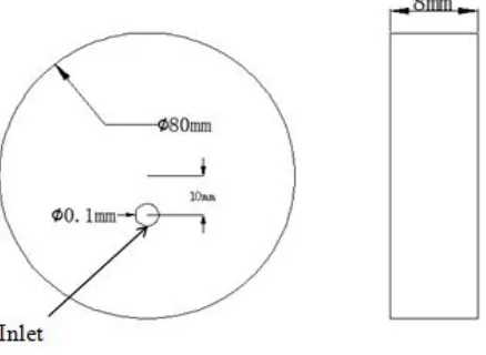
The computational domain for simulations is the combustion chamber of the GDI engine and the piston is near the top dead centre (TDC) on the compression stroke and the fuel is sprayed representing the late injection strategy. The dimensions and 3D of the geometry are shown in Figs. 1 and 2 with the inlet orifice simplified to be at the surface.
The polyhedral mesh (Figs. 3 and 4) was used with the main specifications shown in Table 1
while mesh size for inlet region specified through the ‘Relative to base’ method. The
percentage is determined in terms of the
proportion for the diameter of the inlet to that of the outlet. The physical models used in Star CCM+ for modelling the mixture formation are shown in Tables 2 to 5. The initial states of the
combustion chamber before injection at the late compression process, volume fraction,
Fig. 1. Dimensions of geometry
Fig. 2. 3D Computational domain
Fig. 3. Surface mesh
Table 1. Specifications for the polyhedral mesh
Reference Value Value
Base size 0.002m
Number of prism layers 5
Prism layer thickness 45.0 (percentage of Base)
Surface growth rate 1.2
Inlet mesh value 0.125 (percentage of Base)
Table 2. Physical models
Group Box Model
Space Three Dimensional
Time Implicit unsteady
Material Eulerian multiphase
Eulerian multiphase model Multiphase segregated flow
Viscous regime Turbulent
Table 3. Models for gas phase
Group Box Model
Material Gas
Equation of state Ideal gas
Viscous regime Turbulent
Reynolds-Average Turbulence K-Epsilon Turbulence
Table 4. Models for liquid phase
Group Box Model
Material Liquid
Equation of state Constant density
Viscous regime Turbulent
Reynolds-Average Turbulence K-Epsilon Turbulence
Table 5. Initial conditions
Parameters Value
Gas volume fraction 1
Liquid volume fraction 0
Turbulent Dissipation rate of gas 100.0 m2/s3
Turbulent Kinetic Energy of gas 1.0 J/kg
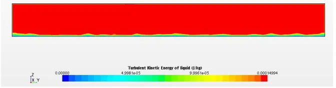
4. RESULTS AND DISCUSSION
Contour plot of turbulent kinetic energy (TKE) for liquid
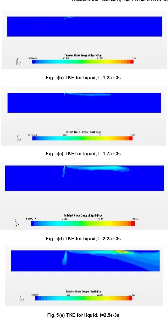
Fig. 5(b) TKE for liquid, t=1.25e-3s
Fig. 5(c) TKE for liquid, t=1.75e-3s
Fig. 5(d) TKE for liquid, t=2.25e-3s
Contour plot of turbulent kinetic energy for gas:
Fig. 6(a) TKE for gas, t=1e-3s
Fig. 6(b) TKE for gas, t=1.25e-3s with inlet region zoomed in
Fig. 6(c) TKE for gas, t=1.75e-3s with inlet region zoomed in
Fig. 6(e) TKE for gas, t=2.5e-3s with inlet region zoomed in
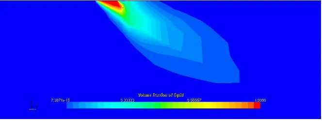
Contour plot of liquid volume fraction
Fig.7(a) Volume fraction of liquid, t=1e-3s with inlet region zoomed in
Fig. 7(b) Volume fraction of liquid, t=1.25e-3s with inlet region zoomed in
Fig. 7 (d) Volume fraction of liquid, t=2.25e-3s with inlet region zoomed in
Fig. 7 (e) Volume fraction of liquid, t=2.5e-3s with inlet region zoomed in
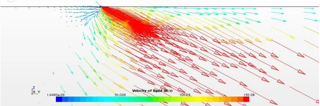
Velocity vector of liquid
Fig. 8(a) Velocity vector of liquid, t=1e-3s with inlet region zoomed in
Fig. 8(c) Velocity vector of liquid, t=1.75e-3s with inlet region zoomed in
Fig. 8(d) Velocity vector of liquid, t=2.25e-3s with inlet region zoomed in
Fig. 8 (e) Velocity vector of liquid, t=2.5e-3s with inlet region zoomed in
The results above show the motion of liquid jet inside the computational domain during the injection period indicated. This motion may somehow be affected by the gas-phase turbulence. Fig. 5(a) to Fig. 5(e) presents the turbulence of liquid-phase which is observed to be developed on both sides of its injection direction, and it was further observed in Figs. 8 (a) to 8 (e). That is the flow of liquid-phase begins to vary irregularly around the inlet area where eddies may be involved in causing the turbulence. Consequently, as the injection continues, such turbulence expands with the flow of liquid jet.
With its original turbulence, the motion of gas-phase is affected by the injected liquid but possibly varies little. It can be seen from Figs.
6(a) to 6(e) that the variation of turbulence for gas-phase is mainly centred in the region of the inlet during the injection process. In addition, analysing Figs 5 and 6 give an indication that the GDI engine with late injection may give rise to the two-phase flow with non-homogenous turbulent characteristics without the account of vaporisation in this simulation.
step was different under this transient simulation. The results also show that decreasing the injection velocity, the structure of spray tends to remain similar axisymmetric compared with higher velocities. Also, the distributions of turbulence for gas-phase seem to be centralised at inlet region which is consistent with the high-velocity situation.
The turbulent degrees of liquid-phase somehow
indicating the level of liquid disintegration are quite different between the two scenarios.
Conventionally, it is expected to acquire desirable rich mixture formation near the spark plug before the ignition in the GDI engine with late injection. The high volumes of the mixture near the vicinity of the inlet illustrate this phenomenon.
It was also observed that higher injection velocity which gives rise to the stronger turbulence of liquid produce better-atomized liquid droplets around that area with very lean concentration. Therefore, increasing injection velocity will bring about better atomisation for liquid fuel which may contribute to the improved mixture formation.
5. CONCLUSION
The GDI late injection period near the end of the compression stroke is modelled and the internal air tends to be turbulent initially. The liquid fuel in a form of jet injected from the nozzle (inlet) also appears to be turbulent flowing within air surroundings. The flow of liquid influences the flow of ambient air which also has a reverse effect. Hence different developments of turbulence for each phase are observed. The Eulerian multiphase model shows that the turbulence of each phase is tackled separately showing a non-homogeneous state. For liquid jet, droplets drift towards both sides of injection direction and owing to such drifting and
disturbance from environmental air, possibly eddies are detected and lead to the
turbulence consequently. The turbulence of liquid expands with the motion of droplets while for gas-phase the disturbing parts are centred in the inlet zone during the injection period. The asymmetric structure of spray is observed when the volume fraction of liquid is simulated and the effects of injection velocity are also investigated.
COMPETING INTERESTS
Authors have declared that no competing interests exist.
REFERENCE
1. Blessinger M, et al., Quantitative mixing measurements and stochastic variability of a vaporizing gasoline direct-injection spray. International Journal of Engine Research. 2015;16(2):238-252.
2. Costa M, Sorge U, Allocca L. Numerical study of the mixture formation process in a four-stroke GDI engine for two-wheel applications. Simulation Modelling Practice and Theory. 2011;19(4):1212-1226. 3. Fiengo G, et al., Basic concepts on GDI
systems, in Common Rail System for GDI Engines. 2013;Springer:17-33.
4. Wang C, et al., Impact of fuel and injection system on particle emissions from a GDI engine. Applied Energy. 2014;132:178-191.
5. Banerjee R, Kumar S. Numerical investigation of stratified air/fuel preparation in a GDI engine. Applied Thermal Engineering. 2016;104:414-428. 6. Aleiferis P, et al., On the effect of ambient
turbulence and thermodynamic conditions on fuel spray development for direct-injection spark-ignition engines. Flow, Turbulence and Combustion. 2015;95(1): 29-60.
7. Hasan A, et al., Control of harmful hydrocarbon species in the exhaust of
modern advanced GDI engines.
Atmospheric environment. 2016;129:210-217.
8. Costa M, et al., Study of mixture formation and early flame development in a research GDI (gasoline direct injection) engine through numerical simulation and UV-digital imaging. Energy. 2014;77:88-96. 9. Kumaravel K, et al., Evaluation of lean
operation limit on performance features of stratified charge gasoline direct injection
(GDI) engine. International Journal of Engineering Innovations and Research.
2014;3(5):635.
10. Bonatesta F, Chiappetta E, La Rocca A. Part-load particulate matter from a GDI
engine and the connection with combustion characteristics. Applied
Energy. 2014;124:366-376.
11. Lee S, Park S. Spray
atomization characteristics of a GDI injector equipped with a group-hole nozzle. Fuel, 2014;137:50-59.
injectors for different nozzle geometries. SAE Technical Paper; 2015.
13. Lefebvre AH, McDonell VG. Atomization and sprays. CRC press; 2017.
14. Gunasekaran J, Dhandapani S, A Comparison of Two Injectors in Mixture Preparation for a High Tumble GDI
Engine-A CFD Study. SAE Technical Paper; 2012.
15. Fiengo G, et al., Common rail system for GDI engines: Modelling, identification, and control. Springer
Science & Business Media; 2012.
16. Catapano F, et al., An experimental and numerical investigation of GDI spray
impact over walls at different temperatures. SAE Technical Paper; 2016. 17. Zhao F, Harrington DL, Lai MCD. Automotive gasoline direct-injection engines. Warrendale, PA: Society of Automotive Engineers. 2002;372:2002. 18. Sazhin S. Droplets and sprays. Springer.
2014:345.
19. Bayvel L. Liquid atomization. Routledge; 2019.
20. Arcoumanis C, et al., Modeling of pressure-swirl atomizers for GDI engines. SAE transactions. 1999:516-532.
21. CD-adapco U, GUIDE Star CCM+ Version 10.04. 08. CD-adapco; 2016.
© 2019 Amedorme and Apodi; This is an Open Access article distributed under the terms of the Creative Commons Attribution License (http://creativecommons.org/licenses/by/4.0), which permits unrestricted use, distribution, and reproduction in any medium, provided the original work is properly cited.
Peer-review history: