INTRODUCTION
Metrology is the science of measurement, and measurement is the language of science. Measurement is the comparison of given dimension obtained through a physical test with an assumed (assigned) reference unit. The result of measurement expressed as a number, shows the ratio of the unknown quantity to the selected measurement unit. This comparison is performed with the help of a measuring instrument1.
In the present day industrial world it is necessary to produce standard equipment, which can be repaired by replacement of the faulty parts. In addition, to keep cost low it is desired to have uniform products1, 2.
Every industry has a department which is responsible for the quality and product control.
DESIGN AND MODELLING OF A MODULAR BORE GAUGE AND FEM ANALYSIS FOR EVALUATION OF ITS LIFE CYCLE
F. Farhani*, B. Hemati and P. Boland
Mechanical Engineering Department,
Iranian Research Organization for Science and Technology (IROST), Tehran (Iran)
(Received, 29 October, 2005)
ABSTRACT
Accurate measurements and the associated instrumentation play vital role in the development of different industries. It is generally accepted that without special purpose measuring instruments, it would be impossible to repeat the work done by another individual in any field of research. Application of gauges as a substitute for the direct measurement methods can significantly enhance the manufactured parts verification process, both in terms of speed with which the process is performed, and also the desired accuracy with which the process must be done. On the other hand, the direct transfer of measurement data from the gauge to computer can further improve and reduce the tedious process of Statistical Process Control (SPC). To fulfil the above goals, we have used CAD software to perform a feasibility study for the design and modelling of various modular bore gauge mechanisms, considering the requirements of a precise measurement instrument. We studied several mechanisms, and selected the best mechanism for this purpose. Using FEM tools, a fatigue analysis was then performed to analyze a critical part in the instrument, which experiences the maximum fatigue due to continuous operation. The life cycle calculations for this critical part show that our design and analysis process has been satisfactory, and that the method can be used for the design of precise modular bore gauges.
Keywords: Measurement instruments, CAD software, modular bore gauge, FEM, Fatigue strength.
instrument, the knowledge of features and characteristics of the particular measuring instrument can result in fabrication of an instrument that can produce measurements with minimum errors.
A measuring instrument, depending on its application, has unique characteristics. However, the following parameters are the general requirements for any measuring instrument:
i) Accuracy and Precision
Accuracy of a measuring instrument is the difference between the mean of certain number of measurements of a quantity and the actual value of the measured quantity. The precision is the distribution population around the mean value. In other words, the measuring instrument should be able to repeat the same measurement with a high distribution population around the mean value of the measured value, and the mean value of measurements should be equal to the actual value of the measured quantity2.
ii) Sensitivity
Sensitivity is the slope of variation of the output to the variation of the input, and higher sensitivity results in higher precision1.
iii) Resolution
Resolution is the smallest measurable quantity, which a measuring instrument can detect and measure with a high degree of reliability.
iv) Repeatability
Another important parameter for a measuring instrument is its ability to return the same measurement results at different times or with similar inputs. This capability diminishes with time. In mechanical instruments this diminishing in repeatability is due to increased play between the sliding parts or bolt and nut, and in electrical instruments it is due to increased levels of temperature and noise1.
v) Measurement Range
It is the difference between the maximum and the minimum value detectable by the measuring instrument2.
Specific design parameters for a bore gauge The following specific design parameters are important as far as a bore gauge design is concerned:
• Watertight- resistant against coolant, soap water solution and chips produced as the result of machining,
• Resistance against shock and impacts, • Data Storage Capability and data transfer for Statistical Process Control (SPC),
• Simple to use- the operator can use the instrument without prior experience and with ease and without error.
Transducer
Today, electrical devices are used extensively in the measuring instruments. Almost every electrical property (resistance, capacity, induction coefficient, simple on-off switching) can be used in various amplifier circuits, and for performing linear measurements4. Transducers are classified as Contact and Non-contact types. Optical and Eddy Transducers are of Non-contact type, and Half-bridge Transformers (HBT) and Linear Variable-differential Transformer (LVDT) are of Contact type. The important parameters for selection of a transducer are size and cost5. On this basis we have selected LVDT for our work. The specifications of LVDT are given in Table - 1.
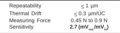
Table - 1: Specifications of LVDT
Repeatability 1 µm
Thermal Drift 0.3 µm/ÚC
Measuring Force 0.45 N to 0.9 N Sensitivity 2.7 (mVout /mVin)
Table - 2: Mechanical properties of the work piece Mechanical Property Value (MPa) Ultimate Stress (Sut) 1275 Yielding Stress (Sy) 1030
Modulus of Elasticity 207
Poisson Ratio 0.3
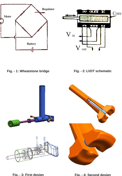
Fig. - 1: Wheatstone bridge
Fig. - 2: LVDT schematic
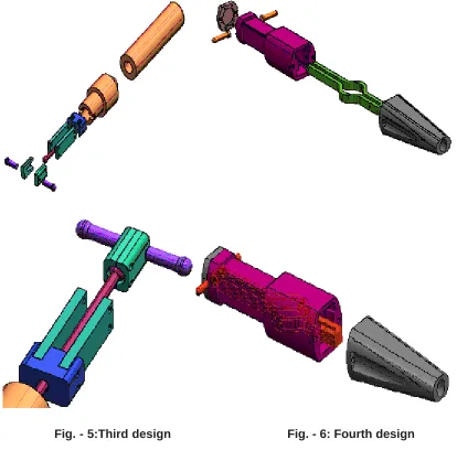
Fig. - 3: First design
Fig. - 4: Second design
Regulator
Battery
Meter
Core
V
in
Fig. - 5:Third design
Fig. - 6: Fourth design
circuit, the reading value is proportional to the battery voltage, which destabilizes the measuring instrument. For the correction of this instability, an inductive bridge is used. A special transformer called LVDT is used, in which impedance change is proportional to change in the core position. In other words, as shown in Fig. -2, the output voltage from LVDT is linearly proportional to the linear change in core position2, 6.
Design and Modelling of the Bore Gauge In order to select the best design, the following parameters were considered:
1. The ability to meet requirements outlined in section 1.11.
2. The transducer used must have small size and low cost5.
3. Low inertia and friction in the instrument’s mechanisms1.
4. Wide measurement range, i.e., it should be able to measure small diameter bores (of the order of few millimetres) as well as large diameter bores (of the order of 100 mm ), and it should be easily replaceable1, 2. 5. Manufacturability of parts to a high degree
of accuracy at low cost and using conventional machines.
As the first step in the design process, we have modelled four different designs of bore gauge, using the Unigraphics NX software7 (Figs.- 3, 4, 5, 6).
Fig. - 7:The FEM model with loading and supports
(Figs. - 3, 4, 5), the horizontal displacements of the probes has to be converted into vertical displacements, and the transducer is positioned at the end of the rod which converts the displacements mentioned above. This requirement for conversion of displacements does not fulfil the third item in the above list. In addition to that, these designs are difficult to manufacture. The second design has a small measuring range.
In the fourth design, the probe can move the finger directly (without any intermediate), and the transducer which is situated in the O-shape section (Fig. -4) is displaced, and the measurement is made. It is possible to change the measuring range by changing the probes, and for the large bores the lower part of the plug can be changed, too. Therefore, out of the four designs considered, the fourth design fulfils all of the above requirements, and hence it has been selected for further study and analysis.
The measuring device considered here is used for precision measurement and control of holes, with an accuracy of 1 µm, in mass produced high accuracy parts. The main parts of the bore gauge are:
• The main body made up of steel 1.0727, • The handle made up of plastic,
• Fingers made up of steel 1.0970, • The plug made up of steel 1.0727, • The probe made up of Tungsten Carbide.
The repeated opening and closing of the finger will result in failure of the finger due to fatigue. The fatigue strength of the finger has been calculated using FEM and the classical method, and its life cycle has been estimated on the basis of its calculated fatigue strength.
Calculation of Fatigue Strength Using FEM Analysis
For the fatigue analysis of fingers, they should be subjected to alternative loads, and the produced stresses should be determined. Therefore, prior to any fatigue analysis a static analysis, consisting of at least two load steps, should be done. Then, on the basis of stress contours, the critical nodes are identified and the evaluation of fatigue is performed for these nodes.
Nastran/Patran software. The mechanical properties of the work piece are presented in Table -2.
The governing equation for structural problems is of the following form:
(1)
The above equation is a general equation of motion, which consists of damping and inertial forces. For the linear static condition, since the load is constant and does not change with time, Equation (1) can be written as:
(2)
Where,
= Stiffness matrix
= Nodal displacement vector
= Loading vector
The finger has been meshed using the Tetra10 mesh. There are 3198 nodes and 1497 elements. A force of 10 N magnitude is applied on tip of the finger on both sides, and the supports are located at the end of the finger (Fig. - 7)8, 9.
We have considered the following assumptions in our static analysis of the finger: 1. Linear properties of the material: The material is considered as isotropic and homogeneous, and that the environment is continuous with no cracks.
2. Small displacements: on the basis of this assumption, if displacements exceed 20% of the plane thickness and 2% of the length, nonlinear analysis must be used.
3. Application of load is gradual: the finger is under static equilibrium, and if the application of load does not take place gradually, dynamic effects will appear. In other words, in this analysis impact loading has not been considered9.
In this analysis magnitude of displacements is directly proportional to magnitude of loading, and the superposition principle can be used for integration of the analysis results8.
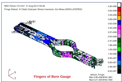
Fig. - 8: Von Mises stress analysis and maximum stress calculation
Fingers of Bore Gauge
Z X Y
default_Fringe: Max 4.95+008@Nd 1881 Max 6.21+005@Nd 1800 Fringe Default A1:Static Subcase: Stress Invariants, Von Mises-(NON-LAYERED)
The results of analysis of Von Mises stress has been shown in Figure (8). The maximum value of Von Mises stress is 495 MPa and occurs at the supports.
We have done analyses for steel types 1.0903, 1.0961, 1.7176, 1.7701 and 1.8159 [10]. However, the results obtained for steel type 1.0970 are more satisfactory, and therefore, we have presented the results for this type of steel.
Calculation of Fatigue Strength Using the Classical Method
The finger has a uniform cross section, and the maximum bending torque is applied on the end bend which has higher stress concentration. Therefore, there is a possibility of fracture in the finger bends. The following relations are used for calculation of fatigue strength [11]:
(i) Bending torque in the end bend:
(3)
(ii) Maximum fatigue strength
(4)
Where,
(5)
Here, h is the height and b is the width of the finger
The fatigue strength is equal to 464.7 MPa, which is very close to the value calculated using the FEM analysis. Additionally, the initial guess about the location of fracture or the maximum stress has been validated.
The Finger Life Cycle
To calculate the Endurance-Limit Modifying Factor, the following relation is used [11, 12]:
(6)
Where,
= endurance limit, calculated using Eqn. (7)
(7)
(with 15% generous coefficient of variation)
= surface factor.
It is obtained from graph [12]
= size factor (calculated using Equation (8))
(8)
c
K
= reliability factor
(with 90% reliability, Kc = 0.0897)
d
K
= temperature factor(calculated using Equation (9))
(9)
f
K
= miscellaneous-effects factor (calculated with Equation (10))(10)
Kt and q are obtained from graph [12].
= modifying factor for stress concentration
(calculated using Equation (11))
(11)
The following relation is used for calculation of life cycle:
(12)
Where,
the fatigue strength using the FEM is found to be 165 x 103 cycles, and the fatigue strength using the classical method is found to be 178 x 103 cycles. In view of the tenfold increase in applied force on the finger, the calculated life cycle is within acceptable range.
RESULTS AND DISCUSSION The following results can be highlighted: 1. Modelling process has proved to be
essential for making better decisions concerning the selection of various mechanisms based on constrains and requirements. It is also possible to optimize any selected mechanism.
2. Using the good interface between the modelling software and the FEM analysis
critical part, the finger. The life cycle determination has been done on the basis of the deformation in the finger, the material, and the acting forces and the supports conditions. The process has been repeated in order to arrive at an optimum life cycle. 3. The results of this study can be used for the
reduction of cost for performing tests on the instruments.
4. The fatigue strength has been calculated using FEM and classical method, and the results show that FEM calculations are more reliable as verified by the results of classical method.
5. As future work, the finger mechanism may be modified such that two transducers at a time can be used, which makes it possible to identify and measure the eccentricity of any bore in a single step.
1. R. Thompson: Fundamentals of
dimensional Metrology, 3rd Ed., 1952, (1990)
2. M.G. Dirpoosh, M.D. Mahmoodzadeh, and S.M. Ziaee: Precise Measurring Systems, (In Persian) (2002)
3. S. Kalpakjian: Manufacturing Processes for Engineering Materials, 3rd Ed., (1997) 4. D. Prenskey, R.L. Castellacis: Electronic
Instrumentation, 3rd Ed.
5. 375 Series AC/AC, Sentech WC,
Transformers Catalog, Web Site: WWW.sentechlvdt.com
REFERENCES
6. W.D. Cooper, A.D. Helfrick: Electronic Instrumentation and Measurement Techniques, 3rd Ed., Prentice-Hall, New Delhi, (1991)
7. Unigraphics NX Documentation, (2002) 8. Applied Finite Element Analysis, John Wiley
& Sons, (1984)
9. S. Kobayashi: Metal Forming and the Finite Element Method (1989)
10. Steel Website: http://www.matweb.com 11. Strength of Materials, 3rd ed., D. V. Nostrand
Co. Inc., New York, (1955)