B I O P H Y S I C S Copyright © 2020 The Authors, some rights reserved; exclusive licensee American Association for the Advancement of Science. No claim to original U.S. Government Works. Distributed under a Creative Commons Attribution NonCommercial License 4.0 (CC BY-NC).
Different motilities of microtubules driven by kinesin-1
and kinesin-14 motors patterned on nanopillars
Taikopaul Kaneko1, Ken’ya Furuta2, Kazuhiro Oiwa2, Hirofumi Shintaku1,3, Hidetoshi Kotera1,4, Ryuji Yokokawa1*
Kinesin is a motor protein that plays important roles in a variety of cellular functions. In vivo, multiple kinesin molecules are bound to cargo and work as a team to produce larger forces or higher speeds than a single kinesin. However, the coordination of kinesins remains poorly understood because of the experimental difficulty in controlling the number and arrangement of kinesins, which are considered to affect their coordination. Here, we report that both the number and spacing significantly influence the velocity of microtubules driven by non-processive kinesin-14 (Ncd), whereas neither the number nor the spacing changes the velocity in the case of high-ly processive kinesin-1. This result was realized by the optimum nanopatterning method of kinesins that enables immobilization of a single kinesin on a nanopillar. Our proposed method enables us to study the individual effects of the number and spacing of motors on the collective dynamics of multiple motors.
INTRODUCTION
Motor proteins convert chemical energy into structural changes and produce mechanical work necessary for various cellular processes in-cluding vesicle transport (1), cell division (2), muscle contraction (3), and beating of flagella and cilia (4). In vivo, motor proteins do not work alone but as a team (5–7). In intracellular transport, approxi-mately 10 motors coordinate to transport a cargo (8–10) and coop-erate to produce a higher speed or larger force than that by a single motor. The velocity of cargo with several kinesin motors increases by three- to fourfold compared to a single kinesin motor in vitro (11,12). Similarly, the force exerted by kinesin-14 motors increases with their number (13,14). In cell divisions, 20 to 100 motors are involved in assembling the spindle to segregate chromosomes (15). Approximately 104axonemal dynein molecules, assembled with a defined spacing of 24 or 96 nm, collectively produce the beating motion of a cilium or a flagellum (16,17). Evidently, to understand the physiological functions of motor proteins, it is necessary to know how the number and spacing of motor proteins influence their motility.
The effect of the number of motors on microtubule behavior has been investigated using a microtubule gliding assay because the num-ber of motors interacting with gliding microtubules can be estimated from the length of the microtubule and motor density on the surface (i.e., the number of motor molecules per unit area). Bielinget al.(18) found that the microtubule velocity decreased with an increase in motor density when a truncated kinesin-1 was used. Roostaluet al. (19) reported that the directionality of gliding microtubules could be switched by increasing the number of kinesin-5 proteins and argued that directionality was determined by the total number of kinesin-5 proteins interacting with the microtubule. These studies suggest that the number of motors is an important factor in the collective dynam-ics of motors.
The spacing between motors has also been shown to affect the collective dynamics of motors. Axonemal dynein molecules are
ar-ranged along the microtubule of cilia and flagella at equally spaced intervals (16,17). Using extract from cilia, Seetharam and Satir (20) reconstituted that the gliding of microtubules on axonemal dynein molecules is periodically arranged in vitro and found that the micro-tubules could slide at a high velocity (average of 196mm/s). As this measured velocity is an order of magnitude greater than the typical gliding velocity on a dynein-coated glass surface, where the spacing of axonemal dynein molecules is variable (21), it is thought that equal spacing between dynein molecules may be necessary to realize a higher velocity.
One disadvantage of a conventional gliding assay is that it cannot distinguish the effects of direct and indirect interactions between motors on their collective dynamics. Direct interactions caused by steric hindrance between adjacent motors lead to detachment or paus-ing of motors, decreaspaus-ing the velocity of microtubules (22). An in-direct interaction occurs when one motor’s activity influences other more distant motors transporting the same microtubule (6). When a microtubule is transported by multiple kinesins, some of them gen-erate a force that acts in a direction that is opposite to the moving di-rection of the microtubule because not all kinesins are synchronized. Direct interactions could be eliminated by increasing the space be-tween the motors. Therefore, to investigate the individual effects of direct and indirect interactions, the spacing between motors could be controlled.
The mechanisms explaining how the number and spacing of motors affect their collective dynamics remain poorly understood, pri-marily because of the experimental difficulties in controlling these pa-rameters in vitro. Using flat surfaces, the number and spacing of motors can be controlled by varying their concentration and the length of the microtubules. However, the estimated number of motors interacting with a microtubule is less deterministic, because motors are stochastically distributed on the surface. Although DNA origami scaffolding allowed us to precisely define the number and spacing of motors (13,23–25), only up to 10 motors can be controlled, which is much lower than the number in vivo. It is necessary to develop a method to modulate the number and spacing of motors in vitro.
Several studies have addressed the difficulty of controlling the number of motors using micro/nanopillars. Lardet al.(26,27) dem-onstrated that the number of myosin interacting with an actin fila-ment can be controlled by immobilizing myosin molecules on a
1Department of Micro Engineering, Kyoto University, Kyoto Daigaku-Katsura, Nishikyo-ku, Kyoto 615-8540, Japan.2Advanced ICT Research Institute, Nation-al Institute of Information and Communications Technology, 588-2, Iwaoka, Nishi-ku, Kobe, Hyogo 651-2492, Japan.3Cluster for Pioneering Research, RIKEN, 2-1, Hirosawa, Wako, Saitama 351-0198, Japan.4RIKEN, 2-1, Hirosawa, Wako, Saitama 351-0198, Japan.
*Corresponding author. Email: ryuji@me.kyoto-u.ac.jp
on September 17, 2020
http://advances.sciencemag.org/
nanowire array. However, because myosin molecules were immobi-lized not only on the top of nanowires but also on the substrate and sides of the nanowires, actin filaments frequently glided along the sides of the nanowires down to the substrate, resulting in short obser-vation times. In addition, their method is less deterministic because multiple motor molecules were attached on the tops of the large-diameter (150 to 170 nm) nanowires. Rooset al.(28) took an approach similar to Lardet al., selectively immobilizing kinesin molecules on the tip of micropillars made of polydimethylsiloxane. However, many kinesin molecules were attached to a single micropillar owing to its large diameter (1 to 5mm).
Here, we propose the nanopatterning method of kinesins to ac-curately determine the number (10 to 100 motors per microtubule) and spacing (200 to 1000 nm) of kinesin motors. Because we used smaller nanopillars (50 nm in diameter) to immobilize only a single kinesin molecule per pillar, we can precisely define the number of motors and the spacing of the motors interacting with a microtubule. Moreover, this method enables us to perform the microtubule gliding assay at a much lower motor density (<10 molecules/mm2) than that required for the conventional gliding assay with flat surfaces (20 to 10,000 molecules/mm2) (18). This makes it possible to study the rela-tionship between the number and velocity of motors in the range of 3 to 100 motors, similar to the number of motors working together in vivo (29). In addition, our method enables us to isolate the effects of indirect interactions between motors because the distance be-tween them is greater than twice the length of a kinesin molecule. We found that the number and spacing of kinesin molecules sepa-rately affect the microtubule velocity in the case of nonprocessive kinesin-14, whereas the velocity is independent of both the number and spacing for processive kinesin-1. The proposed patterning method facilitates a new assay that can be used to investigate how the number and spacing of motors affect the collective dynam-ics of multiple motors.
In addition to enabling the study of the relationship between ve-locity and the number and/or spacing of motors, our method has the potential to guide microtubules along nanopillars and motivate prac-tical usage of motor-driven bio-nano/microdevices (30). The micro-tubule-kinesin system can be combined with microfluidics and used as a molecular transporter, sorter, concentrator, and detector. The directional control of gliding microtubule shuttles has been a chal-lenge that has hampered practical usage of microtubule-kinesin, as microtubules glide in random directions owing to Brownian motion of the free leading tip (31). Although a fabricated track can control the gliding direction of microtubules, the precision is still limited up to a few micrometers, and the efficiency of microtubule transport is deteriorated by frequent sidetrack of microtubules. In this study, we demonstrate that the gliding direction is defined with high precision by defining the position of each kinesin with nanometer-scale precision. Therefore, our method can also be used to control the di-rection of gliding microtubules and drive the practical usage of microtubule-kinesin systems.
RESULTS AND DISCUSSION
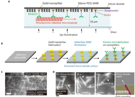
Nanofabrication of gold nanopillars and selective immobilization of kinesin molecules on self-assembled monolayer–modified surfaces
Kinesin molecules were selectively immobilized on gold nanopillars as illustrated in Fig. 1A. Gold nanopillar arrays were fabricated on a
silicon dioxide substrate by electron beam lithography and lift-off processes, followed by the passivation of a silicon dioxide surface with a silane–poly(ethylene glycol) (PEG) self-assembled monolayer (SAM) (Fig. 1B and fig. S1A). To attach only one kinesin molecule to a nanopillar, we designed the diameter of the nanopillars to measure 50 nm. By optimizing the smallest spacing in the nanofabrication processes, nanopillar arrays with spacing ranging from 200 to 1000 nm were fabricated (fig. S1B). SEM observations confirmed that the diameters of the nanopillars were close to the designed value (55.7 ± 4.17 nm, mean ± SD,n= 30) (fig. S1C).
Before performing a gliding assay on the pillars, we confirmed that both kinesin-1 and kinesin-14 could be selectively immobilized only on a planar gold surface and not on the passivated silicon dioxide surface. On the gold surface, where biotinylated kinesin-1 was immo-bilized via nonspecifically absorbed streptavidin, the microtubule ve-locity was recorded as 0.75 ± 0.02mm/s (mean ± SD,n= 5). No microtubule was found on the silicon dioxide surface because of the silane-PEG SAM (32). In a control experiment using a glass substrate, where kinesin-1 was immobilized via streptavidin and biotinylated bovine serum albumin, the microtubule velocity was recorded as 0.42 ± 0.02mm/s (mean ± SD,n= 5). When the same measurement was conducted using kinesin-14, recorded velocities were 0.123 ± 0.015 mm/s (mean ± SD, n= 5) on a gold surface and 0.091 ± 0.003mm/s (mean ± SD,n= 5) on a glass surface. The silane-PEG SAM–modified surface also suppressed microtubule absorption in the kinesin-14 assay.
It is known that the velocity strongly depends on temperature (33), the construct (length) of kinesin (18), and the surface density of the motors (18). Therefore, measured velocities are compared to previous studies conducted under conditions similar to ours. Our recorded ve-locity on a kinesin-1–coated glass surface (0.42 ± 0.02mm/s) is in agreement with the≈0.43mm/s obtained in a previous study (18). Ex-perimental conditions for our study were similar to theirs: a surface density of≈1000 molecules/mm2using a truncated kinesin-1 (Kin401, amino acids 1 to 401; 1 to 465 in this study) at 26°C (23° to 25°C in this study). Velocity on a kinesin-14–coated glass surface (0.091 ± 0.003mm/s) is slightly lower than a previously reported value (0.135 ± 0.006mm/s) (34). We used the same truncated kinesin-14 (amino acid 195 to 700) as Furutaet al., so the difference in velocity may have come from their use of green fluorescent protein tag or a difference in the surface density of motors, since theirs was not controlled.
Our results show that the velocities on kinesin-1–or kinesin-14– coated gold surfaces are higher than those on glass surfaces. A pos-sible explanation is the elevation of temperature near the gold surface owing to the absorption of excitation light. According to our previous study (35), the temperature on a gold surface is elevated from 23°C to 28°C when the surface is illuminated by excitation light with an ir-radiance of 7.2 W/cm2(equivalent to the intensity we used in this study), resulting in an increased velocity compared to that on a glass surface. Motility functions of kinesin molecules were retained after the selective patterning on a gold surface. Therefore, we decided to im-mobilize kinesin molecules on gold nanopillars via nonspecifically ab-sorbed streptavidin.
Microtubule gliding assay on kinesin-1–or kinesin-14–immobilized nanopillars
A microtubule gliding assay was performed to verify the selective immobilization of kinesin molecules on gold nanopillars. It was found that, in the gold nanopillar region where kinesin-1 motors were
on September 17, 2020
http://advances.sciencemag.org/
immobilized, many microtubules attached to the surface and glided smoothly (Fig. 1C and movie S1). On the other hand, we found no microtubule attachment within the silicon dioxide region. When the microtubules crossed the boundary from the nanopillar region and entered the silicon dioxide region, they detached from the surface (Fig. 1D and movie S2). The same behavior was observed on the kinesin-14–patterned surface (fig. S2 and movies S3 and S4). These results support the idea that kinesin molecules exist only within the gold nanopillar region.
To evaluate the number of kinesin molecules attached to the nano-pillars, we observed the behavior of short microtubules on patterned kinesin-1. We used kinesin-1 because it is a highly processive motor, and a single molecule has the ability to move a microtubule. Short mi-crotubules (1 to 5mm) were introduced into a flow chamber where kinesin-1 was patterned by 5-mm spacing nanopillars. We observed that several microtubules exhibited pivoting motions on an anchored point (fig. S3B), which is known to be observed when a microtubule is driven by a single kinesin-1 molecule (fig. S3A) (36). In addition, the microtubules showed a gliding motion at the anchored point (fig. S3D). These results indicated that a single kinesin-1 molecule was attached to a pillar and drove the microtubules.
As kinesin-14 is not a processive motor, it frequently detaches from microtubules in the presence of adenosine triphosphate (ATP). For this reason, we evaluated the number of kinesin-14 on a pillar by the
same method for kinesin-1 but in the absence of ATP (see Materials and Methods for detail). We observed pivoting motions of microtubules at an anchored point (fig. S3C), indicating that a single kinesin-14 molecule was attached to a pillar.
As the hydrodynamic radius of kinesin is approximately 10 nm (37), six kinesin molecules can be immobilized on a pillar with a di-ameter of 50 nm. However, this assumption is inconsistent with our finding that only a single kinesin was attached to each pillar. Here, casein may have a significant role in decreasing the number of kinesin molecules on a pillar, because it forms micelles with a hydrodynamic radius of ~12 nm and attaches to pillars (38).
Our result also indicates that there are very few, if any, pillars with more than one motor. If pillars had more than one motor, then we would have observed a smooth gliding of short microtubules. How-ever, we did not observe this behavior; we observed only instances of pivoting motions.
To statistically examine whether all nanopillars capture a single kinesin molecule, the average spacing between kinesin motors immo-bilized on nanopillars can be discussed. When a short microtubule glides on a kinesin-1–coated surface, it frequently binds to a single kinesin-1 molecule and displays a pivoting motion around the motor (39). The average distance travelled by the microtubule between successive rotations depends on the length of the microtubule and the average spacing between kinesin-1 motors. Hence, the average Fig. 1. Nanopatterning of kinesin molecules by selective immobilization of kinesin on gold nanopillars.(A) Schematic illustration of nanopatterned kinesin molecules. (B) The experimental procedure of nanopatterning of kinesin molecules. (C) Fluorescence image of microtubules gliding at the boundary of the passivated silicon dioxide region and the kinesin-1–patterned region on gold nanopillars. Scale bar, 10mm. (D) Sequential images of a microtubule at the boundary between the nanopillar region and silicon dioxide region. Scale bar, 2mm.
on September 17, 2020
http://advances.sciencemag.org/
distance between motors <dk> was derived using the following equation (40)
<S>¼Lþ2<dk>
Lþ3dk
<dk>2
L e
L
dk1 L <dk>
ð1Þ
Here, <S> is the average distance travelled between pivots, andLis the length of the microtubule. If the measured average spacing between motors is equivalent to the spacing of nanopillars (dp), then we can
as-sume that each nanopillar has a kinesin molecule. Previously, we de-monstrated a selective immobilization of kinesin-1 on a nanopillar array via thiol-PEG-biotin SAM and measured the average spacing be-tween motors (41). When the diameter of the pillars was 50 nm, the measured spacing was 99.2 ± 4.2 nm for pillars designed with 100-nm spacings. However, the difference between the measured and designed spacings increased when the diameter of the pillars was 100 nm (267 ±
10 nm for 300-nm spacing; 452 ± 21 nm for 500-nm spacing). These results indicate that pillars with diameters of 50 nm have only a single kinesin molecule, whereas multiple kinesin molecules can be immobilized on pillars with diameters of >100 nm. Although we immobilized kinesin molecules via a different method (nonspecific absorption of streptavidin), we are able to assume that almost all the nanopillars have a single kinesin molecule in the current study.
Our method enables us to conduct microtubule gliding assays at an extremely low motor density (1 to 10 molecules/mm2), which can-not be done in a conventional gliding assay on a flat glass surface (20 to 10,000 molecules/mm2) (18). This can be explained by the difference in the number of motors interacting with a microtubule. On a flat sur-face, motors are stochastically immobilized and attach to a micro-tubule only when the distance between the longitudinal axis of the microtubule and a motor is less than 45 nm (42). Therefore, the num-ber of motors attached to the microtubules can be calculated as (2 × 0.045mm) ×r= 0.09r(molecules/1-mm microtubule). Here,ris the
Fig. 2. Alignment of microtubules on patterned kinesin molecules.(A) Fluorescence image of aligned microtubules on patterned kinesin-1 (left) and corresponding illustration of microtubules and nanopillars (right). The spacing between the pillars,dp, is 500 nm. Scale bar, 2mm. The illustration is not to scale. (B) The definition of the orientation angle of microtubules.dpindicates the designed spacing between pillars. (CtoF) The distribution of angles between microtubules and line A on patterned kinesin-1 in (C) BRB80 and (D) BRB12 and on patterned kinesin-14 in (E) BRB80 and (F) BRB12.
on September 17, 2020
http://advances.sciencemag.org/
surface density of the motors (molecules/mm2). On a nanopillar array, a microtubule glides on aligned pillars as discussed in the following sections. When focusing on a microtubule gliding in the direction of highest pillar density (Fig. 2B, line A), the number of motors attached to the microtubule can be calculated as 1/dp= 0:66pffiffiffir(molecules/ 1-mm microtubule). Here, we used the relationship between the spacing of nanopillars and the surface density of nanopillars (motors):dp¼
ffiffiffiffiffiffiffiffiffiffiffiffiffiffiffiffiffiffiffi 2=rsin60° p
¼1:52=pffiffiffir. Therefore, when the density is set tor= 1.0 molecule/mm2, a 10-mm microtubule can bind to only≈1 motor on a flat surface, which easily leads to detachment of the microtubules from the surface. However,≈7 motors can support microtubule gliding on a nanopillar array, resulting in stable gliding of microtubules. One advantage of our method is that the gliding assay can be conducted at such a low motor density (3 to 100 motors per microtubule), similar to the number of motors working together in vivo (29).
Compared to previous studies using a micro/nanopillar array (26–28), our method allows us to more accurately count the motors and define their spacing. Even in studies with a pillar array, motors coated all surfaces, including the substrate and sidewall of the pillars (26,27). This resulted in actin filaments gliding unpredictably across surfaces. However, in our study, the SAM coating and SiO2substrate prevented nonspecific binding and limited microtubule gliding to the tops of pillars. In addition, we used smaller nanopillars (50 nm in di-ameter) than previous studies (> 150 nm in didi-ameter) to immobilize only a single kinesin molecule on each nanopillar. Therefore, our assay continued for enough time to study the relationship between the veloc-ity and the number or spacing of motors. The method can be applied to kinesin-microtubules, actin-myosin, and other motors.
Alignment of microtubules on patterned kinesin molecules
We measured the orientation angle of microtubules with two kinds of kinesins (kinesin-1 or kinesin-14), two buffers with different ionic strengths (BRB12 or BRB80), and eight kinds of pillar spacings (300 to 1000 nm). Figure 2A shows the fluorescence image and the schematic illustration of microtubules on patterned kinesin molecules. The angles of the microtubules are defined with respect to the solid red lines (Fig. 2B, line A) connecting two adjacent pillars with the designed spacing,p, which ranges from−30° to +30°.
We found that there are two populations of microtubules indicated by the two peaks in the probability graph in Fig. 2 (C to F): one glides in the direction of 0° and the other glides in the direction of ±30°. The former peak corresponds to the main population of the microtubules that glide along line A. The latter corresponds to the subpopulation of the microtubules moving along line B, as shown in Fig. 2B. These two populations of microtubules are independent of the type of motors, the ionic strength of the buffer, and the spacing of the pillars (Fig. 2, C to F, and fig. S4, A to D). Fluorescence images of aligned micro-tubules under each condition are summarized in fig. S4 (A to D). As the persistence length of 4 to 8 mm is much larger than the pillar spacings, it is evident that most microtubules keep gliding straight once they start gliding on aligned pillars (43,44). In addition, the mi-crotubules are more likely to land in the directions of lines A and B, as the microtubules can bind to larger number of kinesin molecules in this region than in other directions (fig. S5, A and B). This is the reason why microtubules are settled in these two directions, and two peaks can be observed in Fig. 2 (C to F).
The degree of microtubule alignment becomes higher with an in-crease in the spacing of the pillars, reaching a maximum at a spacing of
700 nm in any condition (Fig. 2, C to F, and fig. S4, A to D). When the spacing between pillars is small, microtubules land not only in the di-rection of the two lines A and B but also in other didi-rections because they can bind to enough kinesins to remain on the surface. For exam-ple, a microtubule with a length of 10mm lands in other than the two directions and binds only to ~2 kinesin molecules in the case of a 700-nm pillar spacing, whereas it can bind to ~12 kinesin molecules in the case of a 300-nm spacing (fig. S5B). This is why the height of the peaks increases when the spacing of the pillars increases. In the case where spacing between pillars is equal to or more than 700 nm, we found that many microtubules changed their gliding directions by touching pillars or the silicon dioxide surface owing to tip fluctuation. Numerical simulation (see the next section for details) reveals that the tip thermally fluctuates by 37.9 nm (3× SD) at a 700-nm spacing. Therefore, when microtubules fluctuate in thezdirection, their tip can easily touch the substrate as the pillar height (the chromium and gold thickness) is only 23 nm. When the leading tip touches the sub-strate, the tip would be pinned on the surface, while the microtubule rear end continues to move forward, resulting in rotation of the micro-tubule around the pinned point and a change in the gliding direction. The ionic strength of the motility buffer also influences the degree of microtubule alignment. The population of microtubules that moves along line A or line B is larger in BRB80 buffer than in BRB12 buffer on both the kinesin-1–patterned surface (Fig. 2, C and D, and fig. S4, A and B) and the kinesin-14–patterned surface (Fig. 2, E and F, and fig. S4, C and D). This can be explained by the difference in the off-rate
Fig. 3. Simulation of a fluctuating leading tip of microtubules.(A) Schematic illustration of a fluctuating tip of the microtubule (left) and representative traces of the simulated shape of the tip (right). Traces were obtained by 500 runs of a simu-lation. (B) Probability density function of the displacement of the tip inydirection.
L, the length of a free tip;dp, the spacing between pillars.n> 10,000.
on September 17, 2020
http://advances.sciencemag.org/
of kinesins from microtubules. As a run length of kinesins decreases with increasing ionic strength (34,45), it is suggested that the off-rate increases with increasing ionic strength. In addition, the off-rate is known to in-crease when neck linkers of kinesin molecules are extended (42,46). Thus, the microtubules detached more frequently from the surface in BRB80 than in BRB12 if they landed in other than the two directions. Therefore, in BRB80, it is observed that most of microtubules continue to attach to kinesin molecules in the directions of lines A and B rather than in other directions, and the degree of microtubule alignment increases.
We also found that the degree of the microtubule alignment is higher on the kinesin-14–than on kinesin-1–patterned surface: The height of peaks at 0° and ±30° are higher on kinesin-14 (Fig. 2, E and F) than kinesin-1 (Fig. 2, C and D) in both BRB80 and BRB12. This is because kinesin-14 has a smaller detachment force (i.e., stall force) than kinesin-1: <1 pN for kinesin-14 (13) and ~6 pN for kinesin-1 (47). As the load applied to kinesin heads increases with the exten-sion of neck linkers, microtubules are detached more frequently from the kinesin-14–patterned surface than from the kinesin-1–patterned surface when the microtubules land in other than the two directions. A run length of motors also plays a role in aligning microtubules along pillars. Kinesin-14 has a shorter run length (≈−400 nm) than kinesin-1 (≈1600 nm) (34). The shorter run length causes rapid de-tachment of microtubules from the surface when a microtubules lands in other than the two directions.
In summary, the microtubules were highly aligned on patterned kinesins according to the pillar arrangement. The degree of micro-tubule alignment increases with (i) an increase in spacing and reached a maximum at a spacing of 700 nm; (ii) an increase in the ionic strength of the buffer solution; (iii) a decrease in the stall force of the motors; and (iv) a decrease in the run length of motors.
Simulating thermal fluctuation of the free tip of a microtubule on patterned kinesins
Next, we simulated the fluctuation of the leading tips of microtubules and investigated how the microtubules aligned along the pillars (Fig. 3A). Here, the microtubule is assumed to move along line A (Fig. 2B), and the free tip is considered as a cantilever beam tethered at one end (31). The length of a free tip,L, is equal to the spacing of the pillars,dp.
Figure 3B shows the probability density functions of displacement of the tip in theydirection for the 300- and 1000-nm pillar spacings. It is obvious that microtubules glide toward pillar A because the prob-ability is maximum aty= 0 nm, resulting in the peaks at 0° as shown in Fig. 2 (C to F). Next, we evaluated the amplitude of thermal fluctuation by comparing the SD of the displacement of the tip: SD is calculated as 3.54 nm fordp= 300 nm and 21.2 nm fordp= 1000 nm. The distance between pillar B and the microtubule is 0.865dpas shown in Fig. 3B and is calculated as ~260 nm fordp= 300 nm and ~870 nm fordp= 1000 nm. This indicates that the distance between pillar B and the
Fig. 4. Behavior of microtubules that changed travel direction on patterned kinesins.(AtoD) Representative sequential images of the microtubules. Scale bars, 5mm (A)“I. Collision and unchanged”: A microtubule did not change direction after collision; (B)“II. Collision and changed”: A microtubule changed direction after a collision. The white arrows indicate the leading tip of the microtubule. The white dashed arrows show the direction of microtubule gliding. The yellow arrows indicate the point of collision; (C)“III. Spontaneous”: A microtubule spontaneously changed its gliding direction. The yellow arrows indicate the position in which the leading tip changed its direction; (D)“IV. Pinning”: A microtubule changed direction because the leading end was pinned. (E) Frequency of the events (I) to (IV) on patterned kinesin-1 and kinesin-14.
on September 17, 2020
http://advances.sciencemag.org/
microtubule is more than 40 times larger than the amplitude of the free tip. Therefore, the possibility that the end of a free tip moved to the position of pillar B is zero.
The amplitude of thermal fluctuation can also be analytically cal-culated by the effective elastic constant of the tip asK= 3kMT/dp3and the fluctuation amplitude ass= ffiffiffiffiffiffiffiffiffiffiffiffiffiffikBT=K
p
, wherekBis the Boltzmann constant, andTis the temperature in the experiments (298 K). With this calculation,s= 3.51 nm forp= 300 nm ands= 21.4 nm forp= 1000 nm, which is consistent with our simulation results and confirms the adequacy of our simulation model.
Together, the numerical simulation indicates that the microtubules move along the straight lines (Fig. 2B, line A) corresponding to the pillars when kinesin molecules are immobilized only on pillars. How-ever, we observed that some microtubules changed their direction of gliding. To find an explanation for this contradiction, we investigated how the microtubules changed their gliding directions on patterned kinesin molecules.
Behavior of microtubules that changed their direction of gliding on patterned kinesin molecules
We carefully observed the behavior of microtubules on patterned kinesin molecules and investigated how the microtubules changed their direction of gliding. We found that events related to changes in the gliding direction can be classified into four types: (I) collision and unchanged, (II) collision and changed, (III) spontaneous, and (IV) pinning.
Figure 4 (A to D) shows the sequential images of microtubules that represent the events (I) to (IV). (I)“Collision and unchanged”is the event where the leading tip of a microtubule collides with other microtubules but does not change its gliding direction (Fig. 4A). (II) “Collision and changed”represents the event where the tip collides with other microtubules, and the microtubule changes its direction of gliding (Fig. 4B). In detail, the tip detached from the surface, glided over the other microtubules, and then exhibited Brownian motion. Last, the tip reattached to a kinesin in a different direction from the initial one and kept gliding (Fig. 4B, 16 to 20 s). (III)“ Spon-taneous”represents the event where the leading tip spontaneously changes its gliding direction by Brownian motion without colliding with other microtubules (Fig. 4C). (IV)“Pinning”indicates the event where the leading tip is temporally pinned on the surface, and the microtubule starts rotating around the pinned point and changes its gliding direction (Fig. 4D).
Figure 4E shows the frequency of each event, i.e., the number of observations for each event per second, on patterned kinesin-1 and kinesin-14. The sum of the frequency of (II) to (IV) indicates how many times the microtubules changed their gliding directions per second: 0.023 s−1on kinesin-1 and 0.003 s−1on kinesin-14. Micro-tubules changed their gliding directions on kinesin-1 at a frequency that was seven times higher than that on kinesin-14. On kinesin-1, the change was mainly caused by Collision and changed (0.017 s−1) and the effects of Spontaneous (0.006 s−1), and Pinning were neg-ligible (0.0005 s−1). On kinesin-14, the frequencies of Collision and changed (0.001 s−1) and Spontaneous (0.002 s−1) were almost the same and that of Pinning was also negligible.
According to these results, the collision of the leading tip (II. Collision and changed; Fig. 4B) is the main reason for the change in direction observed in the experiments but not in the numerical simulation. Although the frequency of the Spontaneous event was not zero in the experiments, the low frequency can reasonably
ex-plain why no microtubule could bind to a kinesin on pillar B in the simulation.
One possible reason why we observed Spontaneous events in the experiment, but not in the numerical simulation, is the underestimation of the amplitude of the free tip of a microtubule in the simulation. We assumed that the microtubule was tightly clamped to pillars, and the tip could be considered as a cantilever rigidly fixed at the frontmost motor. However, the stalk domain of a kinesin molecule is flexible in the experiment (42), and thus, the tip of microtubule is rather loosely clamped to the pillar, causing a larger fluctuation than that seen in the simulation. To estimate the amplitude of fluctuating tip more accu-rately, it will be necessary to construct a simulation that considers the elasticity of kinesin molecules.
Investigating the relationship between microtubule velocity and the number or spacing of motors
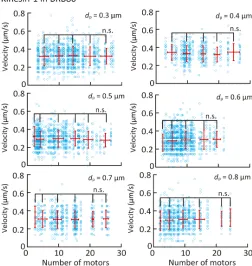
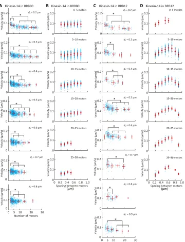
Figures 5 and 6 (A and B) show the dependence of the microtubule velocity on the number and spacing of kinesin-1 and kinesin-14 motors in the BRB80 buffer. We assumed that only a single kinesin molecule is attached to a nanopillar for both the kinesin-1 and kinesin-14 cases, according to the observed pivoting motion of short microtubules on nanopillars. The velocity was found to be independent of the number of kinesin-1 motors in the range of 3 to 30 motors and spacing of the kinesin-1 motors (Fig. 5 and fig. S6). In contrast, the velocity decreased within the range of 3 to 10 kinesin-14 motors and reached a plateau of over 10 motors (Fig. 6A). On the other hand, the velocity is independent of the spacing for kinesin-14 motors (Fig. 6B).
Figure 6 (C and D) shows the dependence of the microtubule velocity on the number and spacing of kinesin-14 motors in BRB12
Fig. 5. Effect of the number and spacing of kinesin-1 proteins on microtubule velocity in BRB80 buffer.Blue open circles represent individual measurements, and red points represent the average velocity binned into five-motor intervals. Means ± SD; n.s., not significant (Steel-Dwass test).
on September 17, 2020
http://advances.sciencemag.org/
buffer. Unlike in the BRB80 buffer, in the BRB12 buffer, both the num-ber and spacing of kinesin-14 motors affect the microtubule velocity. In BRB12 buffer, such as in the BRB80 buffer (Fig. 6A), the velocity decreased with an increase in the number of kinesin-14 motors (Fig. 6C). On the other hand, the velocity increased with an increase in the spacing until the spacing reached 0.6mm and decreased with an in-crease in the spacing of over 0.6mm (Fig. 6D).
The relationship between the microtubule velocity and the num-ber of kinesin-1 motors has been examined in previous studies. Bielinget al.(18) reported that, when a truncated kinesin-1 (amino acid residues 1 to 401) was used, the microtubule velocity
sharp-ly decreased with an increase in motor density in the case of high motor density (>500 molecules/mm2) and slightly decreased with an increase in motor density in the case of low motor density (<500 molecules/mm2). In our experiments, a truncated kinesin (amino acid residues 1 to 465) was used at a very low-density range owing to the patterning (2 to 58 molecules/mm2) and could not be investigated with a glass substrate. Therefore, our experiment indicates that velocity is independent of the number and spacing of motors at such a low motor density.
The relationship between the microtubule velocity and the num-ber of kinesin-14 motors was also evaluated in a previous study. Fig. 6. Effect of the number and spacing of kinesin-14 proteins on microtubule velocity.(AandB) Dependence of microtubule velocity on (A) the number of kinesin-14 proteins and (B) the spacing of kinesin-14 proteins in the BRB80 buffer. (A and B) Dependence of the microtubule velocity on (A) the number of kinesin-14 proteins and (B) the spacing of kinesin-14 proteins in the BRB12 buffer. Blue open circles represent individual measurements, and red circles represent the average velocity binned into five-motor intervals. Means ± SD; *P< 0.05 (Steel-Dwass test).
on September 17, 2020
http://advances.sciencemag.org/
Furutaet al.(13) revealed that the velocity of kinesin-14 motors was independent of the number of motors in the range of 1 to 4 motors. Lüdeckeet al.(14) examined the relationship between the velocity at which a microtubule glides on a kinesin-14–coated surface and the length of the microtubule. They found that the velocity was independent of microtubule length and thus motor number. When Lüdeckeet al.performed the assay using >1-mm microtubules on a surface coated with a saturated kinesin-14 motor (i.e., the density of the motor was≈4000 molecules/mm2) (48), their results indicated that the velocity is independent of motor number for >50 motors. Our results revealed that the velocity decreased from 3 motors to 10 motors and was constant in the range of 10 to 30 motors (Fig. 6, A and C), which fills the gap of motor number between two studies (13,14). Together, our studies reveal that velocity is independent of motor number in the range of 1 to 3 motors, decreases in the range of 3 to 10 motors, and is again independent at >10 motors. The dependency of velocity on the number and spacing of kinesin-14 motors also agrees with a previous study (49), which reported that the velocity decreased with increasing kinesin-14 density. Braunet al. attributed the decrease in velocity to the direct interaction (steric hin-drance) between motors but not to the indirect interaction between motors bridged by a solid microtubule structure. However, in our sys-tem, motors cannot directly interact on the nanopillar array because they are separated by a distance of more than 200 nm, which is more than twice as long as the roughly 60-nm kinesin stalk (50). Therefore, the decrease in velocity with an increasing number and spacing of motors is explained by the indirect interaction between motors through microtubules.
The velocity decreased with an increase in the number of kinesin-14 motors in the range of 3 to 10 motors (Fig. 6, A and C). This can be explained by the greater diffusive motion of kinesin-14 motor domains along a microtubule (34); unlike kinesin-14, kinesin-1 is known as a processive motor. The construct of kinesin-14 that was used in this study has two microtubule binding domains (MTBDs): The first MTBD, which is referred to as the motor domain, is at the C terminus, and the second MTBD is at the N terminus. However, the kinesin-14 motors on the nanopillars could interact with a microtubule only via the first MTBD, because the N terminus was immobilized via streptavidin-biotin binding. Furuta and Toyoshima (34) generated a kinesin-14 construct without the second MTBD by truncating the N terminus and calculated the diffusion coefficient (D= 7.1 × 10⁴nm2/s) and the mean velocity (v=−20 nm/s) in the BRB12 buffer by the quadratic fit [msd(t) = 2Dt+v2t2+C], wheretis the time andvis the mean velocity. This calculation indicates that the first MTBD of the kinesin-14 motor, compared to kinesin-1 (D= 0.48 × 10⁴nm2/s,v= 690 nm/s), shows significant diffusive motion along a microtubule (34).
The diffusive motion of kinesin-14 motors implies that the motors hinder each other’s movement during collective transport. When multiple kinesin-14 motors transport a microtubule, a fraction of motors move toward the plus end of the microtubule owing to their diffusive motion, while most of the motors move toward the minus end. According to a previous study, kinesin-14 motors generate a drag force when they are pulled backward (13). This indicates that kinesin-14 motors that move to the plus end hinder the movement of the microtubule by transmitting the drag force through the mi-crotubule. Such an indirect interaction via a microtubule causes the decrease in velocity observed on the nanopillar array.
We also obtained the unexpected dependence of velocity on spacing. The velocity increased with an increase in the spacing of
the kinesin-14 motors and reached a maximum at a 600-nm spacing, when the ionic strength was low (Fig. 6D). This result indicates that, although kinesin-14 motors indirectly interfere with each other, the interaction was weakened with increasing spacing of kinesin-14 motors. At a spacing over 600 nm, the velocity decreased with an in-crease in the spacing of kinesin-14 motors (Fig. 6D). We observed that microtubules sometimes showed stop-and-go motions with the large spacings, causing lower average velocities. The thermal fluctuation of the tip increased with spacing, and the tip frequently touched the sub-strate. Unlike in low ionic strength buffers, we did not find any depen-dence of velocity on spacing in high ionic strength buffers (Fig. 6B). This was possibly because the affinity between the kinesin-14 motor heads and microtubules was weak; therefore, kinesin-14 motors did not interact via a microtubule (34).
CONCLUSION
In this study, we proposed a nanopatterning method of kinesin mo-lecules that enables us to control the number and spacing of motors transporting a single microtubule filament. Using the patterned mo-tor, we revealed that both the number and spacing of motors affect the velocity of the microtubule transported by multiple motors in the case of kinesin-14 but not in the case of kinesin-1. As the proposed method is applicable for various motor species such as kinesin-5 (Eg5) and kinesin-7 (CENP-E), it can be a powerful assay platform to study the coordination of motors.
MATERIALS AND METHODS Proteins
The kinesin-1 sequence fromHomo sapiens(amino acid 1 to 465) was ligated into the pET30b (Novagen) plasmid containing an N-terminal His6tag and a C-terminal AviTag (Avidity). The AviTag peptide is covalently linked to biotin byEscherichia colibiotin ligase (BirA) (51). The plasmid was transformed into anE. coliRosetta (DE3) pLysS (Novagen). This construct was a gift from Y. Hiratsuka of the School of Materials Science, Japan Advanced Institute of Science and Technology. The His6-tagged kinesin-1 was purified by nickel-nitrilotriacetic acid (Ni-NTA) affinity as previously described (52). The kinesin-14 was con-structed fromDrosophila melanogaster(amino acids 195 to 700) and cloned into the pBirAcm (Avidity) plasmid containing an N-terminal histidine tag and AviTag. The construct was expressed in BL21 (DE3) Star (Novagen) and purified by Ni-NTA affinity as previously described (34). Phosphocellulose (PC) tubulin was purified from porcine brains after 2 cycles of assembly-disassembly and PC chromatography (53) and stored in liquid nitrogen. Fluorophore-tagged tubulin was prepared by adding a 10-fold molar excess of carboxytetramethylrhodamine (TAMRA, C-1171, Invitrogen, Carlsbad, CA, USA) to tubulin for a labeling stoichiometry of 0.40 to 0.70 (54).
Buffers
The experiments were conducted in two types of PIPES-based buffer solutions: (i) BRB80 consisting of 80 mM PIPES, which was adjusted to pH 6.8 by using KOH, 1 mM EGTA, and 1 mM MgCl2; and (ii) BRB12, which is identical to BRB80 except for its PIPES concentration, which was 12 mM, and MgCl2concentration, which was 2 mM. To adjust the kinesin concentration, we used a casein-containing solu-tion (casein buffer) composed of BRB80, 1 mM dithiothreitol (DTT), 100mM ATP, and casein (0.1 to 0.7 mg/ml). To optimize kinesin-driven
on September 17, 2020
http://advances.sciencemag.org/
microtubule motility, we used a motility buffer with a different compo-sition for the experiments using kinesin-1 and kinesin-14. For kinesin-1, we used the motility buffer consisting of BRB80 or BRB12 supple-mented with 3 mM MgCl2(4 mM final concentration), 20 mM DTT, 1% 2-mercaptoethanol, casein (0.3 mg/ml), and 1 mM ATP. For kinesin-14, the motility buffer was composed of BRB80 or BRB12, 25 mM po-tassium acetate, casein (0.7 mg/ml), and 3 mM ATP.
Nanofabrication
Arrays of 50-nm-diameter nanopillars, including variations in the spacing (from 0.2 to 5.0mm) were fabricated on a silicon wafer with a 1-mm-thick thermal oxide film. The wafers were cleaned in piranha solution (H2SO4: H2O2= 7:3) at 80°C for 10 min. Caution: Piranha solution reacts violently with most organic materials and must be handled with extreme care. The positive photoresist (ZEP520A, ZEON) was diluted with an equal volume of anisole and spin-coated onto wafers at 1800 rpm for 60 s, followed by baking at 180°C for 2 min. An organic antistatic compound (Espacer 300Z, Showa Denko) was spin-coated at 1500 rpm for 60 s and baked at 100°C for 60 s. The pattern of the nanopillar arrays was written using an electron beam writer (F7000s-KYT01, Advantest). The Espacer was removed by rinsing the wafer with deionized water. The resist was developed by placing the wafer in the ZED-N50 developer (ZEON) for 140 s. A 3-nm-thick chromium adhesion layer and a 20-nm-thick gold layer were evaporated onto the patterned resist using a thermal deposition machine (VPC-260FI, ULVAC). The resist was removed by soaking the wafer in the ZDMAC remover (ZEON) at 65°C for 10 min, fol-lowed by a 10-min sonication in acetone. To protect the nanopillars, the photoresist (S1813, Shipley) was spin-coated onto the wafers at 1500 rpm for 40 s and was baked at 90°C for 2 min. The wafer was diced into flow cell–sized (15 mm × 10 mm) substrates (DAD322, Disco). The resist was removed by soaking substrates in acetone for 10 min, followed by rinsing with isopropyl alcohol and the deionized water. The pillars were visualized by a field-emission scanning electron mi-croscope (SU8020, Hitachi High Technologies). The diameter and spacing of the fabricated nanopillar array were measured with ImageJ software (National Institutes of Health).
Microtubule gliding assay on kinesin-1–or kinesin-14–immobilized gold nanopillars
The substrates with arrays of nanopillars were cleaned in the piranha solution (H2SO4: H2O2= 7:3) at 80°C for 10 min, followed by exten-sive rinsing with deionized water and drying under N2flow. Within 1 hour after the cleaning, the substrates were incubated in the SAM solution for ~16 hours with nitrogen gas providing the inert atmosphere. The SAM solution is a mixture of 3 mM 2-[methoxy(polyethyleneoxy)9-12propyl]trimethoxysilane (S25236, Fluorochem) and hydrochloric acid (0.8 ml/liter) in toluene. After SAM treatment, the substrates were rinsed in toluene, ethanol, and deionized water, followed by a 2-min sonication in deionized water and drying in the N2flow. The substrates were baked at 120°C for an hour for annealing. The substrates were stored under a nitrogen atmosphere and used within a day.
A flow chamber (15 mm by 5 mm, 3.75-ml volume) was constructed with a coverslip (C030401, Matsunami micro cover glass, Matsunami), and a substrate with SAM-modified gold nanopillars was separated by two stripes of 50-mm-thick double-stick tape (400P50, Kyodo Giken Chemical Co.). First, a solution of streptavidin (0.2 mg/ml; 434301, Thermo Fisher Scientific) diluted in BRB80 buffer was flushed three times into a chamber and was incubated for 5 min, followed by washing with
BRB80 buffer three times. The flow chamber was then incubated with biotin-conjugated kinesin (0.1 mg/ml;≈0.85mM) in casein buffer for 5 min, followed by washing with casein buffer. Last, microtubules in the motility buffer supplemented with 20mM paclitaxel and O2scavenging system [catalase (36mg/ml), glucose oxidase (216mg/ml), and 25 mM D-glucose] were sequentially introduced to observe microtubule gliding. The experiments were performed at room temperature (23° to 25°C).
Evaluation of the number of kinesin molecules attached to the nanopillars
To evaluate the number of kinesin-1 molecules attached to the nano-pillars, kinesin-1 molecules were immobilized on pillars with 5.0-mm spacing. Short microtubules (L= 3.55 ± 1.46mm,n= 9) were prepared by shearing through a 30-gauge syringe needle (90030; Osaka Chem-ical). A gliding assay was performed in an assay buffer containing 10mM ATP. For evaluation of the number of kinesin-14 molecules, a gliding assay was conducted in the same manner, except that the assay buffer did not contain ATP.
Microtubule gliding assay on a plane surface
The experiments were performed at room temperature (23° to 25°C). A flow cell was constructed using a plane gold substrate. The flow cell was filled with BRB80 and incubated in streptavidin (1.0 mg/ml) for 3 min. After rinsing the flow cell with BRB80, biotin-conjugated kinesin-1 or kinesin-14 (4.5mg/ml,≈36 nM) was introduced and incubated for 3 min before rinsing again. Last, microtubules in the motility buffer supplemented with 20mM paclitaxel and O2scavenging system (see above) were sequentially introduced to observe microtubule gliding. As a control experiment, the microtubule gliding assay on a glass sub-strate was conducted in the same manner except that the flow cell was incubated with biotinylated bovine serum albumin (1.0 mg/ml; A8549, Sigma) for 3 min before introducing the streptavidin solution.
To evaluate the protein-repellent ability of silane-PEG SAM, the microtubule gliding assay was conducted on a SAM-modified sili-con dioxide surface. A flow cell was sili-constructed using a silane-PEG SAM–modified silicon dioxide substrate, and the gliding assay was performed as described in the“Microtubule gliding assay on kinesin-1– or kinesin-14–immobilized gold nanopillars”section.
Imaging
Images were obtained using an Olympus IX73 inverted epifluorescence microscope equipped with an Hg lamp (U-HGLGPA, Olympus), a 100× oil-immersion objective lens (UPlanSApo, numerical aperture of 1.40, Olympus), and a scientific complementary metal–oxide semi-conductor camera (ORCA-Flash4.0, Hamamatsu) in conjunction with HCImage (Hamamatsu) software. Rhodamine-labeled microtubules were imaged with a U-FGW filter set (excitation, 530/50; dichroic, 570; absorption 575/infinity; Olympus). The images (1024 pixels × 1024 pixels) were acquired at 0.5-s intervals for 180 to 360 s with a 200-ms exposure time for each image.
To evaluate the number of kinesins on the nanopillars, we used an electron multiplying charge-coupled device camera (iXon Ultra, Andor) in conjunction with iQ3 (Andor) software. Images (512 pixels × 512 pixels) were acquired at 0.1-s intervals for 360 s with a 10-ms ex-posure time for each image.
Analysis
To measure microtubule velocities, the ends of the microtubules were tracked with the Mark2 image analysis software at 2-s intervals
on September 17, 2020
http://advances.sciencemag.org/
(four frames) for kinesin-1 and 30-s intervals (60 frames) for kinesin-14. To evaluate the number of kinesin molecules on the nanopillars, the distances between the rotation center and the end of the microtubule were measured with ImageJ.
To quantify the alignment of microtubules, we measured the orientation angle of the microtubule using the OrientationJ plugin, an ImageJ plugin. OrientationJ characterizes the orientation angle of a region of interest in an image based on an evaluation of the structure tensor in a local neighborhood (55). The angle of the microtubule with respect to line A is defined as shown in Fig. 2B. Using OrientationJ, the angles were calculated for each pixel of the fluorescence images of the microtubules. The fluorescence images of the microtubules were converted into binary images via Otsu’s thresholding algorithm using ImageJ. Using this binary image of microtubules, we acquired the ori-entation angle of only a region of microtubules with a custom-written MATLAB algorithm (MathWorks). The distributions of the orientation angle of the microtubules were normalized by the total area of the mi-crotubules, which was measured from binary images of microtubules.
Simulation
The thermal fluctuation of the free tip of the microtubules was simu-lated using the same method used in our previous work (31). Briefly, we modeled the free tip of a microtubule as a cantilever beam tethered at one end. The flexural rigidity (kMT) was set to 0.3 × 10⁻²³N m2, which is the typical flexural rigidity of paclitaxel-stabilized microtu-bules (56). The length of the free tip (L) was assumed to be equal to the spacing between pillars and set to 0.3 and 1.0mm. We set thexand yaxes as shown in Fig. 3A. The origin of the coordinates was set at the point where the microtubule segment attached to the first pillar. The shape of the microtubule-free segmenty(s) was expressed by the following equation
yðsÞ ¼
∑
∞ n¼1 ffiffiffi 1 L ranWn
s
L ð2Þ
Here,sis the path length from the tethered end along the micro-tubule.Wn(s/L) is expressed as
Wn
s L ¼
coshðqnÞ cosðqnÞ
sinðqnÞ þsinhðqnÞ sin qns
L sinh qns
L
þ
cos qns
L cosh qns
L ð3Þ
whereqnis 1.875 (n= 1), 4.695 (n= 2), 7.855 (n= 3), and (n−0.5)p (n≥4). The SD of the amplitudeanwas calculated using the following equation
varðanÞ ¼kBT kMT
L qn
4
ð4Þ
wherekBis the Boltzmann constant, andTis the temperature in the experiments (298 K).
We numerically solved Eq. 2 using a custom-made algorithm in MATLAB and calculated the probability density function of displacement of the end of the tip (s=L) from the calculation results of simulation that was run 1000 times. In this study, we setnin the range of 1≤n≤
12. The result of the numerical analysis is expressed as“Numerical”in Fig. 3.
Separately, we derived an analytical solution of the probability density function of displacement of the end of tip, R(y), from Eq. 2
RðyÞ ¼ ffiffiffiffiffiffiffiffiffiffiffiffiffiffiffiffiffi1
2p
∑
12ks2k
q exp y
2
2
∑
12ks2k
!
ð5Þ
skis defined by the following equation
s2
k¼
1
LWk s L
kBT
kMT L qk
4
ð6Þ
The result of this analysis is given in“Analytical”in Fig. 3.
SUPPLEMENTARY MATERIALS
Supplementary material for this article is available at http://advances.sciencemag.org/cgi/ content/full/6/4/eaax7413/DC1
Fig. S1. Fabrication of the gold nanopillars.
Fig. S2. Fluorescence images of microtubules gliding in the kinesin-14–patterned region on gold nanopillars.
Fig. S3. Pivoting motion of a microtubule driven by a single kinesin motor on a nanopillar. Fig. S4. Fluorescence images of microtubules on patterned kinesin-1 or kinesin-14. Fig. S5. Relationship between microtubule angle and the number of kinesin molecules attached to the microtubules.
Fig. S6. Dependence of microtubule velocity on the spacing of kinesin-1 in BRB80. Movie S1. Microtubules gliding in the kinesin-1–patterned region on the gold nanopillars. Movie S2. Microtubule at the boundary between the kinesin-1–patterned region on the gold nanopillars and passivated silicon dioxide region.
Movie S3. Microtubules gliding in the kinesin-14–patterned region on the gold nanopillars. Movie S4. Microtubule at the boundary between the kinesin-14–patterned region on the gold nanopillars and passivated silicon dioxide region.
Reference (42)
View/request a protocol for this paper fromBio-protocol.
REFERENCES AND NOTES
1. N. Hirokawa, Y. Noda, Y. Tanaka, S. Niwa, Kinesin superfamily motor proteins and intracellular transport.Nat. Rev. Mol. Cell Biol.10, 682–696 (2009).
2. I. Brust-Mascher, J. M. Scholey, Mitotic motors and chromosome segregation: The mechanism of anaphase B.Biochem. Soc. Trans.39, 1149–1153 (2011). 3. M. Caruel, L. Truskinovsky, Physics of muscle contraction.Rep. Prog. Phys.81, 036602
(2018).
4. I. H. Riedel-Kruse, A. Hilfinger, J. Howard, F. Jülicher, How molecular motors shape the flagellar beat.HFSP J.1, 192–208 (2007).
5. E. L. F. Holzbaur, Y. E. Goldman, Coordination of molecular motors: From in vitro assays to intracellular dynamics.Curr. Opin. Cell Biol.22, 4–13 (2010).
6. T. Guérin, J. Prost, P. Martin, J.-F. Joanny, Coordination and collective properties of molecular motors: Theory.Curr. Opin. Cell Biol.22, 14–20 (2010).
7. R. Mallik, A. K. Rai, P. Barak, A. Rai, A. Kunwar, Teamwork in microtubule motors.
Trends Cell Biol.23, 575–582 (2013).
8. A. Ashkin, K. Schütze, J. M. Dziedzic, U. Euteneuer, M. Schliwa, Force generation of organelle transport measured in vivo by an infrared laser trap.Nature348, 346–348 (1990).
9. R. H. Miller, R. J. Lasek, Cross-bridges mediate anterograde and retrograde vesicle transport along microtubules in squid axoplasm.J. Cell Biol.101, 2181–2193 (1985). 10. P. L. Leopold, A. W. McDowall, K. K. Pfister, G. S. Bloom, S. T. Brady, Association of kinesin
with characterized membrane bounded organelles.Cell Motil. Cytoskeleton23, 19–33 (1992).
11. X. Nan, P. A. Sims, P. Chen, X. S. Xie, Observation of individual microtubule motor steps in living cells with endocytosed quantum dots.J. Phys. Chem. B109, 24220–24224 (2005).
on September 17, 2020
http://advances.sciencemag.org/
12. S. Courty, C. Luccardini, Y. Bellaiche, G. Cappello, M. Dahan, Tracking individual kinesin motors in living cells using single quantum-dot imaging.Nano Lett.6, 1491–1495 (2006).
13. K. Furuta, A. Furuta, Y. Y. Toyoshima, M. Amino, K. Oiwa, H. Kojima, Measuring collective transport by defined numbers of processive and nonprocessive kinesin motors.
Proc. Natl. Acad. Sci. U.S.A.110, 501–506 (2013).
14. A. Lüdecke, A. Seidel, M. Braun, S. Diez, Diffusive tail anchorage determines velocity and force produced by kinesin-14 between crosslinked microtubules.Nat. Commun.9, 2214 (2018).
15. A. J. Hepperla, P. T. Willey, C. E. Coombes, B. M. Schuster, M. Gerami-Nejad, M. M. Clellan, S. Mukherjee, J. Fox, M. Winey, D. J. Odde, E. O’Toole, M. K. Gardner, Minus-end-directed kinesin-14 motors align antiparallel microtubules to control metaphase spindle length.
Dev. Cell31, 61–72 (2014).
16. T. Oda, T. Abe, H. Yanagisawa, M. Kikkawa, Docking complex-independent alignment of outer dynein arms with 24-nm periodicity in vitro.J. Cell Sci.129, 1547–1551 (2016).
17. T. Oda, H. Yanagisawa, R. Kamiya, M. Kikkawa, A molecular ruler determines the repeat length in eukaryotic cilia and flagella.Science346, 857–860 (2014).
18. P. Bieling, I. A. Telley, J. Piehler, T. Surrey, Processive kinesins require loose mechanical coupling for efficient collective motility.EMBO Rep.9, 1121–1127 (2008).
19. J. Roostalu, C. Hentrich, P. Bieling, I. A. Telley, E. Schiebel, T. Surrey, Directional switching of the kinesin Cin8 through motor coupling.Science332, 94–99 (2011).
20. R. N. Seetharam, P. Satir, High speed sliding of axonemal microtubules produced by outer arm dynein.Cell Motil. Cytoskeleton60, 96–103 (2005).
21. Y. Shimizu, H. Sakakibara, H. Kojima, K. Oiwa, Slow axonemal dynein e facilitates the motility of faster dynein c.Biophys. J.106, 2157–2165 (2014).
22. M. Rank, E. Frey, Crowding and pausing strongly affect dynamics of kinesin-1 motors along microtubules.Biophys. J.115, 1068–1081 (2018).
23. M. R. Diehl, Templating a Molecular Tug-of-War.Sience338, 626–627 (2012). 24. K. Rezaul, D. Gupta, I. Semenova, K. Ikeda, P. Kraikivski, J. Yu, A. Cowan, I. Zaliapin,
V. Rodionov, Engineered tug-of-war between kinesin and dynein controls direction of microtubule based transport in vivo.Traffic17, 475–486 (2016).
25. D. K. Jamison, J. W. Driver, A. R. Rogers, P. E. Constantinou, M. R. Diehl, Two kinesins transport cargo primarily via the action of one motor: Implications for intracellular transport.Biophys. J.99, 2967–2977 (2010).
26. M. Lard, L. ten Siethoff, J. Generosi, M. Persson, H. Linke, A. Månsson, Nanowire-imposed geometrical control in studies of actomyosin motor function.IEEE Trans. Nanobioscience 14, 289–297 (2015).
27. L. ten Siethoff, M. Lard, J. Generosi, H. S. Andersson, H. Linke, A. Månsson, Molecular motor propelled filaments reveal light-guiding in nanowire arrays for enhanced biosensing.Nano Lett.14, 737–742 (2014).
28. W. Roos, J. Ulmer, S. Gräter, T. Surrey, J. P. Spatz, Microtubule gliding and cross-linked microtubule networks on micropillar interfaces.Nano Lett.5, 2630–2634 (2005). 29. S. P. Gross, M. Vershinin, G. T. Shubeita, Cargo transport: Two motors are sometimes
better than one.Curr. Biol.17, R478–R486 (2007).
30. H. Hess, Engineering applications of biomolecular motors.Annu. Rev. Biomed. Eng.13, 429–450 (2011).
31. N. Isozaki, H. Shintaku, H. Kotera, T. L. Hawkins, J. L. Ross, R. Yokokawa, Control of molecular shuttles by designing electrical and mechanical properties of microtubules.
Sci. Robot.2, eaan4882 (2017).
32. M. G. L. Van Den Heuvel, C. T. Butcher, R. M. M. Smeets, S. Diez, C. Dekker, High rectifying efficiencies of microtubule motility on Kinesin-coated gold nanostructures.Nano Lett.5, 1117–1122 (2005).
33. K. J. Böhm, R. Stracke, M. Baum, M. Zieren, E. Unger, Effect of temperature on kinesin-driven microtubule gliding and kinesin ATPase activity.FEBS Lett.466, 59–62 (2000). 34. K. Furuta, Y. Y. Toyoshima, Minus-end-directed motor Ncd exhibits processive
movement that is enhanced by microtubule bundling in vitro.Curr. Biol.18, 152–157 (2008).
35. T. Nakahara, J. Ikuta, H. Shintaku, H. Kotera, R. Yokokawa, In situ velocity control of gliding microtubules with temperature monitoring by fluorescence excitation on a patterned gold thin film.Mater. Res. Express1, 045405 (2014).
36. J. Howard, A. J. Hudspeth, R. D. Vale, Movement of microtubules by single kinesin molecules.Nature342, 154–158 (1989).
37. J. Beeg, S. Klumpp, R. Dimova, R. S. Gracià, E. Unger, R. Lipowsky, Transport of beads by several kinesin motors.Biophys. J.94, 532–541 (2008).
38. J. E. O’Connell, V. Y. Grinberg, C. G. De Kruif, Association behavior ofb-casein.
J. Colloid Interface Sci.258, 33–39 (2003).
39. M. G. L. Van den Heuvel, M. P. de Graaff, C. Dekker, Microtubule curvatures under perpendicular electric forces reveal a low persistence length.Proc. Natl. Acad. Sci. U.S.A. 105, 7941–7946 (2008).
40. T. Duke, T. E. Holy, S. Leibler,“Gliding assays”for motor proteins: A theoretical analysis.
Phys. Rev. Lett.74, 330–333 (1995).
41. T. Kaneko, S. Ando, K. Furuta, K. Oiwa, H. Shintaku, Transport of microtubules according to the number and spacing of kinesin motors on gold nano-pillars.Nanoscale11, 9879–9887 (2019).
42. H. Palacci, O. Idan, M. J. Armstrong, A. Agarwal, T. Nitta, H. Hess, Velocity fluctuations in kinesin-1 gliding motility assays originate in motor attachment geometry variations.
Langmuir31, 7943–7950 (2016).
43. M. E. Janson, M. Dogterom, A bending mode analysis for growing microtubules: Evidence for a velocity-dependent rigidity.Biophys. J.87, 2723–2736 (2004).
44. F. Gittes, B. Mickey, J. Nettleton, J. Howard, Flexural rigidity of microtubules and actin filaments measured from thermal fluctuations in shape.J. Cell Biol.120, 923–934 (1993). 45. K. S. Thorn, J. A. Ubersax, R. D. Vale, Engineering the processive run length of the kinesin
motor.J. Cell Biol.151, 1093–1100 (2000).
46. G. Arpağ, S. Shastry, W. O. Hancock, E. Tüzel, Transport by populations of fast and slow kinesins uncovers novel family-dependent motor characteristics important for in vivo function.Biophys. J.107, 1896–1904 (2014).
47. K. Svoboda, S. M. Block, Force and velocity measured for single kinesin molecules.Cell77, 773–784 (1994).
48. E. L. P. Dumont, H. Belmas, H. Hess, Observing the mushroom-to-brush transition for kinesin proteins.Langmuir29, 15142–15145 (2013).
49. M. Braun, Z. Lansky, A. Szuba, F. W. Schwarz, A. Mitra, M. Gao, A. Lüdecke, P. R. ten Wolde, S. Diez, Changes in microtubule overlap length regulate kinesin-14-driven microtubule sliding.Nat. Chem. Biol.13, 1245–1252 (2017).
50. J. Kerssemakers, J. Howard, H. Hess, S. Diez, The distance that kinesin-1 holds its cargo from the microtubule surface measured by fluorescence interference contrast microscopy.Proc. Natl. Acad. Sci. U.S.A.103, 15812–15817 (2006).
51. M. Fairhead, M. Howarth, Site-specific biotinylation of purified proteins using BirA.
Methods Mol. Biol.1266, 171–84 (2015).
52. R. Yokokawa, M. C. Tarhan, T. Kon, H. Fujita, Simultaneous and bidirectional transport of kinesin-coated microspheres and dynein-coated microspheres on polarity-oriented microtubules.Biotechnol. Bioeng.101, 1–8 (2008).
53. R. C. Williams, J. C. Lee, Preparation of tubulin from brain.Methods Enzymol.85, 376–385 (1982). 54. A. Hyman, D. Drechsel, D. Kellogg, S. Salser, K. Sawin, P. Steffen, L. Wordeman,
T. Mitchison, Preparation of modified tubulins.Methods Enzymol.196, 478–485 (1991). 55. R. Rezakhaniha, A. Agianniotis, J. T. C. Schrauwen, A. Griffa, D. Sage, C. V. C. Bouten,
F. N. van de Vosse, M. Unser, N. Stergiopulos, Experimental investigation of collagen waviness and orientation in the arterial adventitia using confocal laser scanning microscopy.Biomech. Model. Mechanobiol.11, 461–473 (2012).
56. B. Mickey, J. Howard, Rigidity of microtubules is increased by stabilizing agents.
J. Cell Biol.130, 909–917 (1995).
Acknowledgments:We thank S. Erickson for language editing of the manuscript.Funding: This study was partially supported by JSPS KAKENHI (grant number JP17H03206), the Tateishi Science and Technology Foundation, Japan, and JKA and its promotion funds from KEIRIN RACE, Japan. A part of this work was conducted at Kyoto University, Nanotechnology Hub, supported by Nanotechnology Platform Program of the Ministry of Education, Culture, Sports, Science and Technology (MEXT), Japan, Grant Number JPMXP09F19KT0107.Author contributions:T.K. and R.Y. designed the experiments. T.K. performed the experiments and analyzed the data. T.K., K.F., K.O., H.S., H.K., and R.Y. discussed and interpreted the results. T.K. and R.Y. wrote the paper. All authors approved the final version of the manuscript. Competing interests:The authors declare that they have no competing interests.Data and materials availability:All data needed to evaluate the conclusions in this paper are present in the paper and/or the Supplementary Materials. Additional data related to this paper may be requested from the authors.
Submitted 18 April 2019 Accepted 20 November 2019 Published 22 January 2020 10.1126/sciadv.aax7413
Citation:T. Kaneko, K. Furuta, K. Oiwa, H. Shintaku, H. Kotera, R. Yokokawa, Different motilities of microtubules driven by kinesin-1 and kinesin-14 motors patterned on nanopillars.Sci. Adv. 6, eaax7413 (2020).
on September 17, 2020
http://advances.sciencemag.org/
Taikopaul Kaneko, Ken'ya Furuta, Kazuhiro Oiwa, Hirofumi Shintaku, Hidetoshi Kotera and Ryuji Yokokawa
DOI: 10.1126/sciadv.aax7413 (4), eaax7413.
6
Sci Adv
ARTICLE TOOLS http://advances.sciencemag.org/content/6/4/eaax7413
MATERIALS
SUPPLEMENTARY http://advances.sciencemag.org/content/suppl/2020/01/17/6.4.eaax7413.DC1
REFERENCES
http://advances.sciencemag.org/content/6/4/eaax7413#BIBL This article cites 56 articles, 13 of which you can access for free
PERMISSIONS http://www.sciencemag.org/help/reprints-and-permissions
Terms of Service Use of this article is subject to the
is a registered trademark of AAAS.
Science Advances
York Avenue NW, Washington, DC 20005. The title
(ISSN 2375-2548) is published by the American Association for the Advancement of Science, 1200 New
Science Advances
License 4.0 (CC BY-NC).
Science. No claim to original U.S. Government Works. Distributed under a Creative Commons Attribution NonCommercial Copyright © 2020 The Authors, some rights reserved; exclusive licensee American Association for the Advancement of
on September 17, 2020
http://advances.sciencemag.org/