Volume 3, Special Issue 1, ICSTSD 2016
Behaviour of Concrete Filled Steel Tube With
Reference to Different Shape of Column
Mustafa M Wagh
1 PG Student, Civil Department,PRMITR, Badnera Amravati-444701, India
Milind V Mohod
2Assistant Professor, Civil Department, PRMITR, Badnera
Amravati-444701, India [email protected]
Abstract— Concrete filled steel tube (CFST) is gaining more popularity now a days in construction area. Concrete filled steel tube is component with good performance resulting from the confinement effect of steel with concrete and design versatility. Concrete-filled steel tubes are gaining increasing prominence in a variety of engineering structures, with the principal cross-section shapes being square, rectangular and circular hollow sections. The study about the behavior and the characteristics of CFST columns is the prime need. In this study an attempt is made to analyze the performance of CFST column with reference to different shape and also effect of cross section on the behavior of CFST columns under different loading condition .In the past literature many experimental work has been reported. In this study analytical validation is done to check the cross section which gives best result compare to other with same property and also compare the seismic performance. In this study an attempt was made to compare performance of Rectangular, Circular CFST and steel I-shape columns for G+4, G+ 8 and G+16 storey’s. ETABS 2015 software was used for the purpose. Structures were located in the region of earthquake zone III on a medium soil. Equivalent static and response spectrum method is used for analysis. IS800-2007 was used for analysis of steel components and ANSI/AISC 360-05 for analysis of CFST columns. Storey drift, nodal displacement, Base shear, Stability Coefficient, Story Stiffness are considered as parameters. When compared circular CFST structures shows better performance than rectangular CSFT and I-shape column structure.
Keywords—: Composite column, RCFST , CCFST, Design codes, seismic behavior, Cross section
I. INTRODUCTION
Concrete filled steel tubular columns have been extensively used in modern construction owing to that they utilize the most favorable properties of both constituent materials. It has been recognized that concrete filled tubular columns provide excellent structural properties such as high load bearing capacity, ductility, large energy-absorption capacity and good structural fire behaviour. Composite members are made up of two different materials such as steel and concrete which are
used for beams and columns. The steel and concrete structures have wide applications in multistory commercial buildings and factories as well as in case of bridges. Steel and concrete have almost the same thermal expansion, concrete is efficient in taking compression loads and steel is subjected to tensile loads. Composite structures are becoming popular and preferred choice of structural Engineers as disadvantages of using purely steel or purely concrete structures can be minimized. In a composite column both the steel and concrete would resist the external loading by interacting together by bond and friction
In this work, an attempt was made to compare the study of seismic performance of composite structures with Concrete filled tube as column of shape square and circular different height using ETABS 2015. Storey drift, Joint Displacement, Stability coefficient, Story Stiffness are considered as parameters.
A. Composite Column
Composite columns are structural members, which are subjected mainly to axial compressive forces and end moments. The general term ’composite column’ refers to any compression member in which the steel element acts compositely with the concrete so that both elements contribute to the strength. These columns have been used widespread as they speed up construction by eliminating formwork and the need for tying of longitudinal reinforcement. Composite columns have recently undergone increased usage throughout the world, which has been influenced by the development of high strength concrete permitting these columns to be considerably economized. The advantages of composite columns are:
1) Increased strength for a given cross sectional dimension. 2) Increased stiffness, leading to reduced slenderness and increased bulking resistance.
Volume 3, Special Issue 1, ICSTSD 2016 4) Corrosion protection in encased columns.
5) Significant economic advantages over either pure structural steel or reinforced concrete alternatives.
6) Identical cross sections with different load and moment resistances can be produced by varying steel thickness, the concrete strength and reinforcement. This allows the outer dimensions of a column to be held constant over a number of floors in a building, thus simplifying the construction and architectural detailing.
7) Erection of high rise building in an extremely efficient manner.
8) Formwork is not required for concrete filled tubular sections.
B. Concrete filled steel tube(CFST)
Concrete-filled steel tube (CFT) columns consist of a steel tube filled with concrete. The concrete core adds compressive strength and stiffness to the tubular column which reduces possible for inward local buckling. The steel tube acts as longitudinal and lateral reinforcement for the concrete core helping it to resist bending moment, shear force and twisting moment which provides confinement for the concrete. Since the benefit of these composite action of two such materials, CFT columns provide better seismic resistant structural properties such as rise in ductility, increase in strength and enormous energy absorption capacity. Round hollow sections also possess many advantages over open sections which includes architectural enhancements and an economical term in cost of materials. Due to the difficulty of connections between circular hollow sections and steel beams, their utility in structural steel work is minimum and this is because of the use of standard bolting is not feasible and not much economical so welded connections are the normal solution. The advantages of CFT column when compared to other composite materials include:
1) The steel tube provides formwork for the concrete,
2) The concrete prolongs the buckling of the steel tube wall, 3) The excessive concrete spalling is prohibited by the tube and,
4) Composite columns extend the stiffness of a frame compared to more old steel frame construction
Fig -1: Concrete filled tube steel section column(9)
The method of analysis in this report largely follows
ANSI/AISC 360-05, which incorporates latest research on
composite construction. Indian standard for composite
construction IS 11384-1985 does not make any specific reference to composite columns.
II.BUILDINGMODELING
The structural system of the Office building consists of Steel Girder, RCC slabs and Concrete filled steel tube column etc.. In the present work, three structures i) with Rectangular CFST as column ii)Circular CFST as column and iii)Steel Ishape as Column with G+16 Story was analyzed. These building where analysed in compliance to the Indian Code of Practice for Seismic Resistant Design of Buildings and ANSI/AISC 360-05 for analysis of CFST column. The building are assume to be hinged at the base and floors acts as rigid diaphragms. Story height for different building is assumed to be constant. Models are studied in zone III. Story Drift, Displacement, Stability coefficient, Story Stiffness were observed of all Modal.
The details of the modeled building are listed below:
Plan dimensions 23 X 18 m(X*Y)
Length in X- direction 23 m
Length in Y- direction 18 m
Floor to floor height 4 m
No. of Stories 17
Total height of Building 68.9 m
Slab thickness (S1) 150 mm
External wall thickness 0.23 m
Internal Wall thickness 0.115 m
Grade of concrete for Slab M30
Grade of concrete for CFST M40
Grade of steel Fe 250
Seismic zone III
Soil Type II
Importance factor 1
Building frame type OMRF
Density of concrete 25 kN/m3
Density of masonry wall 20kN/m3
Modal Column Size(mm)
Rectangular Circular I-Shape
Volume 3, Special Issue 1, ICSTSD 2016
G+8 280x280x20 350X20 ISMB600
G+16 380x380x25 450x25 ISMB600
A) Loading Considered:
1. Live load on floor is 5kN/m2
2. Live load on roof is 2 KN/m2
3. Floor Finish is 1.5KN/m2
4. Parapet Wall Load=4.6 KN / m
Fig2.Plan
Fig3.Elevation
III.RESULTS &DISCUSSION
Equivalent static and response spectrum method are used for the analysis of composite structures with . Base shear can be determined by multiplying total seismic weight of building to coefficient of acceleration spectrum value. In response spectrum method, dynamic characteristics are considered for analysis. In this method multiple modes of vibrations are considered where base shear of each mode can be calculated separately. It can be calculated by determining the modal mass and modal mass participation factor for each mode.
EQX- Equivalent static in X direction
EQY- Equivalent static in Y direction
RSAX- Response spectrum in X direction
RSAY- Response spectrum in Y direction
Volume 3, Special Issue 1, ICSTSD 2016
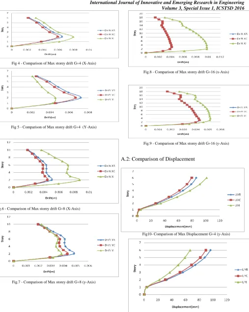
Fig 4 - Comparison of Max storey drift G+4 (X-Axis)
Fig 5 - Comparison of Max storey drift G+4 (Y-Axis)
Fig.6 - Comparison of Max storey drift G+8 (X-Axis)
Fig.7 - Comparison of Max storey drift G+8 (y-Axis)
Fig.8 - Comparison of Max storey drift G+16 (x-Axis)
Fig.9 - Comparison of Max storey drift G+16 (y-Axis)
A.2: Comparison of Displacement
Fig10- Comparison of Max Displacement G+4 (y-Axis)
Volume 3, Special Issue 1, ICSTSD 2016
Fig12- Comparison of Max Displacement G+8 (y-Axis)
Fig.13- Comparison of Max Displacement G+8 (y-Axis)
Fig.14- Comparison of Max Displacement G+16 (y-Axis)
Fig.15- Comparison of Max Displacement G+16 (y-Axis)
A.3: Comparison of Story Stiffness
Fig16- Comparison of Max Displacement G+16 (y-Axis)
Fig17- Comparison of Max Displacement G+16 (y-Axis)
A.4: Stability Coefficient
Story θXR θXC θXI
1 0.014162 0.013681 0.016919
2 0.099034 0.091105 0.119237
3 0.073458 0.067306 0.085592
4 0.052401 0.048031 0.061289
5 0.034416 0.031813 0.04102
6 0.016866 0.016043 0.021737 Table1-Stability coefficient in X-direction G+4
Story
θYR θYC θYI1
0.016442 0.015918 0.014724
2
0.107566 0.099486 0.068577
3
0.079595 0.073338 0.051274
4
0.056765 0.052333 0.037242
5
0.037678 0.035038 0.026279
6
0.01908
0.018244 0.015671
Volume 3, Special Issue 1, ICSTSD 2016
Story ΘXR ΘXC ΘXI
1 0.013719 0.013082 0.020339
2 0.102268 0.090477 0.174822
3 0.089984 0.079496 0.149371
4 0.078908 0.069841 0.13231
5 0.073093 0.065306 0.124068
6 0.065923 0.059393 0.112893
7 0.051795 0.046751 0.089558
8 0.037409 0.033848 0.06482
9 0.025722 0.023603 0.044241
10 0.014887 0.014245 0.024824 Table3-Stability coefficient in X-direction G+8
Story ΘYR ΘYC ΘYI
1 0.015802 0.015116 0.016348
2 0.111062 0.099075 0.089287
3 0.097834 0.087172 0.08073
4 0.085929 0.076735 0.073003
5 0.079319 0.071409 0.069122
6 0.072175 0.065495 0.064367
7 0.057626 0.052455 0.052647
8 0.041818 0.038192 0.039161
9 0.029088 0.026931 0.0281
10 0.017311 0.016655 0.017889 Table4-Stability coefficient in Y-direction G+8
Story ΘXR ΘXC ΘXI
1 0.0184893 0.0185551 0.0386315
2 0.0283423 0.0282397 0.0646559
3 0.0416216 0.0413479 0.0978355
4 0.0487004 0.0483418 0.1178415
5 0.0527108 0.0522979 0.1311216
6 0.0619395 0.0614043 0.1545155
7 0.0719055 0.0712652 0.1794331
8 0.0819978 0.0812589 0.2038556
9 0.0919792 0.0911442 0.2274076
10 0.1015999 0.100672 0.2506734
11 0.1108782 0.109861 0.2734665
12 0.1200396 0.1189351 0.2950774
13 0.1291522 0.1279603 0.3157649
14 0.1379362 0.1366529 0.3360135
15 0.145903 0.1445149 0.3546673
16 0.1517662 0.1502394 0.3675169
17 0.1461645 0.1446165 0.3667537
18 0.0231817 0.0231359 0.0391476
Table5-Stability coefficient in X-direction G+4
Story ΘYR ΘYC ΘYI
1 0.0229852 0.0230818 0.0310186
2 0.034205 0.0341174 0.0458421
3 0.0494802 0.0492031 0.0652094
4 0.0578835 0.0575283 0.0782352
5 0.062675 0.0622819 0.0871212
6 0.0732109 0.0726902 0.1008912
7 0.0847381 0.0841032 0.1153204
8 0.096262 0.0955122 0.1297581
9 0.1058917 0.1050296 0.1414771
10 0.112925 0.1119594 0.1497909
11 0.1188913 0.1178278 0.1568174
12 0.1259988 0.1248355 0.1644084
13 0.1347816 0.1335177 0.1731075
14 0.1441008 0.1427558 0.181459
15 0.1572583 0.1557993 0.1921253
16 0.1707041 0.1690804 0.2028383
17 0.1673279 0.1657408 0.1938972
18 0.0274914 0.027451 0.0323415 Table6-Stability coefficient in Y-direction G+16
IV.
Conclusion
From the study made and the results presented in the previous sections, the following important conclusions have been drawn within the preview of the buildings considered
1) Story drift in G+4 Building for Circular CFST column is observed to be 9% less than rectangular CFST column and 25% less than Steel Ishape columns in X-direction
2) Story Drift in G+8 for Circular CFST column is Observed to be 12% less than rectangular CFST and 49% less than Steel Ishape column in X-direction and 11% less in Y-direction
3) Story Drift in G+16 for Circular CFST column is observed to be 2% less than Rectangular CFST and 60% less than Steel I shape columns
4) Joint Displacement in G+4 for Circular CFST building is 8% less than RCFST and 22% less than Ishape column
Volume 3, Special Issue 1, ICSTSD 2016 6) Joint Displacement in G+16 for Circular CFST
building is 2% less than RCFST and 60% less than Ishape column
7) Story Stiffness of CCFST structure is more 4% more than RCFST structure and 21% more than steel I shape column structure
8) Stability Coefficient of Circular CFST is observed to be less than RCFST and Steel Ishape Column Structure by 5%
9) CFST buildings distribute loads more evenly than RCC
10) Composite structure (CFST) gives more ductility to the structure as compared to the Steel. which is best suited under the effect of lateral forces.
IX. REFERENCES
[1] [1] IS: 456, Code of practice for plain and reinforced concrete code of
practice, Bureau of Indian Standards, New Delhi, 2000.
[2] IS: 1893, Criteria for earthquake resistant design of structures - general
provisions for buildings, Part 1, Bureau of Indian Standards, New Delhi, 2002.
[3] IS: 875, “code of practice for design load (other than earthquake) for
buildings and structures” Bureau of Indian Standards, New Delhi, 2002.
[4] IS: 800, Code of practice for general construction in steel, Bureau of Indian Standards, New Delhi, 2007.
[5] IS: 11384, Code of practice for composite construction in structural
steel and concrete, Bureau of Indian Standards, New Delhi, 1985.
[6] Eurocode 4 (2004), Design of composite steel and concrete structures,Part1-1:General rules—structural rules for buildings. Brussels: EN1994-1-1, CEN.
[7] Shams M., Saadeghvaziri M.A., "State of the art of concrete-filled steel tubular columns", ACI Structural Journal 94 (5): 558-571 Sep-Oct 1997.
[8] Hajjar J.F., "Concrete-filled steel tube columns under earthquake loads", Prog. Struct.Engng Mater. 2: 72-81, 2000.
[9] Umesh P. Patil, “Analysis of g+15 rcc and composite structure having a soft storey at ground level by response spectrum and equivalent static methods using etabs 2013” IRJET, vol.2 issue 03 june 2015.
[10] IS 13920: 1993. “Indian Standard Code of the practice for the detailing of Reinforced Concrete Structures Subjected to Seismic Forces” Bureau of Indian Standards, New Delhi.
[11] Amish N. Shah 1, Dr. P.S. Pajgade(March -April 2013) “ Comparison Of R.C.C. And Composite Multistoried Buildings” International Journal Of Engineering Research And Applications (IJERA) ISSN: 2248-9622 Vol. 3, Issue 2, pp .534-539.