Correct the Path of A Robotic Medical Arm Using the Predictive Corrector and PID
Dr. Mohsen Khateb1 & Fatima Habqa2
1Associate Professor, Department of Industrial Automation, Faculty of Technical Engineering, Tartous University, Tartous, Syria. 2Master Student, Department of Industrial Automation, Faculty of Technical Engineering, Tartous University, Tartous, Syria.
Article Received: 19 September 2018 Article Accepted: 21 January 2019 Article Published: 16 April 2019
INTRODUCTION
The word Robot is called on mechanical machines capable of performing pre-programmed actions that show intelligent behavior, especially when simulating human behavior. The great technological progress and progress of these robots has been part of many fields, including the medical field. On the other hand, A needle in the medical center to occupy an important position, where these arms are used in the operations of injection of skin needles in the hard tissue and in blood donation centers for the withdrawal and transfer of blood, but all previous robotic arms need to accurately determine the path and error almost non-existent. Medical robotics is closed-circuit robots based on sensors and path analyzers. In this research, a four-degree robot robotic arm will be constructed, studied, simulated and programmed to correct its path and determine the position required for injection of the needles in the shoulder muscle. To put the end of the robot arm at any point within the 3D work space, but adding other joints will enable the robot to make more flexible and complex movements of only three degrees of freedom.
Problems:
Can the exact end position and direction of the medical robot be determined? Can any deviation from the desired path of the robotic arm be corrected?
Is it possible to predict the error caused by the control command before it occurs and avoid it? Can I reduce the nonlinear effects of servo drives?
A B S T R A C T
In this study, the problem of correcting the deviation of a four-step robotic arm and motor's joints is type servo dc to a specific position with the least possible error was suggested for the medical application. Injecting the needles in the shoulder muscle where we studied the time response of the robotic arm joints according to the desired quality indicators, Maximum acceleration, Stability time and static error, and focus on reducing static error as much as possible based on the PID and MPC. We designed the robotic arm and determined the dimensions of the pieces and the material manufactured by using a solid work program. Then transfer and export the form to the MATLAB2016 program and call it with the Mech_import instruction to obtain a model box diagram in the SIMLINK MATLAB environment to be modified to add the angular sensors and actuator from the _LIBRARY MECH library and the PID corrector and obtain the time response of the joints before and after the correction. And the values of the input angles were determined by a kinetic study of the robotic arm and modeled in MATLAB. As a result, the transport functions were derived from these curves and converted to state equations used to construct the predictive corrector model. On the other hand, and controlled by the Arduino-Mega2560, a software interface designed in Labview and five SERVO DC engines. The limit switch was used to limit the robot's working space and prevent the robot arm from hitting the coordinate platform. Finally, the practical results were compared with simulation results, accurate injection with near zero error and easy access to the injection position and stable movement where the MPC was more efficient and accurate than the PID.
Keywords: MPC Predictive Corrector, Static Error, Arduino Mega 2560, PID, a four-step robotic arm of freedom.
Research Objectives:
The research objectives can be summarized as follows:
Construct a correction algorithm for the serial robotic arm path used to inject the needles in the shoulder muscle by utilizing the MPC or PID prediction algorithms, eliminating the static state error, staying within the desired system constraints and achieving the desirable path of the robotic arm.
Minimize the nonlinear effects of servo drives by taking advantage of adding corrector to the front (direct) path..
Increase the efficiency of the control system by using the MPC corrector, which predicts the error of the control command before it occurs and avoids high accuracy and almost zero error.
First:
Kinematic study of a four - degrees- of - freedom of a robotic arm
We performed the kinetic study of the medical robotic arm, where the movement will be analyzed in a D-H method to study the forward movement and determine the coordinate sentence of each joint, and then conduct a study of the reverse motion geometrically.
Forward movement and determine the coordinate sentence of the robot arm
The study of the robot's forward motion determines the position and direction of the end of the arm and the joint variables, as each joint represents one degree of freedom and the position of each joint determined by its rotational angle . We represent the base of the cross-coordinate robot Figure (1-1) shows the coordinates of the robotic arm. [1]
Figure (1-1) the coordinates of the robotic arm.
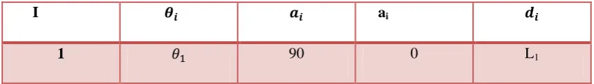
Table (1-1) shows the D-H parameters of the medical robot arm
I ai
2 0 L2 0
3 0 L3 0
4 0 L4 0
From these parameters we can find the coordinates of the position and the periodic matrix:
[
]
[
( )
]
Where the angle of direction of the end effect a given by the relationship
Study of the reverse movement of the robotic arm:
The calculation of the reverse movement depends on the final position of the moving end, where the angles of the joints are calculated by knowing the coordinates of the position.
Simulink & Modeling
In this chapter we have modeled and simulated the arm in the Matlab environment. We have built a forward movement model to calculate the elements of the matrix and the reverse motion model, using D-H and Robotic tools according to specific steps.
The Forward kinematic model in the Matlab environment:
Back to the movement analysis chapter and based on the D-H parameters, Table 1.3 The forward movement of the robotic arm is defined and the orientation angles are found in the Matlab environment, using Robotic tools according to the following steps:
Activate the tool Robotic tools.
Assignment of values for constants (L1, L2, L3, L4).
Enter the D-H parameters derived from Table (1-3) using the instruction L (i) = Link ([thi ai di a_i])
Determine the scope of the robot's operation by specifying the area of the junction angles. Determine the type of robot (serial robot).
Build forward motion robot kinematic
Rob.fkine([th1 th2 th3 th3])
Build the interface as described above.
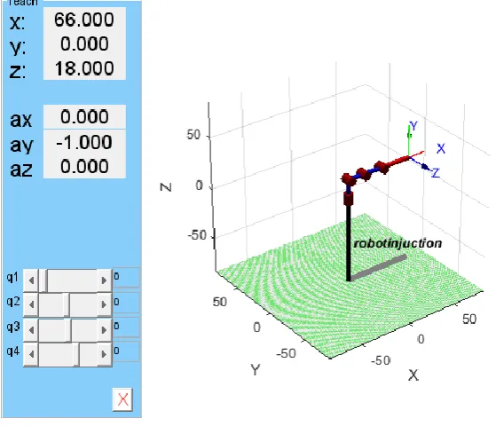
Calculate the position and direction of the moving end of the robot when moving the angle sliders.
An interface that facilitates the handling of the 4-DOF robotic arm, without getting into the complexities of mathematical equations, is shown in doubt (2-1), where we can calculate the coordinates of the impact position and steering angles by moving the angle sliders.
Reverse kinematic model in Matlab environment:
The reverse motion model is based on D-H and robotic tools. This model enables you to obtain the values of the joint angles when you enter the coordinates of the position of the moving end and its direction according to the following steps:
Activate the tool Robotic tools.
Assignment of values for constants (L1, L2, L3, L4).
Enter the D-H parameters derived from Table (1-3) using the instruction L (i) = Link ([thi ai di a_i])
Determine the scope of the robot's operation by specifying the area of the junction angles. Determine the type of robot (serial robot).
Determine the direction array values .qready Enter a transition matrix to the selected position Td = transl ([px py pz])
Build an inverse kinetic motion
q = ROb.ikine(Td, qready,[1 1 1 0 0 0]); Build the interface.
Enter the selected position from the command window.
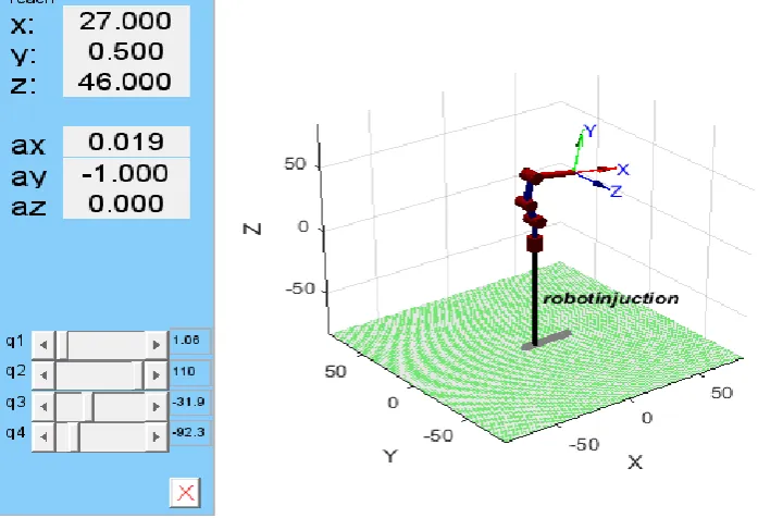
Figure (1-3) shows the reverse movement interface where the position is entered from the command window, calculating the angles of the joints.
Simulation of the robotic model in the Matlab environment Simulink:
A simulated robotic model was simulated so that we could get the time response of the joints before adding
and adding the correctors.
Firstly:
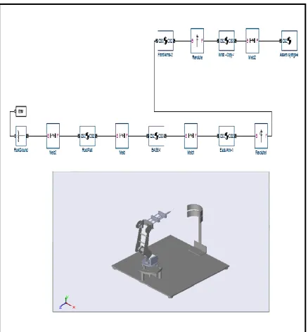
We started with the design of the robotic medical arm model on the solid work program consisting of base, shoulder, forearm, wrist, actuator and five servo motors. We then exported the model from solid work environment to Matlab using SIMSPACE MULTI-BODY FIRS GENERATION -PORT, The file was exported as a CAD Assembly file and exported to Matlab as an XML format based on the Simmechanic library.
Second:
The actuator joints and the sensor joints were added to each joint and the PID was added to the forward path. We applied the step signal, the values of the desired angles chosen according to the desired position, Injection of the desired needle, the form of the final form after masking:
Figure (1-5) the form of the final form after masking.
The PID constants were adjusted by manually calibrating the PID parameters in the continuous time to obtain the desired response, by experimenting with a model simulating the servo engine in a MATLAB environment. The following transfer of the servo motor is given in relation:
It is a second class transporter, given its general form:
Figure (1-6) shows the servo motor.
Table (2) shows the parameters of the engine under consideration that have been compensated in the servo motor diagram. Figure (1-7) shows the box diagram after inserting the engine parameters and adding the corrector.
Figure (1-7) the servo motor diagram after adding the debugger and entering the parameters. As mentioned above, most servo systems suffer from nonlinear effects in their behavior and affect their performance. Figure (1-8) shows the servo drive diagram after adding nonlinear parameters. [33]
Figure (1-8) the servo motor diagram with nonlinear parameters.
Building the predictive control model:
1. To construct the predictive control model, we need to represent the system as case parameters. Therefore, we represent the system with transport relays from the time response of each specification before debugging and then move to the case space (ie, from the chronological time of the servo engine):
The servo engine equations are in the case space, and the output is the angle (position) of the axis of rotationُ.
[ ̇ ̇ ̇ ] [
] [ ] [
]
[ ] [ ]
Or from a follow-up servo engine transfer:
Or we represent the system with transport relays from the time response of each specification before debugging from the simulation results (second class chronological
Beginning of:
• Maximum Override equation
δ
√ ⁄
(1-8)
• The peak arrival time
√ (1-9)
• Stability time
(1-10)
(1-11)
We create transport accessories for each base, shoulder, forearm and wrist.
2. Transfer the transfer to the state equations using the learning. tf2ss ()
3 .Transition to work in intermittent space.
Figure (1-10) Control model using the MPC corrector
5-5 Software interface and practical model:
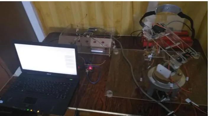
First, the robotic arm was designed in practice. It was controlled using the Arduino Mega 2560, the Labview, and the MG 995g stander except the micro servo continues. The end of the shoulder and shoulder blades were added to reduce the robot's work area and prevent it from hitting the coordinate platform. Figure (1-11) shows the practical design of the robotic arm.
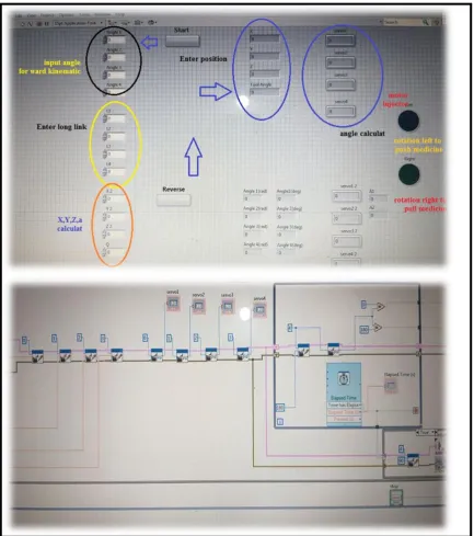
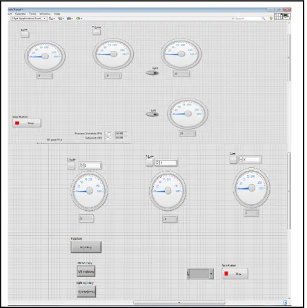
Second, the software interface was built using the Labview software. We initially loaded the Labview Interface for Arduino library and injected the file into the Arduino chip processor to achieve the connection between the Labview program and the Arduino chip. It should also be noted that the ID version affects the connection process. Using version 1.0.5 that is compatible with Labview 2017. Figure (1-12) shows the software interface used to test the practical model.
Figure (1-12) the software interface used to test the practical model.
Figure (1-13), (1-14), (1-15) shows the construction of the specific path to be taken by the robotic arm and the debugging rings of the interface.
Figure (1-14) PID debugger loop.
Discussion of results
Results of the study of the forward movement:
Table 3 presents the results of the practical experiments of the forward movement study, which were compared with theoretical study and modeling.
Table (3) Comparison of modeling results with the practical model.
2% 1.48%PID 0.65%MPC The position where the effective end
of the right
shoulder should reach. 3% 1.48%PID 0.65%MPC The position where the effective end
of the left
Table (3) shows the results of the reverse motion study, where the position and direction are introduced to obtain the corners of the joints.
Table (3) Results of reverse motion study.
Simulation results before and after adding corrector:
In this paragraph, we will review the results of the robotic arm simulation before and after the addition of the PID and MPC corrections. The angles that determine the robotic arm path of the specific position (injection position) were then identified and then corrected and then the results were compared:
Figure (1-6) shows the response of the robotic arm joints prior to correction within 30s and at angles (0,110, -31.9, -92.3). These are the angles of the wrist, forearm, shoulder and base that correspond to the coordinates (27,0,47) Injections, since these angles are the input of the model
.
Figure 1-16: Joint response before correction at 30 s.
6-4-1 Results of the PID Corrector:
Figure (1-17) shows the time response of these joints after the addition of the PID debugger, where we notice a clear improvement in the form of the time response, ie the PID debugger works well to eliminate the static state error. Low pass with the PID corrector
.
2-4-6MPC Debugger Results:
Predictive correction boxes were built using code in a Matlab environment, adjusting some of the input and output constraints and tuning the corrected box after obtaining the model according to the desired response. Figure (1-18) shows the time response of the robotic arm joints after adding the predictor and adjusting its parameters from time We observe that the input and output curves do not start from zero because the predictor controls the next time period when K = 0 starts the forecast horizon from K + 1 and we note that it reached the required value with a relatively small stability time A static status error Non-existent.
Figure (1-18) the temporal response of the robotic arm joints
The time response of the joints is studied when the signal reaches the stability. The quality indicators are calculated as follows:
•The stability time is determined when the output reaches a value between (0.98% - 1.02%) of the final value and remains within the range of these two values.
•Maximum Override:
Ascending time: the time to reach the top Mp for the first time.
The statistical error is calculated when a single signal input from equation:
Table (4) shows the system quality guides when the output reaches a value between 0.98% -102% of the final value after adding the corrector.
Table (4) Quality guides for medical robotic arm joints after adding the correctors. Quality guides for medical robotic arm joints after adding the PID
joint Static error Over shoot Ascension time Stability time Time principle 0S Joint 3 1.25% - 1.5s 1.5s joint2 1.1 % - 1s 1s joint1 1.2% - 2s 2s Joint0 - - - -
Quality guides for medical robotic arm joints after adding the MPC
joint Static error Over shoot Ascension time Stability time Time principle 1S Joint 3 0% 2% 2.2s 2.1s joint2 0% - 2s 2s joint1 0% - 2.2s 2.3s Joint0 - - - - Conclusion:
In this chapter, we present the results of the forward motion modeling and the inverse movement whose equations
were created in the theoretical section. The results are applied to simulate the robotic medical arm and compare it
with the results of the controlled model through the Labview program. And the measurement of the error at the
that both the predictor and the Correct the integrative differential ratio well-timed response to the joints of the
robotic arm well.
Conclusions and recommendations
Conclusions:
desired system constraints..
readings for the following moments, and this is shown by curves and differences with the reference value.
tor did not achieve a zero error in the practical model, so as not to include disturbances and
noise within the predictive model in this research.
REFERENCES
[1] A KRANTHI KUMAR, T. PITCHAIAH AND N. NARAYANA RAO (2017). "Robotic arm design and simulation usingmatlab/simulink for drones", international journal control theory and application, p43-54. [2] VIKAS KUMAWT, BHUVNECH KUMAR, BHUVNESH KUMAR ( 2013).
"PID Controller of Speed and Torque of Servo Motor Using MATLAB", International Journal on Recent and Innovation Trends in Computing and Communication, IJRITCC, 726-729.
[3]B.FADL, SH.BASEL, GH.IBRAHEEM (2017)."Applied Study of Controlling the Position of DC Motors Using Mat lab", AL BA'AS, 165-195.
[4] ABU – RASHED. HASAN (2011). "Model protective control of a dc motor", graduation project, volume: 101page.
[5] Hamdallah A. H. Alashqar (2017)." Modeling and High Precision Motion Control of 3 DOF Parallel Delta Robot Manipulator", A Thesis Submitted in Partial Fulfillment of the Requirements for the Degree of Master in Electrical Engineering, Gaza-Palestine, 1-82.
[6] GOGOI, UPASANA (Orissa 2013-2015)."Model Predictive Control of a Two link Flexible Manipulator", Department of Electrical Engineering National Institute of Technology, Rourkela, page 40-45.
[7] TEAM MATLAB (2016)." Real time DC Motor control using PID Controller".
[8] Ky M. Vu (2008)."ISO, MPC and PID: The Good, The Bad and The Ugly Discrete Controllers", AuLac Technologies Inc.
[10] Ivan Buzurovic,(4-8-2018). "Model of predictive control of the medical robotics system, Conference Paper", lectures in networks and systems, springer.
[11] Amin A. Mohammed (2015)." Kinematics Modeling of a 4-DOF Robotic Arm", International Conference on Control, Automation and Robotics.
[12] Mark W. Spong, Seth Hutchinson, and M. Vidyasagar (2004)." Industrial Robotics: Robot Dynamics and Control Second Edition", Germany.
[13]Dr. Ibrahim A Their (2016). "Design and implementation of a serial manipulator industrial robot with (4-DOF) electrically controlled", Tishreen University Journal for Research and Scientific Studies, 79-101. [14] Diebel, James (2006). "Representing Attitude: Eular Angles, Unit Quaternions, and Rotation", California, USA.
[15] Wolfram, ‘www.mathworld.wolfram.com/EularParameters.html’. [Online], [Accessed Jun 2015]. [17] E.MOUSA.HASSAN(1999). E.ABDALATEF.LOA , industrial control, dar shoaa.
[18] BENJAMIN C. KUO(2014). "automatic control system , prentice hall international",program studi teknik elektronika politeknik negeri batam.
[19] James Ron Leigh(2012) . Control Theory, "IET CONTROL ENGINEERING SERIES",IET. [20] S. Joe Qin, Thomas A. Badgwell (2002). "A survey of industrial model predictive control technology",ELSEVIER.
[21] J. A. ROSSITER(2005). "Model-Based Predictive Control", CRC Press.
[22]John ESPINOZA, Jorge BUELE,Esteban X. CASTELLANOS (2017). "Real-Time Implementation of Model Predictive Control in a Low-Cost Embedded Device".
[23]Michael Short, Fathi Abugchem (2017)." A Microcontroller-Based Adaptive Model Predictive Control Platform for Process Control Applications", This article is an open access article distributed under the terms and conditions of the Creative Commons Attribution (CC BY) license (http://creativecommons.org/licenses/by/4.0/). [24] Hanif Fauzan Prasetyo , Arief Syaichu Rohman (2017) ."Implementation of model predictive control using Algorithm-3 on Arduino Mega 2560 for speed control of BLDC motor", IEEE Conference Publication. [25] Peter Corke(February 2017). Resources for robotics education, http://petercorke.com/wordpress/ [26] Robot Kinematics, February 2017 http://www.wikipedia.com.
http://www.springer.com/cda/content/document/cda_downloaddocument/9789400705784-c2.pdf?SGWID=0-0-4 5-1338704-p174080776
[29] Kinematic and dynamic analysis of a robotic positioning arm, February 2017 .http://brl.ee.washington.edu/eprints/110/1/Th033.pdf
[30] Craig, J. J. (1989). "Introduction to Robotics Mechanics and Control", USA: Addison Wesley Publishing Company.
[31] W. W. Melek (2010). "ME 547: Robot Manipulators: Kinematics, Dynamics, and Control". Waterloo, ON, University of Waterloo.