245 Available online at www.ijiere.com
International Journal of Innovative and Emerging
Research in Engineering
e-ISSN: 2394 - 3343 e-ISSN: 2394 - 5494
Root Cause Analysis of Failures in the Testing of Concrete
Cubes by Compressive Testing Machine (CTM) (2)
Shreya Sule
1, Rahul Rao
1, Vikas Singh
1,Ajinkya Pradhan
1 1Affiliation: Rajiv Gandhi Institute of Technology, Mumbai, India.Guide: Prof. Amol Mangrulkar, Assistant Professor, Mechanical Engineering, Rajiv Gandhi Institute of
Technology
ABSTRACT:
The CTM is used in the concrete industry for testing the grades of the concrete produced. The entire infrastructure depends on the accuracy of the reading displayed by the CTM. The CTM can and has been found to display false readings. The causes to this can be a fault in CTM or the test specimen. The problems such as foundation of the machine, surface smoothness of the cube, misalignment of the cube, hydraulic oil seal, grade of oil and play of piston have been covered in this paper along with their solutions. This paper adds to our earlier work.
Keywords: Compressive Testing Machine, Foundation of the machine, Surface smoothness of the cube (test specimen), Misalignment of the cube, Seal of the hydraulic oil, Grade of oil and the Play of piston
I. AIMOFTHEPROJECT
Our aim is to identify the reason for display of false readings and try to provide corrective measures for the same. We are also going to study the major improvements made in this machine over the years.
II. INTRODUCTION[1]
Concrete is a material used for construction of infrastructure. It is a material which has a high compressive strength but a low tensile strength. Concrete is made by mixing a few other materials such as cement, water, aggregate, admixtures, fibers, polymers, reinforcements etc. in various proportions so as to obtain different grades of concrete.
III. LITERATURESURVEY[1]
Concrete is a composite material composed mainly of water, aggregate and cement. Often, additives and reinforcements are included in the mixture to achieve the desired physical properties of the finished material. When these ingredients are mixed together, they form a fluid mass that is easily molded into shape. Over time, the cement forms a hard matrix which binds the rest of the ingredients together into a durable stone-like material with many uses.
There are many types of concrete available, created by varying the proportions of the main ingredients below.
"Aggregate" consists of large chunks of material in a concrete mix, generally coarse gravel or crushed rocks such as limestone, or granite, along with finer materials such as sand.
Figure 1. Aggregates
246 Figure 2. Cement
Water is then mixed with this dry composite, which produces a semi-liquid that workers can shape (typically by pouring it into a form). The concrete solidifies and hardens through a chemical process called hydration. The water reacts with the cement, which bonds the other components together, creating a robust stone-like material. A lower water-to-cement ratio yields a stronger, more durable concrete, whereas more water gives a freer-flowing concrete with a higher slump.
Figure 3. Water to Cement Ratio Graph [2]
The above figure shows that validity range of water to cement ratio is very limited. Compressive strength is at peak, when water to cement ratio is low.
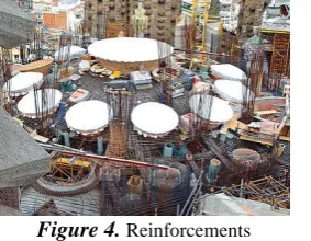
"Chemical admixtures" are added to achieve varied properties. These ingredients may speed or slow down the rate at which the concrete hardens, and impart many other useful properties including increased tensile strength and water resistance. "Reinforcements" are often added to concrete. Concrete can be formulated with high compressive strength, but always has lower tensile strength. For this reason it is usually reinforced with materials that are strong in tension (often steel).
Figure 4. Reinforcements
"Mineral admixtures" are also added to the concrete mix. The most conspicuous of these are fly ash, a by-product of coal-fired power plants, and silica fume, a by-product of industrial electric arc furnaces. The use of these materials in concrete reduces the amount of resources required, as the ash and fume act as a cement replacement. This displaces some cement production, an energetically expensive and environmentally problematic process, while reducing the amount of industrial waste that must be disposed of.
The mix design depends on the type of structure being built.
IV. CONCRETEPRODUCTION
247 In general usage, concrete plants come in two main types, ready mix plants and central mix plants. A ready mix plant mixes all the ingredients except water, while a central mix plant mixes all the ingredients including water. A central mix plant offers more accurate control of the concrete quality through better measurements of the amount of water added, but must be placed closer to the work site where the concrete will be used, since hydration begins at the plant.
A. Mixing concrete
Thorough mixing is essential for the production of uniform, high-quality concrete. For this reason equipment and methods should be capable of effectively mixing concrete materials containing the largest specified aggregate to produce uniform mixtures of the lowest slump practical for the work.
B. Workability
Workability is the ability of a fresh (plastic) concrete mix to fill the form/mold properly with the desired work (vibration) and without reducing the concrete's quality. Workability depends on water content, aggregate (shape and size distribution), cement content and age (level of hydration) and can be modified by adding chemical admixtures, like super plasticizer. Raising the water content or adding chemical admixtures increases concrete workability. Excessive water leads to increased bleeding (surface water) and/or segregation of aggregates(when the cement and aggregates start to separate), with the resulting concrete having reduced quality. The use of an aggregate with an undesirable gradation can result in a very harsh mix design with a very low slump, which cannot readily be made more workable by addition of reasonable amounts of water.
C. Curing
In all but the least critical applications, care must be taken to properly cure concrete, to achieve best strength and hardness. This happens after the concrete has been placed. Cement requires a moist, controlled environment to gain strength and harden fully. The cement paste hardens over time, initially setting and becoming rigid though very weak and gaining in strength in the weeks following. In around 4 weeks, typically over 90% of the final strength is reached, though strengthening may continue for decades.
V. PROPERTIES
Concrete has relatively high compressive strength, but much lower tensile strength. For this reason it is usually reinforced with materials that are strong in tension (often steel). The elasticity of concrete is relatively constant at low stress levels but starts decreasing at higher stress levels as matrix cracking develops. Concrete has a very low coefficient of thermal expansion and shrinks as it matures. All concrete structures crack to some extent, due to shrinkage and tension. Concrete that is subjected to long-duration forces is prone to creep.
VI. INDUSTRIALWORK[6]
Concrete is a material produced by mixing of the above materials in a ready-mix concrete plant. Concrete is a material that is in a matrix form. The matrix of concrete consists of two types of void spaces - one of 20mm diameter and the other of 10mm diameter. The smaller voids are filled with an element known as metal 1(aggregate) and the larger voids are filled with an element known as metal 2 (aggregate). Metal 1 and Metal 2 are both aggregates. Aggregates are added to form the matrix of concrete. The cement is added to this mixture to provide primary hydration. Cement also provides glue property. Cement, fly ash and water mixed together in desired proportion form glue which holds together the entire concrete matrix. Admixtures are provided for secondary hydration purpose. The admixtures are of two type- Chemical and Mineral. The chemical admixture consists of different types of water admixtures and the Mineral type admixture consists of fly ash, micro silica, meta kaolin.
Chemical admixtures are added to provide concrete with properties such as workability, durability, flow ability, strength gain (early strength gain or late strength gain), retention etc.
Cement also provides concrete with strength. It is mixed with water in a desired ratio. The best water to cement ratio is 0.24. Below this value the cement does not hydrate and if cement does not hydrate then it does not gain strength. [Refer fig.3]
VII. GRADESOFCONCRETEANDCTM Grades of concrete represent the compressive strength of concrete.
M10-M20 grades are the ordinary grade concretes or the low grade concrete. They contain more slurry and less aggregate. They are mostly used in the construction of roads etc.
M25-M60 grades are the standard grades of concrete. These are used for building of bridges, flyovers etc. Above M60 is the high grade concrete. They are used for construction of skyscrapers.
Higher the grade of concrete higher is their strength but also higher is their brittleness.
The numbers ahead of the letter M in the grades of concrete indicate the compressive strength of concrete in MPa. IS Code 516-1959 provides the methodology of testing the strength of concrete.
248 CTM stands for Compressive Testing Machine. This machine tests specimens of concrete to find their compressive strength. It is used in the construction industry, in concrete producing plants and at the construction sites - to test the concrete before use.
Compressive Testing Machine (CTM) is the most basic machine used for testing of concrete cubes in the construction industry. CTM measures and displays the compressive load on the concrete produced in kN to find the strength for the construction.
The CTM, however, has been observed to display false readings at times. This can be both hazardous and expensive. The following figure shows how the concrete cube being tested has to break during its test in the CTM.
Figure 5. Standard Breaking of Cube [7]
VIII. COMPRESSIVETESTINGMACHINE
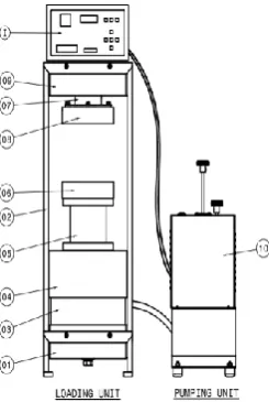
The CTM primarily available to us is shown in the schematic diagram below along with its specifications.
Figure 6. Schematic Diagram of CTM
Table 1. Parts of the CTM
Digital Compressive Testing Machine Capacity: 3000kN
Maximum clearance between platens: 400mm Maximum distance between side plates: 400mm Platen size: 320mm
Piston Diameter: 272.2mm
01:Base 06:Lower Platen 02:Support Plate 07:Spherical Seat 03:Jack 08:Upper Platen 04:Dust Cover 09:Cross Head
05:Spacers 10:Electrical Pumping Unit
249
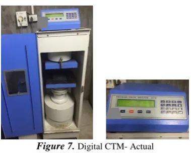
Figure 7. Digital CTM- Actual
Apart from using this machine, we were also given the opportunity to visit other plants that had various types of CTM with as well as without errors.
IX. TESTSPECIMEN [3]
Concrete is tested by molding it into two types of specimens. One type is a cube having dimensions 150mm×150mm×150mm and the other is a cylinder having Ø150mm and height 300mm.
The specimens are tested on the 3rd,7th and 28th day after molding. The strengths given on these days by the tested specimens are:
3rd Day: 50% of full strength 7th Day: 67% of full strength 28th Day: 100% of full strength
X. WORKING
Even if there are two types of specimens that can be used to carry out the testing, the most widely used option is the cube. The cube is placed at the center of the lower platen. The center of the lower platen is marked on it and there are concentric circles present around the center. The load is applied hydraulically- using hydraulic oil-on the piston. The pace rate is set electronically on the electric pumping unit. Then the machine is started. So the load is applied at a uniform rate of 140kg/sq. m/min. The piston then moves up at this uniform rate of loading. This causes the upward movement of the lower platen. The cube moves upward by a certain distance before making contact with the upper platen. Once the cube makes contact with the upper platen, which is fixed, the compressive load is gradually applied-pace loading- on the cube by the upward movement of the lower platen. The cube then starts taking the compressive load. The cube is loaded until it completely fails- three to four cracks. When the cube fails completely the electronic pumping unit stops automatically and the piston falls back and so does the lower platen. The final reading is shown by the digital load indicator in kN. This reading indicates the compressive load that can be taken by the concrete before it finally fails. From the compressive load reading obtained we can calculate the strength of concrete and compare it with the expected value of strength.
Figure 8. Breaking of the Cube
XI. THEDIFFERENTCOMPONENTSOFTHEMACHINETHATHAVEBEENCHANGEDDUETO
DISPLAYOFERROR
Through the Ages
Each component of the CTM that has changed through the years is highlighted below. Most of the components of CTM mentioned below are still in use but there are newer versions available like any other machines used by us.
A. Analogue Indicator
250 A solution to this problem is the digital load indicator used. It indicates the value of that load at which the specimen fails- with three to four cracks.
B. Manually Operated Pumping Unit
The load applied on the specimen has to be a pace load - gradually and uniformly applied load - to obtain a correct reading. This load is generally applied using a hydraulic arrangement. In a manually operated pumping unit, a hand lever is provided which has to be pumped to apply the load. Naturally manual pumping cannot result in pace loading of the specimen due to human errors, varying human strength and the human tendency of exhaustion.
The solution to this is an electrically operated pumping unit in which the rate of pace load can be adjusted and fixed for a particular testing.
C. Guides of the CTM
The guides are two or four rods that are equally placed on the CTM and connect the upper platen with the lower platen. The guides are usually threaded so that the upper and lower platen can move easily through them. But this can cause slipping of the platens due to wear of the guide threads. It can also result in inclination of the platens due to the same reason. This results in the indication of false readings by the machine.
Thus the guides have been replaced. The digital CTM does not have guides but instead has the upper platen fixed and the lower platen movable with the piston displacement. This eliminates the effect of the guides.
XII. EXISTINGERRORS Study of the Reasons for false readings [6]
The study of the reasons for the display of false readings by CTM is mentioned below:
A. FOUNDATION OF THE MACHINE
PROBLEM
It is absolutely necessary that the machine be kept on solid ground that is properly leveled. We found variations in the readings from the ideal expected value in a machine that was mounted on an aluminium sheet supported by some stones underneath it with a gap between the ground and the sheet.
Figure 9. CTM with improper foundation INVESTIGATION
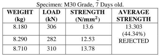
Thus we compared the readings taken on this machine with the readings taken on a machine with a solid foundation. The variations in the readings are given in the table below.
On the machine shown in the figure:
Table 2. Readings
Specimen: M30 Grade, 7 Days old. WEIGHT
(kg)
LOAD (kN)
STRENGTH
(N/𝒎𝒎𝟐)
AVERAGE STRENGTH
8.180 306 13.6 13.303
(44.34%) REJECTED 8.290 282 12.53
8.710 310 13.78
Note: STRENGTH=𝐹𝑂𝑅𝐶𝐸
𝐴𝑅𝐸𝐴, where force=load and area=150x150=22500𝑚𝑚
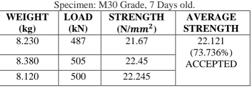
251 On a machine with a solid and proper foundation:
Table 3. Readings
Specimen: M30 Grade, 7 Days old. WEIGHT
(kg)
LOAD (kN)
STRENGTH
(N/𝒎𝒎𝟐)
AVERAGE STRENGTH
8.230 487 21.67 22.121
(73.736%) ACCEPTED 8.380 505 22.45
8.120 500 22.245
SOLUTION
Thus we conclude that the machine should be kept on a solid foundation else the load being applied to the test block is dissipated in some amount to the uneven or weak foundation as well. This can result in buckling of the foundation and also result in the variations in readings as shown above which may lead to rejection of the concrete due to the misconception produced by the false readings of the machine.
B. SURFACE SMOOTHNESS OF CUBE PROBLEM
Two surfaces of the cube come in contact with the upper and lower platen of the CTM. The load applied on the cube is purely a compressive axial load. The CTM gives a reading of the force (kN) at which the cube breaks. This value is then divided by the surface area to obtain the strength of the cube being tested. We already know the strength that we have manufactured the concrete at. With the testing our objective is to verify if the desired strength has been imparted to the concrete produced. Thus we know the standard of comparison. If the test values do not match the desired strength values we say that the concrete fails.
The surface area of the cube is 22500𝑚𝑚2.
Thus the obtained value of load indicated by the CTM is divided by this area to get the strength value of the concrete. Sometimes it so happens that the cube surface that is in contact with the platen is not smooth but has a few minute surface elevations (rough surface). In such a case the load instead of being applied over the entire surface is applied only at these elevations since the smooth platen will make contact with only the elevations. Due to the contact with elevations, the surface area of contact is reduced only to the sum of surface areas of each of the elevations on the cube surface. Generally it is not known that the cube surface is smooth or not. Thus the load value obtained is always divided by the entire surface area rather than the sum of elevation areas. Thus the actual surface area is always greater than the summation of the elevation surface area. When the load is divided by a greater value than the surface area that actually came in contact with the platen then the value of the strength obtained is lower than the expected value (ideal value).
INVESTIGATION
There was a particular batch of cubes that we tested that were not able to give the desired value of readings in spite of there being no problem with the CTM. That was when we discovered about the surface smoothness of the cube. The readings that were obtained are as follows:
Table 4. Readings
Specimen: M60 Grade, 3 Days old. WEIGHT
(kg)
LOAD (kN)
STRENGTH
(N/𝒎𝒎𝟐)
AVERAGE STRENGTH 8.540 507 22.533 22.917
(38.19%) REJECTED 8.920 550 24.44
8.780 490 21.778
Table 5. Readings
Specimen: M60 Grade, 7 Days old. WEIGHT
(kg)
LOAD (kN)
STRENGTH
(N/𝒎𝒎𝟐)
AVERAGE STRENGTH
8.110 730 32.44 32.38
(53.96%) REJECTED 8.310 713 31.68
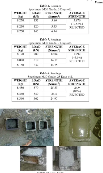
252 Table 6. Readings
Specimen: M30 Grade, 3 Days old. WEIGHT
(kg)
LOAD (kN)
STRENGTH
(N/𝒎𝒎𝟐)
AVERAGE STRENGTH
8.270 132 5.86 5.876
(19.58%) REJECTED 8.230 120 5.33
8.260 145 6.44
Table 7. Readings
Specimen: M30 Grade, 7 Days old. WEIGHT
(kg)
LOAD (kN)
STRENGTH
(N/𝒎𝒎𝟐)
AVERAGE STRENGTH
8.120 289 12.84 13.92
(46.6%) REJECTED 8.020 319 14.17
8.180 332 14.75
Table 8. Readings
Specimen: M30 Grade, 28 Days old. WEIGHT
(kg)
LOAD (kN)
STRENGTH
(N/𝒎𝒎𝟐)
AVERAGE STRENGTH
8.480 570 25.33 24.9
(83%) REJECTED 8.460 549 24.4
8.390 562 24.97
Figure 10. Cube Molds
On investigating the cause of the rough surface we found that the cube mold was improper. The inner surface of the mold was rough and spoilt due to frequent use. This led to a rough cube surface.
Figure 11. Spoilt Cube Mold
253
Figure 12. Actual Figure 13. Ideal
Figure 14. Cube mold disassembled
Figure 15. Improper breaking of the cubes being tested
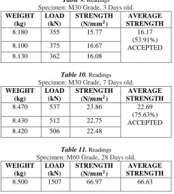
SOLUTION
The best and most obvious solution was to change the cube mold and get a new one. The readings using a new cube mold were as follows:
Table 9. Readings
Specimen: M30 Grade, 3 Days old. WEIGHT
(kg)
LOAD (kN)
STRENGTH
(N/𝒎𝒎𝟐)
AVERAGE STRENGTH
8.180 355 15.77 16.17
(53.91%) ACCEPTED 8.100 375 16.67
8.130 362 16.08
Table 10. Readings
Specimen: M30 Grade, 7 Days old. WEIGHT
(kg)
LOAD (kN)
STRENGTH
(N/𝒎𝒎𝟐)
AVERAGE STRENGTH
8.470 537 23.86 22.69
(75.63%) ACCEPTED 8.430 512 22.75
8.420 506 22.48
Table 11. Readings
Specimen: M60 Grade, 28 Days old. WEIGHT
(kg)
LOAD (kN)
STRENGTH
(N/𝒎𝒎𝟐)
254 8.490 1490 66.22 (111.05%)
ACCEPTED 8.350 1501 66.71
We also tried a few ways to mend the problem. We tried doing grinding and filing on the cube surface to make it smooth. The cube surface can also be rubbed using a sand paper to make it smoother for testing.
We learnt that grinding can be done to some extent on the lower grades of concrete from M10 to M20. We can also initially use sand paper for smoothing the lower grade concrete and then use the grinding machine. These grades of concrete contain a higher amount of slurry so it can be ground easily as grinding would primarily remove this slurry. However, the higher grades of concrete above M20 cannot be ground to get the desired results. Concrete is a material that is in matrix form with aggregates and ad-mixtures forming an integral part of the matrix. If the higher grades of concrete are ground then the matrix of concrete is disturbed and the aggregates and ad-mixtures which are involved in the matrix formation come loose and fall off. This destroys the entire structure of concrete. Also during grinding the machine vibrates and so does your hand, thus a complete horizontal surface is hard to achieve.
Thus we can say that it is best to replace the mold to obtain a desired smooth surface for testing of the concrete cube. Also when the cube is molded the top surface of the cube is open and is manually leveled. This can cause the surface to be rough. Since this is only one surface, we do not make use of this surface while testing to avoid errors in the readings.
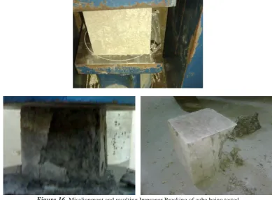
C. MISALIGNMENT OF CUBE
PROBLEM
The load that is applied on the cube is due to the upward movement of the lower platen is influenced by the movement of the piston under hydraulic pressure. The upper platen is fixed and only the lower platen moves. The cube has to be placed at the center of the lower platen so that when it moves up and makes contact with the upper platen, the center of the cube and both the platens are along the same vertical line. Only in such a scenario, the load that is applied over the cube will be uniform. If the cube is not placed at the exact center of the platens then the loading will not be uniform and may be a combination of axial load and moment.
Figure 16. Misalignment and resulting Improper Breaking of cube being tested INVESTIGATION
The variation in readings when the cube is misaligned and when it is placed at the center is shown below: Table 12. Readings
Specimen: M30 Grade, 7 Days old. WEIGHT
(kg)
LOAD (kN)
STRENGTH
(N/𝒎𝒎𝟐)
AVERAGE STRENGTH
8.190 300 13.33 13.36
(44.53%) REJECTED 8.230 297 13.2
255 Table 13. Readings
Specimen: M60 Grade, 7 Days old. WEIGHT
(kg)
LOAD (kN)
STRENGTH
(N/𝒎𝒎𝟐)
AVERAGE STRENGTH
8.300 512 22.75 22.66
(37.77%) REJECTED 8.350 523 23.24
8.270 495 22
Table 14. Readings
Specimen: M30 Grade, 28 Days old. WEIGHT
(kg)
LOAD (kN)
STRENGTH
(N/𝒎𝒎𝟐)
AVERAGE STRENGTH
8.490 540 24 25.38
(84.62%) REJECTED 8.430 578 25.68
8.410 596 26.48
Actual Expected Value: >= 50% for 3 Days >= 67% for 7 Days
>= 100% for 28 Days [Ref.3]
SOLUTION
Thus we can see that it is necessary to place the cube at the exact center of the platen.
The center of the platen is already marked on it by the manufacturer by a set of concentric circles.
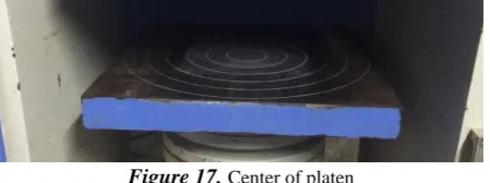
Figure 17. Center of platen
Even though the center of the platen is already marked, the operator placing the cube does not always place the cube at the center of the platen. This is a common problem found in plants and industries where the negligent operator just does an assigned work for its completion and not for its results. Thus the issue at hand is to find the center of the cube and place the cube at the center of the platen.
a. Solution 1
i. Laser Alignment and Position Sensing Technology [4]
Figure 17. Laser and Positioning Devices
ON-TRAK Photonics Corporation is a leading manufacturer of laser alignment measurement equipment based on a position sensing detector (PSD) technology.
Laser Alignment Capabilities include:
The ability for measurement of X,Y deviations from a reference line over distances of up to 300 feet, with a clear, digital accuracy resolution up to 0.0001”
The ability for measurement of a rotating plane of laser light over distances of 100 feet, with a clear, digitally accurate resolution up to 0.0001”
Options for computerized control and data recording of the laser alignment data received
Real time operation and feedback for the quick re-engineering adjustment to be made in manufacturing environments
256
ON-TRAK Photonics’ laser alignment technology has long been used in Boeing’s aircraft manufacturing process, in applications such as wing assembly, fuselage assembly, stow bin alignment, hinge alignment and seat track alignment. Of course, in this situation accuracy is critical, and laser alignment allows incredibly precise measurements over long distances.
ii. Position Sensors [5]
Contact positioning sensors- GT2 series
Reflective positioning sensors- GV series, IA series, IL series and LB series
GV Series IA Series IL Series Ultrasonic sensors- FW series
The above information represents various laser and sensor positioning systems that can be used effectively for the correct positioning of the cube on the platen.
b. Solution 2
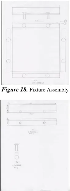
Using a fixture can also be a possible solution to the misalignment of the cube. The fixture that we designed and suggested is:
Figure 18. Fixture Assembly
257 There would be two of these fixtures used- one each on the upper and lower platen. We have to fix the fixtures on the platens by taking measurements. Also, in order to attach the fixtures to the platens we will have to drill holes in the platens. The disadvantage regarding this can be that the platens with have to be drilled.
But using a fixture will ensure that the cube is in the right position and that it is held there firmly.
c. Solution 3
This is one of the simplest and cheapest solutions to the problem of cube misalignment. With the help of a measuring instrument such as a scale and by using a marker we can draw the outline of the cube- which has standard dimensions only- on the lower platen. The operator can then place the cube in/on the outline drawn and proceed with the testing.
Advantages:
Simple solution Cheap and economical Quickly applicable Disadvantages:
Lot of human errors-during drawing of the outline, placing of the cube in/on the outline, tolerances of the cube.
D. SEAL OF THE HYDRAULIC OIL PROBLEM
The lower platen is lifted up by the upward movement of the piston. The piston is operated by pressure that is applied hydraulically with the help of hydraulic oil. The pressure is set and given by the electrical pumping unit shown in fig. 6. The piston is placed in the closed compartment below the lower platen and is sometimes visible in certain machines depending upon the type of CTM being used. The hydraulic oil surrounds the piston in the lower compartment but as the piston moves upward during the upward stroke, the piston comes out of the lower compartment whereas the oil does not leave the compartment. This is due to a rubber seal that is present around the piston that keeps the oil from leaking out and thus maintains the desired pressure for the piston to move upward. Also, if the oil leaks out, there will be friction between the piston ad the lower compartment and this friction would restrict the movement of the piston upward. So the load that is applied by the machine on the cube is then split partway on the cube and partway on overcoming friction. This leads to the display of false readings by the CTM in the testing of the concrete specimen.
258 INVESTIGATION
In this case the readings are not less than the expected value but are more than it. However, they are not just more but they are abnormally more than the expected values. This also is an indicator of faulty operation. If the concrete produced does not have high strength but is displayed so due to errors of the CTM then due to this reading the faulty concrete may be approved and used in buildings and other constructions. But since the concrete is actually faulty it will not be able to take the load and will collapse. The readings taken on this machine are given below:
Table 15. Readings
Specimen: M30 Grade, 28 Days old. WEIGHT
(kg)
LOAD (kN)
STRENGTH
(N/𝒎𝒎𝟐)
AVERAGE STRENGTH
8.490 900 40.00 40.07
(133.57%) 8.430 892 39.644
8.410 913 40.577
Table 16. Readings
Specimen: M60 Grade, 28 Days old. WEIGHT
(kg)
LOAD (kN)
STRENGTH
(N/𝒎𝒎𝟐)
AVERAGE STRENGTH 8.490 1891 84.04 83.316
(138.86%) 8.430 1848 82.13
8.410 1885 83.778
Table 17. Readings
Specimen: M60 Grade, 3 Days old. WEIGHT
(kg)
LOAD (kN)
STRENGTH
(N/𝒎𝒎𝟐)
AVERAGE STRENGTH 8.490 1019 45.288 50.205
(83.67%) 8.430 1232 54.75
8.410 1138 50.577
SOLUTION
Thus a rectification of this problem is essential. A solution to the above problem is that the machine needs to be inspected periodically for any such damage. The seal has to be replaced as soon as found damaged. There is no other alternative than the replacement of the seal.
Figure 21. Changing the Broken Seal
E. GRADE OF THE OIL PROBLEM
259 used than the specified one then the CTM is not able to function properly. In fact the CTM is not able to provide any pressure at all to the piston so thus the piston does not get lifted up or can fall back in mid operation.
This does not only occur due to use of low grade oil but can also occur due to wear and tear. If the CTM is used for a long period without the replacement of the oil then the oil starts degrading. Again such oil is unable to provide any pressure to the piston and the CTM then would not be able to operate.
Figure 22. Degraded Oil
SOLUTION
Solution to this problem is similar to the previous one and involves the timely inspection of the CTM. However, this problem is easily detected in the CTM, even if no inspection is done, as the piston is clearly not able to take the load and keeps falling back down. This is an indicator of the degraded oil or the misuse of oil. In such a case the oil needs to be immediately replaced to facilitate the proper functioning of the CTM.
F. PLAY OF THE PISTON
There is a gap between the piston and its housing so as to avoid the rubbing of the piston on the inner surface of the housing. But however, due to this gap the piston tends to have a rocking movement in the horizontal plane. This can in turn cause the undue movement of the lower platen and hence affect the readings.
A way to avoid this is to install guides that pass through the piston and to the ground so that the piston can easily glide along these guides without any horizontal movement.
XIII. CONCLUSION
Thus we can say that it is essential to regularly test the accuracy of the CTM. In case of any discrepancies, it is advisable to re-calibrate the machine so as to avoid hazards. Also, one or more of the solutions suggested above can be taken into consideration, in the scenario where re-calibration is not possible.
XIV. FUTURESCOPE
This paper covers only a few problems and their corresponding solutions, of the CTM. But, the CTM can show false reading on many other occasions and in various conditions. These errors have yet to be studied and stated.
ACKNOWLEDMENT
We are grateful to our guide Prof. Amol Mangrulkar, for guiding, supporting and helping us throughout the course of our project.
We are also thankful to the team at Navdeep Construction Co. for letting us work on and complete our project in their plant and office premises.
REFERENCES [1] Wikipedia-concrete: http://en.wikipedia.org/wiki/Concrete
[2] EngineeringIntro-concrete/concrete-strength/water-to-cement-ratio [3] IS Codes.
[4] ON-TRAK Photonics, Inc.: http://www.on-trak.com/theory.html [5] Keyence, America.:http://www.keyence.com/products/sensor/ [6] Industrial Work- Navdeep Construction Co.