Original Article
The Effects of Different Miniscrew Thread Designs and Force Directions on
Stress Distribution by 3-dimensional Finite Element Analysis
Hamidreza Fattahi a, Shabnam Ajami a, Ali Nabavizadeh Rafsanjani b
a
Orthodontic Research Center, Dept. of Orthodontics, School of Dentistry, Shiraz University of Medical Sciences, Shiraz, Iran.
b Dept. of Orthodontics, School of Dentistry, Rafsanjan University of Medical Sciences, Rafsanjan, Iran.
KEY WORDS
Miniscrew;
Thread;
Finite Element Analysis;
Force Direction
Received November 2014; Received in revised form May 2015; Accepted July 2015;
ABSTRACT
Statement of the Problem: The use of miniscrew as an absolute anchorage device in clinical orthodontics is growing increasingly. Many attempts have been made to
reduce the size, to improve the design, and to increase the stability of miniscrew.
Purpose: The purpose of this study was to determine the effects of different thread
shapes and force directions of orthodontic miniscrew on stress distribution in the
supporting bone structure.
Materials and Method: A three-dimensional finite element analysis was used. A 200-cN force in three angles (0°, 45°, and 90°) was applied on the head of the
miniscrew. The stress distribution between twelve thread shapes was investigated
as categorized in four main groups; buttress, reverse buttress, square, and V-shape.
Results: Stress distribution was not significantly different among different thread shapes. The maximum amount of bone stress at force angles 0°, 45°, and 90° were
38.90, 30.57 and 6.62 MPa, respectively. Analyzing the von Mises stress values
showed that in all models, the maximum stress was concentrated on the lowest
diameter of the shank, especially the part that was in the soft tissue and cervical
cortical bone regions.
Conclusion: There was no relation between thread shapes and von Mises stress distribution in the bone; however, different force angles could affect the von Mises
stress in the bone and miniscrew.
Corresponding Author: Ajami Sh., Orthodontic Research Center, Dept. of Orthodontics, School of Dentistry, Shiraz University of Medical Sciences, Shiraz, Iran. Tel.: +98-71-36263193-4
Fax: +98-71-36270325 Email: dr.ajami.sh@gmail.com
Cite this article as: Fattahi H., Ajami Sh., Nabavizadeh Rafsanjani A. The Effects of Different Miniscrew Thread Designs and Force Directions on Stress Distribution by 3-dimensional Finite Element Analysis. Dent Shiraz Univ Med Sci., December 2015; 16(4): 341-348.
Introduction
Orthodontic miniscrews have revolutionized
orthodon-tic treatment plans. Nowadays, the use of miniscrew as
an absolute anchorage in clinical orthodontics is
grow-ing increasgrow-ingly. Some reasons for this growth include
easy insertion and removal of the miniscrew without
irreversible changes, [1] immediate loading, [2] low
cost of the instruments, and shorter duration of the
treatment. [3-4]
One of the requirements of immediate loading is
primary stability [5-7] which is influenced by several
factors including the design of the miniscrew, implant
size, insertion angle, insertion torque, force angle, and
the amount of applied force. [8] Design of the
minis-crew is characterized by some factors such as the
length and diameter of the miniscrew, thread shape,
pitch, and depth. [9] Different thread shapes have been
introduced, the basic forms of which are square,
V-shape, buttress and reverse buttress. [8] Attempts to
maximize the stability while minimizing the placement
torque has led to the development of smaller
minis-crews, which would broaden their clinical use.
Many studies on the design of orthodontic
have been conducted. [5, 8-9] Gracco et al. conducted
an in vitro study to evaluate the effect of thread shapes
on the pullout strength of the miniscrews. They
de-signed four types of thread named as buttress, 75 joint
profiles, rounded, and trapezoidal. They concluded
that the thread design influenced the resistance to
pullout and consequently the primary stability of
or-thodontic miniscrews. [7] Migliorati et al. used thread
shape factor to determine the relationships between
geometrical characteristics and mechanical properties
of the temporary anchorage devices. Their results
showed that maximum insertion torque and load
val-ues of the pull-out test were statistically related to the
depth and shape of the thread of the screw. [11]
Duai-bis et al. showed that different thread shapes had no
effect on the stresses around the cortical bone. [12]
However, some studies, carried out on dental implants,
have indicated that a key factor for the success or
fail-ure of dental implants would be the type and the
amount of the bone stress. [8, 13] Kong et al. designed
a finite element study to determine the optimal thread
shape for an experimental cylinder dental implant.
Twelve 3D models of dental implants with different
thread shapes were investigated. They concluded that
some of the thread shapes had better stress
distribu-tion. [14] Liu et al. showed that the direction of
ortho-dontic forces had no significant effect on the cortical
bone stress. However some other studies did not
sup-port this finding. [15-16] So there is a controversy over
the impact of thread shapes on the bone stress and
sta-bility. Regarding this gap in literature, we decided to
carry out a study to determine the effect of different
thread shapes and force angles on stress distribution of
bone and miniscrew. In our study, finite element
anal-ysis was used to evaluate the effect of different
minis-crew thread shapes and load angles on stress
distribu-tion around miniscrew and supporting bone.
Materials and Method
A three dimensional (3D) geometric model of a
minis-crew as a bone anchorage was created with the
com-puter aided design software SolidWorks2013 (Figure
1). Cortical and cancellous bones were modeled. A
cuboid of 20mm long, 20mm wide and 10mm thick
was modeled, considering the upper 1.5 mm as soft
tissue, the upper 2 mm was considered as cortical bone
and the rest as cancellous bone. The material
proper-ties of the elements in finite element are shown in
Ta-ble 1. [10]
Table 1: Properties of the material used in this investigation
Young’s modulus (GPa)
Poisson’s ratio
Reference
Pure titanium 110 0.33 10 Cortical bone 14.7 0.30 10 Cancellousbone 1.3 0.30 10
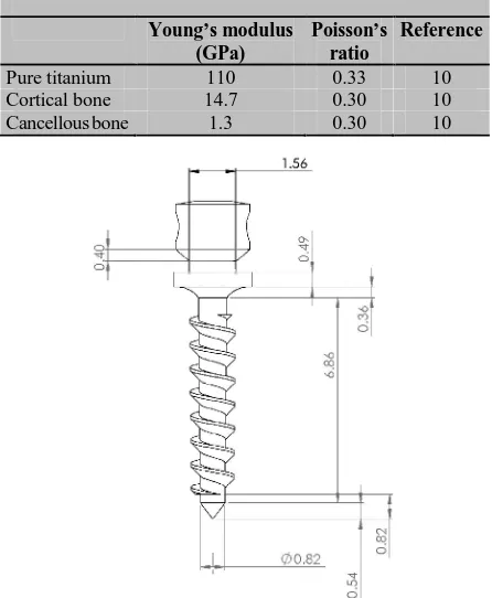
Figure 1: Detailed dimensions of the miniscrew
The characteristics of the miniscrew based on the
model designed by Singh et al. using microscope tool
mark were as fallowing; [9] the total length of
minis-crew was 10.62 mm and the length of the threaded
shank was 6.84 mm. The tip was 0.54 mm long. Shank
of the miniscrew had tapering with the diameter of
0.95mm in the largest part without considering the
thread width and 0.82 mm in the smallest diameter
.The part of miniscrew outside the bone was 3.22 mm.
The largest diameter of the head was 2.48 mm and the
smallest part was 1.56 mm. The thread pitch was
con-sidered 0.8 mm and was arranged on the shank in a
spiral pattern. The miniscrew was inserted at the right
angle in the bone.
For better understanding of the stress
distribu-tion, the twelve different thread configurations were
categorized in four main groups: buttress (B-1, B-2,
and B-3), reverse buttress (R-1, R-2, and R-3), square
(S-1, S-2 and S-3), and V-shape (V-1, V-2 and V-3).
Thread depth (the distance between shank and the
thread tip) was 0.3mm in all configurations. The
V-Figure 2: Schematic representation of the miniscrew thread shapes: (S=square; V=V-shaped; B=buttress; R=reverse buttress)
shape groups was the angle between the two wings of
the thread. The square group was divided by the thread
width. The details of these designs are showed in
Fig-ure 2.
All the materials in this modeling were
consid-ered homogeneous which means the elastic properties
were all the same at all points in the material, isotropic
which means the same elastic properties existed in all
directions at any point of the material, and linearly
elastic which was an acceptable assumption due to the
small deformation occurred during loading. Hence,
there was a linear relation between stress and strain.
Bone and miniscrew had a finite slip and the friction
coefficient equal to 0.2, as suggested by Lombardo et
al. [17] Finite element model was constructed and
au-tomatically meshed with 10 node tetrahedral solid
el-ements (solid 186 and solid 187) by using ANSYS
Workbench Version 14 (Southpointe; 275 Technology
Drive, Canonsburg PA 15317, USA).In all models, the
number of elements varied between 850000 to
1200000 due to the difference in the thread shapes of
the miniscrew. In all cases, the maximum skewness of
the worst element was <0.9 and minimum orthogonal
quality of the worst element was >0.15.
For stimulating the pull force on the head of
miniscrew, a 200-cN force was applied on the head of
the miniscrew in 3 directions (0°, 45° and 90°). The
90° force angle was parallel to the cortical surface,
perpendicular to the long axis of the miniscrew, and
the 0° force angle was along the long axis of the
miniscrew in positive direction of y axis (extrusive).
The 45° force angle was between 0° and 90° force
angles. Finally, 36 different modes were simulated.
The effects of miniscrew thread design and different
force directions (0°, 45°, and 90°) on the stress
distri-bution were investigated.
The results of finite element analysis were expressed
as stress distribution in the structures. The stresses
included tensile, compressive and shear which can
interpret as von Mises stress or equivalent stress. Von
Mises stress is widely used by designers to make sure
whether their design withstands the given loaded con-
dition. [8,18] Thecalculatednumerical data were
shift-ed into color band diagram for better understanding
Table 2: Maximum cortical equivalent stress under 200-cN force ( MPa)
B1 B2 B3 R1 R2 R3 S1 S2 S3 V1 V2 V3
Force angle 0° 35.87 36.38 38.90 36.58 35.87 36.81 36.87 36.40 37.26 36.56 38.45 37.31 Force angle 45° 26.79 29.06 27.55 26.50 30.37 29.11 29.42 29.58 30.52 28.07 30.23 30.57 Force angle 90° 6.02 6.00 6.62 6.12 6.51 6.05 6.43 6.12 6.35 5.74 6.41 6.24
B: Buttress thread shape, R: Reverse buttress thread shape, S: Square thread shape, V: V-shape thread shape
of the mechanical phenomena in models. The stress
values were indicated in mega Pascal (MPa) or
New-ton per square millimeter. Deformation due to
horizon-tal loading predominantly occurred in the x-axis
direc-tion and the values were reported in millimeters.
Results
Bone stress distribution
Generally, the amount of stress for all force directions
(0°, 45°, and 90°) and in all thread shapes was greater
in the cortical bone than the cancellous bone. The
greatest amount of stress in cortical bone was at the
entrance of the miniscrew to the bone; the stress levels
reduced gradually toward the tip of the miniscrew
(Figure 3).
At the 0° force angle, the peak von Mises stress
of the cortical bone ranged between 35.87 to 38.90
MPa with the minimum amount for the buttress 1(B-1)
and reverse buttress 2(R-2) thread shapes and the
max-imum amount for buttress 3 (B-3) thread shape.
How-ever, when the angle was increased by 45 degrees, the
peak von Mises stress decreased to 26.5-30.57 MPa,
the lowest amount of which was observed in reverse
buttress 1(B-1) and the greatest in square 3(S-3) and
V-shape 3(V-3) thread shapes. At 90° force angle, the
peak von Mises stress declined significantly and the
lowest stress was related to V-shape 1(V-1) (5.74
MPa) and the highest was related to buttress 3 (B-3)
thread shape (6.62 MPa). (Table 2) Table 3 shows the
maximum shear stress.
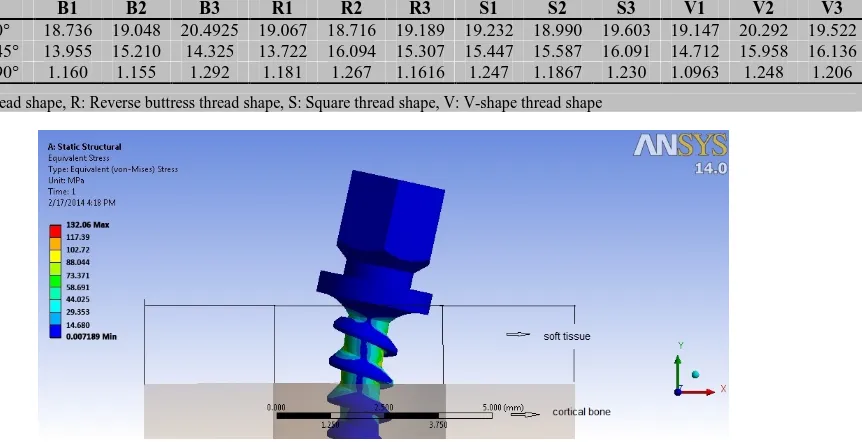
Miniscrew stress distribution
The peak von Mises stress in the miniscrew was at the
smallest diameter of the shank, especially in the part
inserted in the soft tissue. Generally, toward the tip of
miniscrew, this value was decreased. For the part of
the miniscrew located within the cortical bone, the
greatest amount of stress was in the narrowest part of
the shank (Figure 4).
Applying the 0° force angle, the peak von Mises
stress of the miniscrew was ranged from 122.62MPa to
132.06 MPa, the lowest and greatest amount were for
V-shape 1(V-1) thread shape and reverse buttress 1
(R-1) thread shape, respectively. However, when the
angle of force increased to 45o, the peak von Mises str-
Table 3: Maximum cortical shear stress under 200-cN force ( MPa)
B1 B2 B3 R1 R2 R3 S1 S2 S3 V1 V2 V3
Force angle 0° 18.736 19.048 20.4925 19.067 18.716 19.189 19.232 18.990 19.603 19.147 20.292 19.522 Force angle 45° 13.955 15.210 14.325 13.722 16.094 15.307 15.447 15.587 16.091 14.712 15.958 16.136 Force angle 90° 1.160 1.155 1.292 1.181 1.267 1.1616 1.247 1.1867 1.230 1.0963 1.248 1.206
B: Buttress thread shape, R: Reverse buttress thread shape, S: Square thread shape, V: V-shape thread shape
Table 4: Maximum miniscrew equivalent stress under 200-cN force (MPa)
B1 B2 B3 R1 R2 R3 S1 S2 S3 V1 V2 V3
Force angle 0° 130.58 131.66 131.19 132.06 130.58 132.00 122.85 122.87 125.04 122.62 126.91 124.50 Force angle 45° 107.54 108.40 104.07 108.63 105.06 108.72 93.10 99.01 103.01 100.60 100.15 99.91 Force angle 90° 22.56 22.78 22.58 22.64 22.57 22.85 21.49 21.27 21.54 20.78 21.43 21.84
B: Buttress thread shape, R: Reverse buttress thread shape, S: Square thread shape, V: V-shape thread shape
ess decreased with lowest amount for square 1(S-1)
thread shape (93.10 MPa) and the greatest for reverse
buttress 3(R-3) thread shape (108.73 MPa). At 90°
force angle, the peak von Mises stress declined
signifi-cantly. The range was from 20.78 MPa to 22.85 MPa,
with the lowest amount for V-shape 1 thread shape and
the largest for reverse buttress 3 (R-3) thread shapes.
(Table 4)
Deformation
The maximum deformation in all groups was at the
head of the miniscrew, whereas to the tip of the
minis-crew, this value was reduced. (Figure 5) With the 0°
force of angle loading, the maximum value was for
square 1(S-1) thread shape (0.0116 mm) and the
min-imum was for V-shape 2 (V-2) thread shape (0.0154
mm). At the 45° force angle, the result showed the
range was between 0.0070 mm and 0.0109 mm. The
largest value was for square 1(S-1) thread shape and
the minimum was for V- shape 1(V-1) thread shape
(Table 5).
Discussion
This study was conducted to evaluate the effects of
various thread shapes and force directions on the stress
distribution in different parts engaged in the process of
loading.
The purpose of having threads on the miniscrew
is to enhance the initial contact and surface area, which
will optimize the stress distribution in the contact areas
between the bone and the miniscrew. [8, 19] Various
forms of screw thread can have different impacts on
the initial stability. Some of the thread forms
intro-duced for dental implants are the square, V-shape, and
buttress. The V-shape thread, also known as fixture, is
primarily used for fixing metal parts together, not to
transfer the load. On the other hand, the buttress thread
is resistant to pullout force and the square threads
pro-vide an appropriate surface area for transmitting
com-pressive and intrusive forces. [20] Applying the
200-cN force with 45° and 90° angles showed that the
greatest amount of stress was in the cortical bone
which was significantly higher than that of the
cancel-lous bone. This result might be due to the different
modulus of elasticity between these two types of bone.
The result was similar to the previous studies. [21-22]
However in this study; the thickness of soft tissue was
also considered while it was not investigated in the
study of Singh et al. [9] This might be attributed to the
effect of the lever arm of the miniscrew since the
bending moment increased with the elongation of the
lever arm. Excessive bone stress might cause local
bone resorption. Other reasons for the difference
be-tween the amounts of von Mises stress in various
stud-ies are different mesh design and size, as well as the
shape and diameter of the screws, different Young’s
modulus, [23] and deliberation of friction.
In this study, like most other studies, the
maxi-mum von Mises stress levels with 200-cN horizontal
force was less than the yield strength of cortical bone
(133 MPa). [10] So, it can be concluded that all of the
thread designs could be safe as a bone anchorage device
when applying 200-cN force. The maximum shear
stress criterion, also known as Tresca's criterion, is often
used to predict the yield strength of ductile materials.
Since the maximum shear stress criterion is more
con-servative than the vonMises, the results obtained by von
Mises are larger than the results obtained by Tresca;
therefore, we only discussed the von Mises stress.
Table 5: Maximum miniscrew deformation under 200-cN force (µm )
B1 B2 B3 R1 R2 R3 S1 S2 S3 V1 V2 V3
Force angle 0° 13.225 14.151 14.873 12.360 13.653 14.611 15.425 14.172 13.377 14.836 11.621 13.364 Force angle 45° 9376 10.026 10.529 8.760 9.681 1.0349 10.912 10.044 8.915 7.064 8.674 9.929 Force angle 90° 0.182 0.186 0.187 0.187 0.189 0.189 0.187 0.191 0.188 0.173 0.185 0.188
Figure 5: Deformation patterns in a miniscrew model under horizontal loading
As can be noted, various shapes of threads
showed different behaviors at different force
direc-tions. In applying 0° force angle, buttress 1(B-1) and
reverse buttress 2(R-2) exerted the least amount of
stress to the bone; while, the buttress 3 did the greatest.
With 90° force angle, V-shape 1(V-1) thread showed
the least amount of stress to the bone and buttress 3
showed the greatest. This can be explained by the fact
that in the V-1, the two sides of the thread altogether
made a 90° angle which had less integration than the
other thread shapes and acted as a ramp in facing
tan-gent force to the long axis of the miniscrew. This
thread shape had also more surface area than the other
types; therefore, under the same loading condition it
transmitted less stress to the bone. Buttress 3 (B-3)
threads produced the highest amount of stress with
such force direction, this superiority over V-shape and
reverse buttress group can be explained by the fact that
the latter two groups had a ramp relative to the force
direction .Moreover, better lock mode was observed in
the square and buttress groups. Regarding these results
at the 0° force angle, there was no significant
superior-ity in any types of the thread shapes tested in this
study. This result was in contrast with Gracco et al.’s
findings; probably because of the different types of the
tests performed. [7] They used pullout test to assess
the initial stability, and found that the thread design
influenced the resistance to pullout and the primary
stability of orthodontic miniscrews. It should be
men-tioned that in the pullout test, the applied force was
parallel to the long axis of the miniscrew; while, the
orthodontic force in the mouth is mostly applied
per-pendicularly to the miniscrew, so stress distribution is
quite different under these 2 loading conditions.
Duai-bis et al. showed that the thread shapes could not
gen-erate different patterns of stress distribution in the
sur-rounding bone. [12] Three designs of miniscrews were
included in their study including no thread,
asymmet-rical triangle and symmetasymmet-rical triangle; whereas, we
examined 12 different thread shapes. The amount of
bone stress and also the difference in stress levels
among different thread shapes were higher in our
study, and the results were similar to the studies
per-formed by Eraslan and İnan, Kong et al., and Geng et
al. on dental implants. [8, 14, 24] It should be noted
that the type of force loaded on dental implants is
usu-ally compressive and is different from the load on
or-thodontic miniscrews, which is mainly torsion or
tan-gential.
According to the results of this study, reducing
the force direction from 90° to 45° and from 45° to 0°
led to decreased amount of bone stress. This can be
attributed to the fact that at 90ᵒ the whole force was
applied in the horizontal direction, but at 45° the force
was divided into two main components, namely
hori-zontal and vertical. As mentioned in the study by Liu
et al., a horizontal load would induce much more
stress than a vertical load. [15] The contribution of
each component is 141cN; thus, the horizontal force of
141cN logically provides less stress than pure
horizon-tal force with the magnitude of 200 cN at 90°.
According to the findings, under the same
load-ing conditions, different shapes of miniscrew thread
did not revealed a significant difference in the amount
of maximum von Mises stress. It was lower than the
and force directions. The highest amount of stress was
seen in the area with the smallest diameter just above
of the entrance of miniscrew to the cortical bone.
Therefore, the risk of failure is higher in this area. This
can be justified with the second moment of inertia of a
cylinder that shows the peak stress is inversely
propor-tional to the third power of the diameter. These
find-ings were different from the result achieved by Singh
et al. [9] due to the fact that they did not consider a
space for the soft tissue and reported the maximum
stress to be located in the neck of miniscrew.
Mean-while, our result was similar to the results yielded by
the study of Liu et al. [15] According to these results,
it can be suggested that the part of the miniscrew
which is inside the soft tissue should have a larger
diameter relative to the portion that is located inside
the cortical bone. Simultaneously, the thread width of
the soft tissue area should be reduced compared to
those in contact with the bone.
The thread shapes did not have a significant
im-pact on the miniscrew deflection under the horizontal
loading. This value decreased with the reduction of the
angle of force because the amount of horizontal force
was reduced as previously described.
Like other finite element studies, this study had
some limitations in the simulation. [8-9, 12, 15, 22-23]
The structures in the models were assumed to be
line-ar, homogeneous, and isotropic; while, real bone is
neither homogeneous nor isotropic, [12, 25] but we used these assumptions for simplicity and to compen-sate the lack of information on the bone behavior. The
geometry of the bone block was simplified to a
rectan-gular block instead of a jaw section. The soft tissue
was not simulated; although its thickness was
deliber-ated. We assumed that the friction coefficient between
the miniscrew and bone was 0.2; it might be different
for cortical and cancellous bones. Since the thread
shape might affect the insertion of miniscrew in the
bone, further studies on this subject are recommended.
Conclusion
Considering the limitations of this study, two
conclu-sions can be drawn: first, different thread shapes did
not affect the pattern of distribution and the amount of
von Mises stress; second, different force angles
affect-ed von Mises stress.
Acknowledgments
The authors thank the Vice-Chancellery of Shiraz
University of Medical Science for supporting this
re-search (Grant#6473). This article was based on the
thesis by Dr. Ali Nabavizadeh Rafsanjani. The authors
also would like to thank Mr.Seyed Amin Nabavizadeh
for his help with finite element analysis.
Conflict of Interest
The authors of this manuscript certify that they have no
conflict of interest regarding this research.
References
[1] Costa A, Raffainl M, Melsen B. Miniscrews as ortho-dontic anchorage: a preliminary report. Int J Adult Or-thodon Orthognath Surg. 1998; 13: 201-29.
[2] Gray JB, Smith R. Transitional implants for orthodontic anchorage. J Clin Orthod. 2000; 34: 659-666.
[3] Park HS, Kwon TG, Sung JH. Nonextraction treatment with microscrew implants. Angle Orthod. 2004; 74: 539-549.
[4] Park HS, Kwon TG. Sliding mechanics with mi-croscrew implant anchorage. Angle Orthod. 2004; 74: 703-710.
[5] Melsen B, Costa A. Immediate loading of implants used for orthodontic anchorage. Clin Orthod Res. 2000; 3: 23-28.
[6] Huja SS, Litsky AS, Beck FM, Johnson KA, Larsen PE. Pull-out strength of monocortical screws placed in the maxillae and mandibles of dogs. Am J Orthod Dentofa-cial Orthop. 2005; 127: 307-313.
[7] Gracco A, Giagnorio C, Incerti Parenti S, Alessandri Bonetti G, Siciliani G. Effects of thread shape on the pullout strength of miniscrews. Am J Orthod Dentofa-cial Orthop. 2012; 142: 186-190.
[8] Eraslan O, Inan O. The effect of thread design on stress distribution in a solid screw implant: a 3D finite ele-ment analysis. Clin Oral Investig. 2010; 14: 411-416. [9] Singh S, Mogra S, Shetty VS, Shetty S, Philip P. Three-
dimensional finite element analysis of strength, stabil-ity, and stress distribution in orthodontic anchorage: a conical, self-drilling miniscrew implant system. Am J Orthod Dentofacial Orthop. 2012; 141: 327-336. [10]Ammar HH, Ngan P, Crout RJ, Mucino VH, Mukdadi
movement. Am J Orthod Dentofacial Orthop. 2011; 139: e59-e71.
[11]Migliorati M, Benedicenti S, Signori A, Drago S, Ciril-lo P, Barberis F, et al. Thread shape factor: evaluation of three different orthodontic miniscrews stability. Eur J Orthod. 2013; 35: 401-405.
[12]Duaibis R, Kusnoto B, Natarajan R, Zhao L, Evans C. Factors affecting stresses in cortical bone around minis-crew implants: a three-dimensional finiteelement study. Angle Orthod. 2012; 82: 875-880.
[13]Van Oosterwyck H, Duyck J, Vander Sloten J, Van der Perre G, De Cooman M, Lievens S, et al. The influence of bone mechanical properties and implant fixation up-on bup-one loading around oralimplants. Clin Oral Im-plants Res. 1998; 9: 407-418.
[14]Kong L, Liu B, Li D, Song Y, Zhang A, Dang F, et al. Comparative study of 12 thread shapes of dental im-plant designs: a three-dimensional finite element analy-sis. World J Model Simul. 2006; 2: 134–140.
[15]Liu TC, Chang CH, Wong TY, Liu JK. Finite element analysis of miniscrew implants used for orthodontic an-chorage. Am J Orthod Dentofacial Orthop. 2012; 141: 468-476.
[16]Sütpideler M, Eckert SE, Zobitz M, An KN. Finite ele-ment analysis of effect of prosthesis height, angle of force application, and implant offset on supporting bone. Int J Oral Maxillofac Implants. 2004; 19: 819-825.
[17]Lombardo L, Gracco A, Zampini F, Stefanoni F, Molli-ca F. Optimal palatal configuration for miniscrew appli- cations. Angle Orthod. 2010; 80: 145-152.
[18]Pegoretti A, Fambri L, Zappini G, Bianchetti M. Finite
element analysis of a glass fibre reinforced composite endodontic post. Biomaterials. 2002; 23: 2667-2682. [19]Ivanoff CJ, Gröndahl K, Sennerby L, Bergström C,
Lekholm U. Influence of variations in implant diame-ters: a 3- to 5-year retrospective clinical report. Int J Oral Maxillofac Implants. 1999; 14: 173-180.
[20]Misch CE. Dental implant prosthetics. 3rd ed. St Louis: Mosby; 2005. p.322–347.
[21]Miyamoto I, Tsuboi Y, Wada E, Suwa H, Iizuka T. Influence of cortical bone thickness and implant length on implant stability at the time of surgery--clinical, pro-spective, biomechanical, and imaging study. Bone. 2005; 37: 776-780.
[22]Lin TS, Tsai FD, Chen CY, Lin LW. Factorial analysis of variables affecting bone stress adjacent to the ortho-dontic anchorage mini-implant with finite element anal-ysis. Am J Orthod Dentofacial Orthop. 2013; 143: 182-189.
[23]Suzuki A, Masuda T, Takahashi I, Deguchi T, Suzuki O, Takano-Yamamoto T. Changes in stress distribution of orthodontic miniscrews and surrounding bone evalu-ated by 3-dimensional finite element analysis. Am J Or-thod Dentofacial Orthop. 2011; 140: e273-e280. [24]Geng JP, Ma QS, Xu W, Tan KB, Liu GR. Finite
ele-ment analysis of four thread-form configurations in a stepped screw implant. J Oral Rehabil. 2004; 31: 233-239.