Multi-Objective Design Optimization of a Linear Brushless
Permanent Magnet Motor Using Particle Swarm Optimization
(PSO)
C. Lucas*, F. Tootoonchian** and Z. Nasiri-Gheidari***
Abstract: In this paper a brushless permanent magnet motor is designed considering
minimum thrust ripple and maximum thrust density (the ratio of the thrust to permanent magnet volumes). Particle Swarm Optimization (PSO) is used as optimization method. Finite element analysis (FEA) is carried out base on the optimized and conventional geometric dimensions of the motor. The results of the FEA deal to the significant improvement of the all objective functions.
Keywords: Particle Swarm Optimization (PSO), Linear Brushless Permanent Magnet Motor
Design, Optimization, Finite-Element Analysis.
1 Introduction1
The applications using high performance linear permanent magnet motors are continuously increasing because of their high efficiency and power density which are the result of using high performance permanent magnets [1]. In brushless permanent magnet (BLPM) motor, there is force ripple, which is detrimental to positioning. This force ripple is mainly due to cogging force and mutual force ripple. In linear PM motor, there are two components of cogging force, one is tooth ripple component, which also exist in rotary motor, and the other is end effect component, which exists only in linear motor and is caused by finite length of the armature [2].
The methods for minimizing of the force ripple and maximizing thrust density have been studied by many researchers. A simple method for reducing the force ripple is the elimination of one or more harmonics by adjusting the width of the PM pole as well as its symmetrical shape [3]. However, this method may reduce the force density of the PM pole and the machine thrust, since they are influenced by the pole width too. It means that the PM material of the PM pole has not been
Iranian Journal of Electrical & Electronic Engineering, 2010. Paper first received 3 Apr. 2010 and in revised form 13 July 2010. * The Author is with Center of Excellence, Control and Intelligent Processing, Faculty of Electrical, and Computer Engineering, University of Tehran, Tehran, Iran.
E-mail: [email protected]
** The Author is with the Department of Electrical Engineering, K. N. Toosi University of Technology, Tehran, Iran.
E-mail:[email protected]
*** The Author is with the Department of Electrical and Computer Engineering, University of Tehran, Tehran, Iran.
E-mail: [email protected]
used wisely. This is also not economic. Another method is the use of a PM pole consisting of PM pieces of different heights. However, this PM pole, when used in a PM machine, causes non-uniform machine air gap and results in audible noise and air resistance leading to deterioration of the machine performance and efficiency. This method also requires PM pieces with different dimensions, which in turn increase the pole manufacturing complexity and cost. The third method, which is more common, is the shaping of PM pole corners to build a pole with trapezoidal shape or curvature corners [4-7]. This method also increases the complexity and the cost of manufacturing. Moreover, the full potential of PM machine in developing thrust or torque is not utilized. Other methods have also been presented in the literature such as the divided PM poles and asymmetric PM poles [8-11]. However, all these methods suffer from a reduction in the torque or thrust density and non-uniform air gap, respectively.
In this paper a new evolutionary optimization algorithm is used to optimize three different cases simultaneously. At first just thrust ripple of the motor is minimized. In the second case, the improving of the ratio of the average thrust to magnet volume (thrust density) is considered as an objective function. Finally, a multi-objective optimization is carried out. In this case both thrust ripple and thrust density are optimized and the air gap length (g), magnet width (wPM) and magnet height (hPM) are used as optimization variables. In order to avoid of collapsing thrust average in optimization process, the nominal thrust is added to the constrain list. Finally, finite-element method (FEM) is used to verify the optimization results.
2 Machine Model
2.1 Geometrical Structure
Geometrical structure of linear BLPM motor is depicted in Fig. 1 [2]. In the motor which shown in Fig. 1 the armature has iron core with a three phase winding. Surface mounted Permanent magnets are placed on the stator.
2.2 Electromagnetic Model
In order to simplify the field analysis, two-dimensional model is adopted to air gap and magnet, and permeability of iron core and stator is assumed to be infinite, therefore flux density has only the normal component at the surface of iron core and stator [2]. Fig. 2 shows simplified analytical model for analysis of magnet and air gap fields.
Table 1 shows the geometrical parameters of the linear BLPM motor [2].
Fig. 1 Geometrical structure of linear BLPM motor [2].
Table 1 The parameters of original motor [2].
Parameter Unit Value Pole pitch (τ) mm 24 Motor width (L) mm 50
Motor length (lA) mm 163.2
Number of phases - 3 Pole pair (P) - 3 Number of Coil/Phase/Pole (q) - 1 Air gap (g) mm 3
Magnet Height (hPM) mm 3
Magnet width (wPM) mm 17.5
Number of slots (Qs) - 18
Slot pitch (τs) mm 8
Slot depth (ds) mm 4
Ratted current (I) A 1
Magnet characteristic
Br T 1.09
BD
T -0.2 Hc kA 800
Current density A/mm2 5
Maximum analytical force N 68 Synchronous velocity m/s 2.1
Fig. 2 Simplified analytical model [2]
Solving Laplace and Poisson equations in each layer gives flux density (B) and field intensity (H) in each point. In the air gap region, the Laplace's equation is [2]:
0 y A x A 2I 2 2I 2 = ∂ ∂ + ∂ ∂ (1)
In the magnet region, the Possion's equation is [2]:
M M 2II 2 2II 2 J . y A x
A =−μ
∂ ∂ + ∂ ∂ (2)
where AI and AII are magnetic vector potential of the each region, µM is permeability of magnet and JM is distribution of current density in current sheet model, which generates equivalent magnetic field of the magnets [2].
Using the curl of vector potential solution with boundary condition, the flux density distribution on the iron core of armature is calculated and modified by the slot on the iron core of armature. So the flux density distribution modified by the slot is given by [2]:
or ) ( ) ( 1
∑
= = n i yiys x B x
B τ π τ π π μ δ μ δ μ τ π τ π y n e C e C n x r h h x B n y n y n s M M M M M ys cos ) ( ) ( 5 . 0 ) ( ,... 3 , 2 , 1 2 1
∑
∞ = + × + + + = (3) s s s s s h n h n g n M g n r g n Q k W k x W k e e e e n Sin n B C e C C M M ,..., 2 , 1 under 2 ) 1 ( 2 ) 1 ( for 1 1 1 1 2 4 2 0 2 2 2 2 2 2 2 2 1 = + − ≤ ≤ − − ⎟ ⎟ ⎟ ⎟ ⎟ ⎠ ⎞ ⎜ ⎜ ⎜ ⎜ ⎜ ⎝ ⎛ ⎟ ⎟ ⎠ ⎞ ⎜ ⎜ ⎝ ⎛ − ⎟ ⎟ ⎠ ⎞ ⎜ ⎜ ⎝ ⎛ + ⎟⎟ ⎠ ⎞ ⎜⎜ ⎝ ⎛ + − + ⎟⎟ ⎠ ⎞ ⎜⎜ ⎝ ⎛ + ⎟ ⎠ ⎞ ⎜ ⎝ ⎛ = = − − − τ τ μ μ π η π τ τ π τ π τ π τ π τ π (4)where g is an air gap length, hM is a height of magnet, rs(x) is the function of x, τ is a pole pitch, η is a ratio of magnet width to pole pitch, τs is a slot pitch and Qs is the number of slot [2].
The cogging force is obtained by integrating Maxwell stress tensor along the slot face on the iron core of armature. From the flux density distribution obtained in (3), the normal and tangential forces acting on each surface of the armature are given by [2]:
0 ] [
] [ 2 ] [
2
0
2
0 2
2
0
= =
= − =
∫
∫
∫
dl B B L F
dl B L dl B B L F
t n t
n t
n n
μ
μ μ
(5)
By assumption, flux density distribution has only the normal component at the surface of iron core. So, there is only normal force. The tooth ripple component of cogging force is calculated by summation of normal force at each slot area. The end effect component of cogging force is calculated by summation of normal force at two end of iron core [2].
The mutual force is obtained by summation of static thrust of the each one phase and expressed in (6) [2]:
T w v u w v u
f[I I I ][B B B ]
K
F= (6)
where Kf is a force constant, Iu, Iv, Iw are a current of each phase and Bu, Bv, Bw are a flux density of each phase.
3 Optimization
3.1 Objective Function Selection
As mentioned before one of the most important drawbacks of the linear BLPM motors is the thrust ripple. So, in this paper one of the objective functions is the minimization of the thrust ripple. To do this the total harmonic distortion (THD) of the normal component of the flux density is chosen as a cost function [12-13].
y 1
,... 11 , 7 , 5 n
2 ny
B B THD
∑
∞=
= (7)
By minimizing this objective function, the force pulsations would be minimized. Another important subject in linear BLPM motors is maximization of the average thrust. Since this improvement may cause an increase in permanent magnet volume which leads to an increase in the cost of the motor. So that, we chose the ratio of the average thrust to the PM volume as the second objective function. At least, a multi-objective optimization is discussed and both thrust ripple and thrust density improved.
Design variables are air gap length and magnet dimensions (magnet height and magnet width). In this paper the general form of the objective function is proposed as:
n
PM av m
V F THD J
−
⎟ ⎟ ⎠ ⎞ ⎜ ⎜ ⎝ ⎛
= (8)
where THD, Fav and VPM are total harmonic distortion, motor thrust and permanent magnet volume respectively. The parameters m and n are cost powers and are chosen by designer to determine the importance of each objective functions. Optimization is carried out for different values of cost powers. Finally three sets of
the power coefficients are used to optimize the motor. In the first step, only the THD is minimized (m=1, n=0), in the second step just thrust density is maximized (m=0, n=1) and in the last step both thrust ripple and thrust density are improved by choosing m=n=1.
A number of constraints can also be taken into account during the optimization to prevent the possibility of reaching unrealistic optimization results.
The magnet height is limited by a lower bound to prevent demagnetization and to provide a minimum required force. The air gap is also limited because a large air gap leads to a reduction in the motor force. A small air gap, on the other hand, causes mechanical faults and manufacturing difficulties. The PM dimensions are also bounded by a lower limit to have an acceptable force density and their upper limit leads to an increase in PM volume [3]. The list of the numerical values of the constraints is presented in Table 2. The minimum value of the average thrust in the optimization algorithm is equal to its nominal value of the non-optimized motor. Therefore, we can be sure that the thrust of the motor has not been deteriorated.
Figure 3 shows the variation of objective functions versus design variables. THD shows a different pattern of variation with PM dimensions (Fig. 3-a). The thrust density (the ratio of the thrust to the PM volume) decreases with the increase of the magnet dimensions (Fig. 3-b). It can be concluded that the objectives do not have a simple common optimal point. In fact, meeting an objective may accompany the deterioration of other objective.
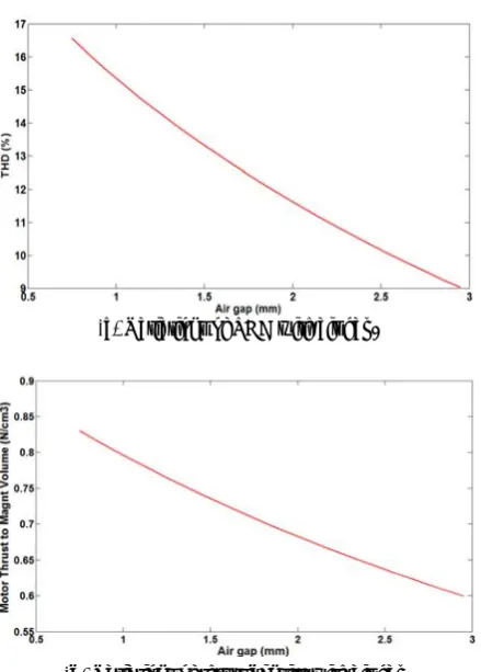
Figures 3-c and 3-d show the variations of objective functions with the air gap length when the magnet width and height are constant. Both THD and thrust density reduce with an increase in air gap length.
Table 2 Design Constrains [1].
Parameter Sym bol
Mi n
M ax Air gap length [mm] g 0.7
5
3 Magnet Width [mm] wPM 12 24
Magnet height [mm] hPM 1 3
Thrust force [N] Fav 29.
44
-
3.2 Optimization Method
Particle Swarm Optimization is an evolutionary computation algorithm developed by Kennedy and Eberhart in 1995 [14]. PSO mimics the social behavior of a flock of birds where information is shared among the individuals of the population. It starts with an initial swarm of random particles in the search space where each particle is also assigned a randomized velocity. The velocity of each particle is dynamically updated based on the particle’s best previous position reached and the best position reached among previous generations [14].
The position and the velocity of a particle in a PSO algorithm is updated at each iteration towards its Pi and Pg positions according to (9) and (10):
(a) Variations of THD with magnet dimensions.
(b) Variations of thrust density with magnet dimensions.
(c) Variations of THD with air gap.
(d) Variations of thrust density with air gap.
Fig. 3 Variation of objective functions versus design variables.
) x p ().( rand . c
) x p ().( rand . c v . w v
id gd 2
id id 1
id id
− +
− +
=
(9)
id id id x v
x = + (10)
where w is inertia weight, c1 and c2 are acceleration constants, and rand() is a random function in the range [0, 1]. The first term in (9) represents the inertia of previous velocity, the second is the “cognition” part which represents the private thinking of a particle, and the third term is the “social” part which represents the sharing of information among the population. The velocity of each particle is limited by Vmax when the updated velocity exceeds this value. Vmax is determined by the user and represents the resolution of the search process between the present position and the target position [14]. The flowchart of this algorithm is shown in Fig. 4. More details about this algorithm are presented in [14].
In this paper the objective function of the optimization problem is (8). Optimization variables are the height of magnet (hm), Magnet width (WM) and air
gap length (g) with constrains mentioned in Table 2.
4 Results
The method described in section 3-2 is used to optimize the design of a typical linear Brushless permanent magnet motor with specifications as presented in Table 1. Optimization is done in three cases, resulting different designs. These cases are explained in section 3-1.
Design variables in these cases are listed in Table 3. Table 4 and Fig. 5 show the characteristics of motor in the different optimization problems and those of typical motor.
It can be seen in Table 4 and Fig. 5 that the typical motor has the efficiency of 90.59%, thrust and THD of 29.44 N and 4.89% respectively. The ratio of thrust to PM volume in this motor is 0.57 N/Cm3.
Optimal design 1 carried out just considering the THD of Bys as objective function. In this optimization THD is reduced almost 58.40% with respect to the typical motor. The thrust density, thrust force and efficiency are modified almost 29.82%, 9.95% and 0.61% respectively.
In optimal design 2 we just optimized thrust density. Results shows motor thrust density has improved more than 440% and increased to 2.51 N/cm3. At the same time efficiency and thrust are constant. In contrast, The THD deteriorated almost 364% (has increased to 17.82 in this case).
In optimal design 3 thrust density and thrust ripple are simultaneously considered in the objective function by deciding nonzero values for m and n in (8).
In this case, the results of the design optimization show that motor thrust has improved 9.85%. This multi-objective optimization provides a design with almost 70.38% less thrust ripple (THD) and 29.82% more thrust density with respect to the typical motor, while the efficiency is increased almost 0.61% too. This proves that proposed optimization method is effectiveness in optimizing all of the objective functions simultaneously.
Fig. 4 Flowchart of the particle swarm optimization (PSO) [14].
Table 3 Dimensions of optimized motor for different objective functions.
Parameter
Typic al motor
Optimal Design 1
Optimal Design 2
Optimal Design 3 m=1, n =0 n=1, m=0 m=n =1 Air gap
length (mm) 3 2.20 0.75 2.18 Magnet
Width (mm) 17.5 19.70 12 19.61 Magnet
height (mm) 3 2.28 1 2.27
Table 4 The characteristics of optimized motor.
Parameter Typical motor
Optimal Design 1
Optimal Design 2
Optimal Design 3 m=1, n
=0
n=1,
m=0 m=n =1 THD (%) 4.89 2.856 17.82 2.87
Thrust/PM Vol.
(N/Cm3) 0.57 0.74 2.51 0.74
Thrust Force (N) 29.44 32.37 29.44 32.34 Efficiency (%) 90.59 91.14 90.59 91.14
5 Design Evaluation
To verify the results of optimization, it is important to use a finite element simulation. The optimization is carried out based on the analytical model of the motor. This model is presented in section 2 and evaluated by using some simplifications such as limited motor length. So, 2-D nonlinear FEM is employed to validate the model.
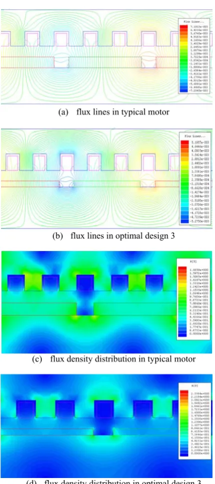
A flowchart of the FEM is shown in Fig. 6. Fig. 7 shows a graphical representation of the flux lines and flux density distribution in the typical motor and optimal design 3. Fig. 8 and 9 show the flux density distribution in motor length for the mentioned designs. It can be resulted from Fig. 10 that the flux density of optimal design 3 is more near to sinusoidal one and it leads to less THD for optimal design 3.
Ty
p
ic
a
l Op
ti
ma
l 1
Op
ti
m
a
l 2 Op
ti
m
a
l 3
90 90.5 91 91.5 92
E
ff
icien
cy
(
%
)
(a)
Ty
pi
ca
l Op
ti
ma
l 1
Op
ti
ma
l 2
Op
ti
ma
l 3
27 28 29 30 31 32 33
Th
r
u
st
(N
)
(b)
Ty
pi
ca
l
Op
ti
ma
l 1
Op
ti
ma
l 2
Opt
imal
3
0 2 4 6 8 10 12 14 16 18
TH
D
(
%
)
(c)
Typi
ca
l
Op
ti
ma
l 1
Op
ti
ma
l 2
Op
ti
ma
l 3
0 0.5 1 1.5 2 2.5 3
Th
ru
st
D
ens
it
y
N/
Cm
^
3
)
(d)
Fig. 5 The characteristics of the typical and optimized motors.
Fig. 6 Flowchart of FEA [3].
(a) flux lines in typical motor
(b) flux lines in optimal design 3
(c) flux density distribution in typical motor
(d) flux density distribution in optimal design 3
Fig. 7 Flux lines and flux density distribution in the linear
BLPM motors.
Fig. 8 Flux density distribution in typical motor.
Fig. 9 Flux density distribution in optimized motor.
Fig. 10 Flux density harmonics.
6 Conclusions
The advantages of the linear brushless permanent magnet motors cause their increasingly uses in various applications. But, thrust ripple and thrust density are the main disadvantages of these motors which need optimization. In this paper a multi-objective optimization method based on particle swarm optimization (PSO) is used. At first, the optimal dimensions of the permanent magnet and air gap length are calculated by PSO to minimize the thrust ripple. Then, another objective function (thrust density) is considered to be maximumized. The mentioned search algorithm calculates the best answers for improving the ratio of the thrust to the permanent magnet volume. Finally, a multi-objective optimization is carried out and the best dimensions are searched to minimize thrust ripple and maximize the thrust density, simultaneously. The results of the analysis show that motor thrust has improved 9.85%. It means, this multi-objective optimization process provides a design with almost 40.83% less thrust ripple (THD) and 85.42% more thrust density with respect to the typical motor while the efficiency is increased almost 0.59% too. This proves the effectiveness of the used optimization method in simultaneously optimizing all the objective functions. Finally, finite element simulation verified the results.
References
[1] Chung M. J. and Gweon D. G., "Design Optimization and Development of Linear Brushless Permanent Magnet Motor",
International Journal of Control, Automation, and Systems, Vol. 1, No. 3, pp. 351-357,
September 2003.
[2] Chung M. J., Lee M. G., Lee S. Q., Kim S. M. and Gweon D. G., "A Method of Optimal Design for Minimization of Force Ripple in Linear Brushless Permanent Magnet Motor", IEEE Industry Applications Conference, 2000.
[3] Kang G. H., Hong J. P. and Kim G. T., “A novel design of an air-core type permanent magnet linear brushless motor by space harmonics field analysis,” IEEE Trans. Magn., Vol. 37, No. 5, pp.
3732–3736, Sep. 2001.
[4] Takedomi S. and Hanyo U., "Linear motor", U.S. Patent 5 087 844A, Feb. 11, 1992.
[5] Miyashita T. and Onodera S., “Permanent magnet rotary motor,” U.S. Patent 2005/0258698A1,
Nov. 24, 2005.
[6] Domeki H. and Yamanaka Y., “Permanent magnet motor,” U.S. Patent 2005/0264122 A1,
Dec. 1, 2005.
[7] Li Y., Zhou J., and Lu Y., “Optimum design of magnet shape in permanent magnet synchronous motors,” IEEE Trans. Magn., Vol. 39, No. 6, pp.
3523–3526, Nov. 2003.
[8] Borghi C. A., Casadei D., Fabbri M. and Serra G., “Reduction of the torque ripple in permanent magnet actuators by a multi-objective minimization technique,” IEEE Trans. Magn.,
Vol. 34, No. 5, pp. 2869–2872, Sep. 1998. [9] Borghi C. A., Casadei D., Cristofolini A., Fabbri
M. and Serra G., “Application of a multi-objective minimization technique for reducing the torque ripple in permanent magnet motors,” IEEE Trans. Magn., Vol. 35, No. 5, pp. 4238–4246,
Sep. 1999.
[10] Kim M. Y., Kim Y. C. and Kim G. T., “Design of slotless-type PMLSM for high power density using divided PM,” IEEE Trans. Magn., Vol. 40,
No. 2, pp. 746–749, Mar. 2004.
[11] Matsunobu Y., “Permanent magnet rotating electric machine,” U.S. Patent 6 815 858 B2,
Nov. 9, 2004.
[12] Chung M. J., Lee M. G., Lee S. Q. and Gweon D., "Optimal Design and Development of Linear Brushless Permanent Magnet Motor", IEEE conference, pp. 436-441, 2001.
[13] Isfahani H., Vaez-zadeh S. and Rahman M. A., "UsingModular Pole for Shape Optimization of Flux Density Distribution in Permanent-Magnet Machines", IEEE Trans. On Magnetics, Vol. 44,
No. 8, pp. 1009-2015, Aug. 2008.
[14] Arkadan A.A., ElBsat M. N. and Mneimneh M. A., "Particle Swarm Design Optimization of ALA Rotor SynRM for Traction Applications", IEEE
Trans. On Magnetics, Vol. 45, No. 3, pp.
956-959, March 2009.
Caro Lucas received the M.S. degree from the University of Tehran, Tehran, Iran in 1973 and the Ph.D. degree from the University of California, Berkeley, in 1976. He is a Professor, and a member (as well as the founder-Director) of Center of Excellence for Control and Intelligent Processing, Department of Electrical and Computer Engineering, University of Tehran, as well as a Researcher at the School of Cognitive Sciences (SCS), Institute for Studies in Theoretical Physics and Mathematics (IPM), Tehran, Iran. He has served as the Director of Intelligent Systems Research Faculty, IPM (1993-1997) and Chairman of the ECE Department at the University of Tehran (1986-1988). He was also a Visiting Associate Professor at the University of Toronto, Toronto, Canada (summer, 1989-1990), University of California, Berkeley (1988-1989), an Assistant Professor at Garyounis University (1984-1985), University of California, Los Angeles (1975-1976), a Senior Researcher at the International Center for Theoretical Physics, and the International Center for Genetic Engineering and Biotechnology, both in Trieste, Italy, the Institute of Applied Mathematics, Chinese Academy of Sciences, Harbin Institute of Electrical Technology, a Research Associate at the Manufacturing Research Corporation of Ontario, and a Research Assistant at the Electronic Research Laboratory, University of California, Berkeley. His research interests include biological computing, computational intelligence, uncertain systems, intelligent control, neural networks, multiagent systems, data mining, business intelligence, financial modeling, and knowledge management. He was the founder of the ISRF, IPM and has assisted in founding several new research organizations and engineering disciplines in Iran. He is the holder of the patent for Speaker Independent Farsi Isolated Word Neurorecognizer. Dr. Lucas has served as Managing Editor of the Memories of the Engineering Faculty, University of Tehran (1979-1991), Reviewer of
Mathematical Reviewers (since 1987), Associate Editor of the Journal of Intelligent and Fuzzy Systems (1992-1999), and Chairman of the IEEE, Iran Section (1990-1992). He has served as the Chairman of several international conferences.
Farid Tootoonchian has received his B.Sc. and M.Sc. degrees in Electrical Engineering from the Iran University of Sciences and Technology, Tehran, Iran in 2000 & 2007 respectively. He has done over 22 industrial projects including one national project, held 5 patents, published more than 8 journal and 22 conference papers about electrical machines and sensors over the years. His research interest is design of small electromagnetic measurement machines and sensors.
Zahra Nasiri-Gheidari has received her B.Sc. degree in Electrical Engineering from the Iran University of Science and Technology, Tehran, Iran in 2004. And she received the Master degree in Electrical Power Engineering from the University of Tehran in 2006, graduating with First Class Honors in both of them. She is currently director of the Electrical machines Lab. in the Electrical Engineering Department of Sharif University of Technology, Tehran, Iran. Her research interests are design and modeling of electrical machines and drives.
![Fig. 2 Simplified analytical model [2]](https://thumb-us.123doks.com/thumbv2/123dok_us/216228.2016080/2.595.311.546.411.705/fig-simplified-analytical-model.webp)
![Table 2 Design Constrains [1]. Parameter](https://thumb-us.123doks.com/thumbv2/123dok_us/216228.2016080/3.595.313.540.477.559/table-design-constrains-parameter.webp)
![Fig. 4 Flowchart of the particle swarm optimization (PSO) [14].](https://thumb-us.123doks.com/thumbv2/123dok_us/216228.2016080/5.595.61.280.59.271/fig-flowchart-particle-swarm-optimization-pso.webp)