On the Self Similar Energy Gain Scaling in
Isobaric Approach of ICF Targets
S. Koshbinfar and A. Ghasemizad
*Department of Physics, Faculty of Science, Guilan University, Rasht, Islamic Republic of Iran
Abstract
In this paper we start with Meyer-Ter-Vehn isobaric fusion model and try to
reconstruct all equations by introducing a dimensionless variable
ψ
i=r
i/R
m. Then
we investigate the proper sets of spark confinement parameter and temperature
{H
s,T
s} which satisfy ignition conditions of spark ignition in deuterium-tritium
(DT) equimolar mixture in terms of isentrope parameter,
α
, implosion velocity,
U
im. Finally, limiting fuel energy gain curve (
G
f*
) as function of ignition energy
(
E
ign) for different implosion velocities is calculated. By this simple modification
of our original formulation, we obtain fuel energy scaling as E
f∝
α
3U
im−10for
desirable range of ignition parameters. Since in our formulation H
sT
sproduct has
appeared, it enabled us to insert a scaling relation for ignition condition in fuel
energy, E
fwhich this in turn decreases implosion velocity exponent in our scaling
relation to 7.0.
Keywords: Isobaric model; Central spark ignition; Self-similar; Energy gain; Energy gain scaling
*
E-mail: ghasemi@guilan.ac.ir
I. Introduction
The Vast efforts have taken place to achieve the generation of energy from controlled nuclear fusion both in magnetic confinement fusion (MCF) and inertial confinement fusion (ICF) [1]. ICF is an approach to fusion that relies on the inertia of the fuel mass to provide confinement. It is based on micro explosion of thermonuclear targets:
17.6
D T+ → + +α n MeV (1)
A major challenge has always been to come up with target design that would be appropriate for energy production[2] i.e. major scientific requirement for using ICF is to reach high energy gain Gf:
TN f
f E G
E
= (2)
II. Admissible Criterion for Thermonuclear Burn of a Bare DT Microsphere
In inertial confinement fusion, a spherical shell of cryogenic deuterium and tritium (DT) filled with DT gas is accelerated by direct laser irradiation (direct drive) or x rays produced by a high-Z enclosure (indirect drive). When an intense laser beam is uniformly impinged on a spherical fuel pellet with intensity of the order of 1014-1015 Wcm−2, the laser energy is absorbed on the surface to generate high temperature plasma of 2-3 keV, and eventually an extremely high pressure of a few hundred mega-bars is generated. The mechanism of the acceleration is the same as rocket propulsion [3]. When the accelerated fuel collides at the center, compression and heating occur. If the dynamics are sufficiently spherically symmetric, the central area is heated up to 5-10 keV (is called the ‘central spark’), and a fusion reaction starts. In fusion reactor scale implosions, a fuel pellet with an initial radius of about 3 mm should be compressed to a radius of about 100 µm. For this purpose, highly precise uniformity is required for irradiation intensity distribution over the fuel pellet as well as high quality sphericity and uniformity of the fuel pellet. The implosion velocity for achieving the fusion ignition temperature of 5-10 keV at the centre of fuel is required to be (3-4)× 107 cm s−1. Therefore, the pulse length of the laser should be 10-20 ns, and in this time-scale the directed mega-joule energy has to be delivered to a fuel pellet of radius about 3 mm [4].
According to isobaric model of fusion targets in inertial confinement fusion, it is assumed that at the final stage of hydrodynamic implosion, target configuration is composed of two distinct regions called as spark and cold fuel region [5]. The spark region is an ideal plasma of hydrogen isotopes with density, temperature and radius of ρs, Ts and Rs, respectively. On the other hand, the cold fuel region is a degenerate electron gas of parameters ρc, Tc and Rm, respectively. It is also assumed that pressure is constant across the whole target at stagnation time (maximum compression). A spark with given values of temperature, Ts, and its confinement parameters,
Hs=ρsRs, can be produced by hydrodynamic implosion process which then ignites and propagates burning waves in the cold region. There exist processes here which cool and dissipate spark region. Most important of them are bremsstrahlung energy losses of hydrogen isotope plasma and electron thermal conductivity [6].
As a capsule implodes Alpha-particle deposition from thermonuclear burn of DT try to heat the central hot spot region. On the other hand, electron conduction
from the hot spot to cold surrounding fuel as well as radiative losses acts to cool the hot spot. If conduction and radiative losses from the hot spot is too large, the ignition process never occurs. To achieve ignition by the time the implosion process has stopped, hot spot must have a ρr equal to about 0.3-0.4 g/cm2 and must achieve a central temperature of about 5-10 KeV. Under this condition, α-particle energy deposition can overcome loss processes and a self sustaining burn wave will be generated. At first, we consider that the dominant radiation loss in fuel target, Pbr is bremsstrahlung emission which escapes from the fuel and its power density is given by:
37 1/ 2 3
5.36 10 ( ) /
br e D T e
P = × − n n +n T W m (3)
where Te is electron temperature and ne, nD and nT are electron, deuterium and tritium densities, respectively. Assuming equal number densities (ne=ni=ns) and temperatures (Te=Ti=Ts) of electron and ions in hydrogen plasma we have:
37 2 1/ 2 3
5.36 10 /
br s s
P = × − n T W m (4)
On the other hand, the conduction loss power density, Pec, is obtained by assuming power law dependence for heat conduction coefficient and by applying Spitzer conductivity for deuterium-tritium plasma:
3 2
1.74 s /
ec ec
s
KT
P W m
R κ
= (5)
here, K=1.6×10⁻¹⁶ J/KeV is Boltzmann's constant and
ec
κ is electron heat conduction coefficient.
Now, we introduce a self-similar parameter, ψ, which is defined as ratio of a specific layer to fuel radius at stagnation time. By this definition we would be able to consider the evolution of class of pellet designs with definite values of spark/fuel ratio [7]:
i i
m
r R
ψ = (6)
1/ 2
3 2 3
3 2 5
10 2 3 5 (3 )
(1 )
m
s s
s s im
im s s
R
H T Y
JT U
J U ψ ψ ψ
−
=
⎡⎛ ⎞ ⎤
−
⎢⎜ ⎟ ⎥
− ⎝ ⎠
⎢ ⎥
⎣ ⎦
(7)
where J = 77.2 MJ/g.KeV and Y = 2.18×10⁻³ Pa.m5.Kg−5/3are constants.
It is obvious that necessary condition for ignition is that the amounts of energy in gain processes overcome loss processes. In our case, this means that the thermonuclear energy release exceeds cooling energy losses process across spark region. Thermonuclear heating rate per unit volume, power density, is obtained from burn rate and the fractional alpha particle deposition and is given by:
3
/
TN DT D T
P = 〈σv〉 n n f Qα α W m (8)
where <σv>DT is Maxwellian averaged fusion rate of a DT mixture, fα is α-particles deposition factor i.e.
fractions of alpha particles that remain in spark region and deposit their energies there and Qα is alpha particles
birth energy at spark center which is equal 3.5 MeV. The DT fuel in the hot spot region undergoes a thermonuclear spark whenever the net energy release during the confinement period becomes comparable to the initial energy content of DT plasma. In a good approximation, an effective confinement time scale which allows ignition of cold fuel surrounded hot region is given by:
m c
im
R t
U
∆ ≅ (9)
So ignition condition in this frame can be written as:
3
( )
2
TN ec br c i s
i
P −P −P ∆ ≅t
∑
n KT (10)where sum is over ion and electron densities. With sub-stituting for corresponding expressions its final form is:
18
5 / 2 3
7.11 10
26.96 2.97 10
s DT
s
s s
s s
im s
H f v
T
H T
H T
U
α σ
ψ
−
〈 〉 ×
− − ×
≅
(11)
As could be seen, the right hand side of this equation is only a function of products of implosion velocity and spark fractional radius. To obtain a good Physical picture of spark parameter in HT plane we apply a numerical solution of this expression for three right
hand values of 0, 4 and 8 which gives ignition boundary curves for admissible values of spark parameters which satisfy our ignition condition and is shown in Figure 1. In the limit of prolonged confinement period, Uimψs<<107 cm/s, ignition condition is defined by equilibrium of heating and cooling processes, Pα=Pbr+Pec, then it is independent of implosion velocity and spark fractional radius. In contrast, for short confinement period, Uimψs>>107 cm/s, ignition boundary shows a sensitive behavior to implosion velocity and spark fractional radius changes. For its larger value ignition boundary curve lies further with respect to prolonged confinement situation and HsTs product has a minimum value.
We perform a series of numerical calculations in order to find HsTs product dependence on implosion velocity and spark fractional radius for spark temperature7≤Ts (KeV )≤12, fractional spark radius
0.2≤ψs ≤0.9 and implosion velocity 2 10× 7 ≤ 7
( / ) 6 10
im
U cm s ≤ × . We obtain a linear propor-tionality for ignition criterion:
s s im s
H T ∝U ψ (12)
The latter relation not only gives ignition threshold for the product HsTs but also its minimum value along the ignition boundary which lies between 7 to 12 KeV. It should also be noticed that left branch of these curves which approximately coincide on each other will also give us an important result of self-ignition temperature of about 4.4 KeV for deuterium-tritium plasma at ignition configuration. Higher values of RHS of Eq. (11) correspond to short confinement time and high implosion velocity and its lower values for a prolonged confinement of fusion plasma and small implosion velocity. However if the fuel pellet is optically thick for an opacity length of la, it has several thickness units from the center to the edge and most of radiated energy is trapped inside it and radiation loss is reduced.
III. Energy Gain
, 0 ( )
, 1
s s
c s
ρ ψ ψ
ρ ψ
ρ ψ ψ
≤ ≤ ⎧⎪
= ⎨
< ≤
⎪⎩ (13)
where ρs <ρcand subscripts denote hot spark and cold
main fuel regions, respectively and the pressure, P, is constant in entire fuel volume. Assuming ideal gas equation of state for spark region, we have:
s s s
P =Jρ T (14)
On the other hand, adopting a constant value of isentrope parameter throughout cold fuel region:
deg
c
P P
α= =
( pressure of main fuel)
( Fermi pressure at the density of cold main fuel) (15)
So, our final expression for pressure balance in compressed fuel is obtained:
5 / 3
s s s c
P =Jρ T =Yαρ (16)
Using Eq. (16), we can easily evaluate spark and fuel region densities dependence. So, we have constructed our ignition configuration with five independent parameters Hs (g/cm2), ψs, α, Ts (KeV), and Uim (in units of 107 cm/sec). Using equation of mass:
2 2 3
4
[ (1 )]
3
f m s s c m s
M = πR H ψ +ρ R −ψ (17)
the following expression for spark and cold region energies can be obtained:
2 2 4 s
s s s m
DT
K
E H T R
m πψ
= (18)
3
16 2 (1 )
5.18 10 s
c s s m
s
E H T R ψ
ψ
−
= × (19)
Now, we can use energy balance equation to obtain an explicit expression for compressed fuel radius in terms of ignition parameters:
2
3 1
2 2
f s f im
E = P V = M U (20)
By substitution of Eq. (7) in Eq. (20) we will obtain a relation for fuel energy, Ef as function of ψs, α, Uim, Ts and Hs:
( )
3 13 2 10 f E JY π − = ×(
)
(
)
5 33 3 2
5 10 3 3
3 1
s s s im
s
im s s
H T U
JT U α ψ ψ ψ ⎛ ⎞ × ⎜⎜ − ⎟⎟ ⎝ ⎠
− (21)
Above equation shows a weak dependence on implosion velocity and it does not give us exact power law dependence for energy scaling. Since we look for a fuel energy scaling relation of the form Ef %α3.0UimB where B is constant, we perform a series of numerical calculation to obtain a power law dependence on implosion velocity for fuel energy by assuming
5 im
U ≤ , 5≤Ts (KeV )≤12, 0.4≤Hs (g cm/ 2)≤1.0
and 0.2≤ψs ≤0.9 for our isobaric configuration
(
)
3.0 2.35 3.0 10.0f s s s im
E ∝ψ − α H T U − (22)
By this modification, our results reproduced in a good manner the energy scaling relation of the Basko self-similar fusion model [8] and Meyer-Ter-Vehn model [9].
Thermonuclear energy gain with respect to energy invested in the fuel is calculated as:
TN f
f DT b
DT f
E M
G f
E ε E
= = (23)
where εDT is the specific DT energy, 3.34×10¹¹ MJ/g and fb is fuel burn fraction:
(1 )
7.0 (1 )
s c m s
F b
F s c m s B
H R
H f
H H R H
ρ ψ
ρ ψ
+ −
= =
+ + − + (24)
where HF is fuel areal density.
The optimum value of fractional spark radius for 5
im
U ≤ is ψs,opm≅0.56-0.58. It tells us about the most economical regime of ignition where maximum fuel mass can be ignited by a given ignition energy [8]. In our reconstruction of the original isobaric model formula in terms of self similar variable, ψ, a product of HsTs in Eq. (21) has appeared which this matter help us to invoke to our previous result in Sec. II at ignition time and insert it in our fuel energy relation, which it cause to suppress our previous energy scaling exponent of implosion velocity to 7.0:
(
)
3.0 0.14 3.0 7.0f s s s im
E ∝ψ α H T U − (25)
The results of our numerical calculation is obtained for Uim ≤5 cm/s, 5≤Ts (KeV )≤12 and 0.2≤
0.9
s
Figure 1. Ignition boundary for three set of RHS values 0, 4 and 8.
Figure 2. Fuel gain curves (full lines) and limiting fuel gain curve (dash line) as function of compressed fuel energy.
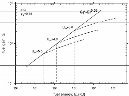
Figure 3. Fuel gain curves (dash lines) and limiting fuel gain curve (full line) as function of compressed fuel energy for case that we insert HsTs in our relations.
IV. Limiting Energy Gain
The question about required amount of energy for a proper ignition of fusion capsule is one of the aims in ICF research and has a lot of importance in optimization of target design and drivers (lasers or accelerators) , since we want to reach to the highest value of energy gain with a given driver energy, Gf (Edr). A gain curve that is obtained for a given value of implosion velocity represents a class of capsule design with different sizes. Any such curve has an ignition threshold, Edr,min, since for a given implosion velocity, Uim, arbitrary fuel masses for ignition is not allowed. The envelope of gain curves for different implosion velocity is the limiting (fuel) gain curve, (Gf*) GT*. If we plot fuel gain as function of ignition energy for fixed implosion velocity and limited values of spark fractional radius 0.1<ψs<0.9, we will obtain a series of gain curves. The envelope of these gain curves has been shown with a dash line Gf* and is proportional to Ef0.32 which was calculated numerically and is shown in Figure 2 [10]. This result is in good agreement with one that obtained by Basko by self-similar solution of hydrodynamics equations for a bare DT sphere in its simple approximation without any additional constraints like hydrodynamics instability and drive asymmetry. When we take into account direct dependence of our relation to HsTs and insert it in scaling relation, we could obtain a more relaxed scaling expression for limiting energy gain line by applying a series of numerical calculation for 0.1<ψs<0.9 which is shown in Figure 3 [11]. In this diagram we fixed spark radius near to its optimum condition. These results lead to limiting fuel gain Ef0.36 which is the same as Basko scaling [8].
V. Conclusion
In this paper, it is shown that for ICF targets considered with plasma cooling processes, a limited sets of {Hs, Ts} values are obtained that satisfy ignition conditions. Ignition boundary curve gives us universal admissible values of spark parameters. Then we perform a series of numerical calculation to obtain HsTs dependence on stagnation configuration. It yields direct proportionality dependence to implosion velocity and spark fractional radius.
energy scaling Basko [8] and Meyer-Ter-Vehn [9]. Then due to the appearance of HsTs product in our fuel energy relation we are able to find a better scaling relation by inserting HsTs were derived in Sec.II in our relations which it in turn suppresses implosion velocity exponent in energy scaling. In this way, we obtain final expression for energy scaling Ef%α3.0Uim−7.0.
After that, a series of fuel energy gain curves as function of fuel energy for different implosion velocity were plotted and the envelope of the gain curves was calculated numerically without applying HsTs scaling.
The relation 0.32
*f f
G ∝E was obtained which is in good accordance with the relation obtained by Basko [8]. In continue we look for a limiting gain curve slope by inserting HsTs scaling obtained in Sec. II. This causes to suppress implosion velocity exponent in energy sca-ling to 7.0. The nature of both calculations are the same but a small difference in details appears due to some more realistic assumptions about pressure, density and temperature profile of compressed fuel at ignition time.
References
1. Yamanaka C. Inertial fusion research over past 30 years. Fusion Engineering and Design, 44: 1-12 (1999).
2. Basko M.M., New developments in the theory of ICF targets and fast ignition with heavy ions. Plasma Phys. Control. Fusion, 45: A125-132 (2003).
3. Nakai S. and Mima K. Laser driven inertial fusion energy: Present and prospective. Rep. Prog. Phys., 67: 321-349 (2004).
4. Nakai S. and Takabe H. Principles of inertial confinement fusion- physics of implosion and the concept of inertial fusion energy. Rep. Prog. Phys., 59: 1071-1131 (1996). 5. Meyer-Ter-vehn J. On energy gain of fusion targets: The
model of kidder and bodner improved, Nucl. Fusion, 22: 561-565 (1982).
6. Ghasemizad A. and Khoshbinfar S. Proc. Int. Conference on Nuclear Option in countries with Small and Medium Electricity Grids, Dubrovnik, Croatia, May 16-20 (2004). 7. Choudhauri The Physics of Fluids and Plasmas.
Cambridge University Press, pp. 104-128 (1999).
8. Basko M.M. On the scaling of the energy gain of ICF targets. Nucl. Fusion, 35: 87-99 (1995).
9. Murakkami M. and Meyer-Ter-Vehn J. Indirectly driven targets for inertial confinement fusion. Ibid., 31: 1315-1331 (1991).
10. Ghasemizad A. and Khoshbinfar S. On the Investigation of spark formation conditions and energy gain in inertial confinement fusion. Iranian Journal of Science and Technology, Transaction A, 29(A3): 421-431.