International Journal of Engineering
J o u r n a l H o m e p a g e : w w w . i j e . i rReliability and Performance Evaluation of Fault-aware Routing Methods for
Network-on-Chip Architectures
M. Valinataj*
School of Electrical and Computer Engineering, Babol University of Technology, Babol, Iran
P A P E R I N F O
Paper history:
Received 21 November 2012 Received in revised form 30 July 2013 Accepted 07 November 2013
Keywords: Network-on-Chip Routing Algorithm Reliability Performance Fault
Analytical Model
A B S T R A C T
Nowadays, faults and failures are increasing especially in complex systems such as Network-on-Chip (NoC) based Systems-on-a-Chip (SoC) due to the increasing susceptibility and decreasing feature sizes. On the other hand, fault-tolerant routing algorithms have an evident effect on tolerating permanent faults and improving the reliability of a NoC based system. This paper presents reliability and performance evaluation of two main kinds of fault-aware routing algorithms, deterministic and adaptive, used in NoC architectures. The investigated methods have a multi-level structure for fault-tolerance and therefore, each level can be separately evaluated. To demonstrate the effectiveness of these methods, we propose an analytical approach for reliability assessment based on combinatorial reliability models to show the effect of fault-aware routing algorithms on overall NoC reliability. However, for performance evaluation, we conduct extensive simulations on different applications.
doi:10.5829/idosi.ije.2014.27.04a.01
1. INTRODUCTION1
The advent of complex systems such as Network-on-Chip (NoC) based on Multi-Processor Systems-on-a-Chip (MPSoC); with an increase in vulnerability of integrated circuits to environmental are essentional for manufacturing and operational phases design, analysis and evaluation of fault-tolerant complex systems.
An approach to achieve reliable NoCs is incorporated network level fault-tolerance by designing fault-tolerant routing algorithms. For this purpose, many fault-tolerant routing algorithms have been designed for NoCs. However, in this paper the basic methods, are mainly considerd the methods introduced in literature [1, 2]; which are designed for two-dimensional (2D) mesh NoCs. The introduced method in the article [1] is a deterministic routing but the method proposed in another article [2] is an adaptive routing algorithm. However, both are distributed, reconfigurable and fault-aware through the use of a small configuration register in each router to store the local fault information. In these methods, a modified built-in-self-test (BIST) mechanism such as the ones used in other works [3, 4]
*Corresponding Author Email:[email protected] (M. Valinataj)
detects the faulty links, and then, stores the fault information in the appropriate configuration registers.
It is worth mentioning that the reliability assessment is a key method for dependability evaluation which can be used to make decisions in the design of reliable systems [5]. The reliability assessment can be done in two ways, analytically or by simulation. Reliability evaluations in the literature [1, 2] are performed by simulation. Thus, in this paper we use the analytical reliability evaluation for those methods. Sajjadi-Kia and Ababei [6] proposed a new circuit level reliability evaluation methodology and applied it to a NoC router to identify the more vulnerable sub-blocks. Shafik and and Al-Hashimi [7] introduced an application-specific simulation-based reliability analysis for NoC architectures. However, a simulation framework for system reliability evaluation is discussed in the literature [8] to be used for NoC-based MPSoC designs. Bhardwaj et al. [9] proposed an analytical reliability assessment for the large computer or communication networks using neuro optimization. However, there is not much work on analytical reliability evaluation for NoCs despite simulation-based reliability evaluation and performance evaluation. The main works are presented in the literature [5, 10, 11]. In the work of
Valinataj et al. [5] analytical reliability assessment of mesh and torus-based NoCs are performed with respect to different routing algorithms, traffic models and network sizes. Lehtonen et al. [10] presented a fault-tolerant analysis of different mesh NoC architectures including the topology, the router structure and the number of network interfaces. A different analytical model is presented by Refan et al. [11] that estimates the effect of its proposed fault-tolerant NoC architecture on the reliability. However, this analytical model is application-specific. But in this paper, we propose an application-independent approach.
The rest of the paper is organized as follows. In Section 2 a background is described to introduce the fault-tolerant routing algorithms proposed in the literature [1, 2]. In Section 3 the proposed analytical reliability evaluation approach is explained and then, it is applied to the mentioned methods. Section 4 describes simulation-based performance evaluation, and finally, conclusions are drawn in Section 5.
2. BACKGROUND
2. 1. Preliminaries The methods introduced in the literature [1, 2] have common basic concepts. In addition, both have a multi-level or hierarchical structure, which means they are capable to tolerate more faulty components in higher levels. The work presented by Valinataj et al. [1] includes the FT_XY (Fault-Tolerant XY) and the FT_XY3 routing algorithms, and another work [2] includes the Basic-RAFT (Reconfigurable, Adaptive and Fault-Tolerant) and the Main-RAFT (including RAFT1 and RAFT2) routing algorithms (A modified version of the work of Valinataj et al. [1] is proposed in the other work [12]). The FT_XY and the Basic-RAFT routing algorithms tolerate all one-faulty-link situations and single faulty links with the main difference that the first is deterministic but the second is adaptive. In the other words, FT_XY is the Fault-Tolerant version of XY routing algorithm but the Basic-RAFT is the Fault-Tolerant version of DyXY routing method introduced in the literature [13]. There are other differences between these two types of methods. To avoid deadlock condition, the method proposed by Valinataj et al. [1] uses turn model but the method introduced in another work [2] uses virtual channels (VC). Furthermore, the method in the work [2] utilizes congestion information in addition to fault information to route the packets. The next levels of both methods tolerate multiple faulty links, but RAFT2 also tolerates faulty routers. These methods have common characteristics, too. Both are scalable because they are distributed routing algorithms and do not use routing tables. It is an advantageous property since routing table based algorithms are not properly scaled with the
increasing NoC size in terms of latency, area and power dissipation, thus being impractical for NoCs [14, 15]. In the following, we describe the common concepts used in both methods. Before that, it should be noted that we assume the links are bidirectional and when any type of permanent faults occurs in any direction of a link, the entire link will be considered as faulty.
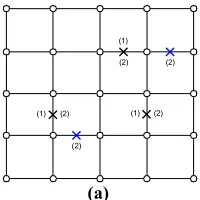
Definition 1: In a 2D mesh each link has two direct neighbouring nodes west and east (W,E) or north and south (N,S) and at most four indirect neighbouring nodes (NW,NE,SW,SE) or (WN,EN,WS,ES) based on its horizontal or vertical orientation (Figure 1).
Definition 2: Each link has a contour including all
direct and indirect neighbouring nodes and their interconnecting links.
Definition 3: Each node has at most four direct
neighbouring links in its north, south, east or west directions.
There are 6 different contours for links (faulty or healthy) corresponding to six types of positions. Two contours C1 and C2 shown in Figure 1 are for the non-border links but other contours are for the links located on one of mesh borders. In Figure 1, "×" represents a broken or faulty link. We can achieve a faulty-link tolerant routing algorithm if we route the packets through a cycle-free contour surrounding a faulty link. In turn-based method ([1]) the cycles of contours C1 and C2 are broken by prohibiting two turns in NE router for C1 and two turns in EN router for C2. But the method introduced by Valinataj et al. [2] uses an additional virtual channel to become deadlock free.
2.2. Path Selection Procedure by Reconiguration To achieve fault-tolerance, the method introduced by Valinataj et al. [1] uses the reconfiguration by defining new unique and deterministic paths instead of the broken paths for all routers on a cycle-free contour around a faulty link. Other routers use the paths based on the XY routing algorithm. The old paths (P1 to P12) and new paths (NP1 to NP12) are shown in Figure 1a. The method introduced in the literature [2] operates in such a way that if there are two possible directions to move towards a destination, it selects the direction with smaller traffic load. In addition, similar to the work proposed by Valinataj et al. [1] it defines a new routing algorithm for all routers inside a contour surrounding a faulty link. This process does not comprise any message passing between adjacent routers. Other routers use the paths selected by the adaptive routing algorithm (DyXY) when no faulty link exists in the network. In Figure 1b, P1 to P10 are the old broken paths and NP1 to NP10, NP1' and NP6' are the new paths accordingly.
(including the position of a router which is not a neighbour of a faulty link) regarding a faulty link.
2. 3. Other Levels of Routing to Tolerate More Faults The next levels of routing algorithms in the pre-described works [1, 2] are the extensions of the first levels and tolerate more faulty links and routers. When the contours of two faulty links overlap, the first levels of these methods would not probably be able to handle the new situations and some of the packets may go to a wrong direction. The second level of the first method in the work [1] (FT_XY3) completely or partially tolerates most two-faulty-link situations. The second level of the second method [2] (RAFT1), tolerates all two-faulty-link situations because it is a more complicated method and uses two virtual channels, too. The third level of the second method [2] (RAFT2) tolerates single faulty routers and most faulty regions, too. Each faulty router is modelled by assuming that its four surrounding links are faulty.
Figure 2 shows the paths that the last levels of the pre-described methods [1, 2] may select for different source-destination pairs in the same faulty network. The path selected by both methods is the same for S3 and D3 nodes. But Main-RAFT selects a shorter path for S2 and D2 nodes. Furthermore, FT_XY3 selects only one path between S1 and D1, but Main-RAFT selects among four different paths between these nodes based on congestion factors.
(a)
(b)
Figure 1. (a) The old paths (dashed lines) broken by a horizontal and vertical faulty link are restored by the new paths (solid lines) based on the previous work [1] and (b) the old paths and the new paths based on the work [2]
Figure 2. Different routes between source-destination pairs taken by FT_XY3 (left) and Main-RAFT (right)
Figure 3. A 3×3 network with named components
3. RELIABILITY ANALYSIS
In this section, we analyze the reliability enhancements for NoCs that use one of the routing algorithms on the basis of the proposed methods in the previous works [1, 2]. First, we evaluate different levels of the first method (FT_XY and FT_XY3) and then, different levels of the second method (Basic-RAFT and Main-RAFT).
The reliability evaluation method that we present here can be used for all applications. We can compute the NoC reliability in two ways; first, by multiplying the reliabilities of all paths between source-destination pairs as stated in Equation (1) (first model). It should be noted that if any path reliability (PR) in the result rises to a power greater than one, this power should be replaced by one. In Equation (1) m and n depict source-destination nodes pair.
NoC m n
R =
Õ
PR ® (1)Second, the NoC reliability can be computed by Equation (2) (second model). In this equation, all NoC components directly affect the overall reliability and thus, Rx, RLi and RSj stand for Rx(t), the reliability of ith link and the reliability of jth router (or switch), respectively. Equation (2) is applicable to N×N mesh NoCs that have 2N(N-1) bidirectional links and N2
routers. In addition, we assumed that the network interfaces are a portion of the cores and their reliabilities affect the cores reliability. We mainly use Equation (2) to evaluate the method introduced in the literature [2].
N
S
W E
NE
C1
P1 P2
P3 P4
P5 P6 NP1
NP3 NP4
NP5
NP6 NP2
P7 P8
NP7 NP8
P9 P10
P11 P12
NP9 NP10
NP11
NP12 C2
×
×
NWSE
SW WS
WN EN
ES
N
S
W E
NE
C1
P1 P2 P4
P3 P5
NP1' NP1
P6
NP6
P8 P7
P9 P10
C2
×
×
NWSE
SW W S
W N EN
ES NP6'
NP2 NP4
NP5 NP3
NP7 NP9
NP8 NP10
× ×
S2 D1
S1
×
×
D2
×
×
S3
D3
× ×
S2 D1
S1
×
×
D2
×
×
S3
D3
S4 S5
S8 S7
S2 S1
S6 S9
S3
L1 L2
L3 L4
L5 L6
L7 L8
L9 L10
L11 L12
Src
2
2 ( 1)
1 i 1 j N N N NoC L S
i j
R R R
-= =
=
Õ
´Õ
(2)To compute PRm->n for a non-fault-tolerant deterministic routing algorithm, Equation (3) can be used in which PL
is the path length or the number of links on the path and (PL+1) is the number of routers on the path:
1 1 i 1 j P L P L m n L S
i j
P R R R
+ ®
= =
=
Õ
´Õ
(3)The path reliability for each source-destination pair will have one term according to Equation (3) if the routing algorithm is XY. But, for a fault-tolerant method the path reliability will have more terms. To get more perception, we compute the path reliability for the source-destination pair shown in Figure 3. This way, the path reliability using XY based on Equation (3) is computed by the following equation:
, 1 2 11 12 1 2 3 6 9
Src Dest XY L L L L S S S S S
PR ® =R R R R ´R R R R R (4)
For simplicity, we consider only link reliabilities and therefore assume that router reliabilities equal one. Thus, the path reliability based on FT_XY can be obtained by Equation (5) because if one of four links L1,
L2, L11 or L12 is faulty, this method uses another deterministic path to send the packets towards destination.
, _ , 1 7 3 4 12
2 1 9 4 12 11 1 9 4 12
12 1 2 11 4 10 6
(1 )
+(1 ) (1 )
+(1 )
. . . .
. . . .
. . . .
Src Dest FT XY Src Dest XY L L L L L
L L L L L L L L L L
L L L L L L L
PR PR R R R R R
R R R R R R R R R R R R R R R R R
® = ® +
-- +
-(5)
If we assume all link reliabilities equal RL, then
PRSrc->Dest,XY equals RL4 and we obtain Equation (6) from
Equation (5):
4 5 6 7
, _ 4 3
Sr c Dest F T XY L L L L
P R ® = R - R +R -R (6)
For the last level of the method in the work [1], FT_XY3, we can use Equation (7) because it tolerates many two-faulty-link situations in addition to single faulty links:
, _ 3 , _
1 2 7 3 4 12
1 11 7 3 4 12
1 12 7 3 10 6
2 11 1 9 4 12
+(1 ) (1 ) +(1 ) (1 ) +(1 ) (1 ) +(1 ) (1 ) +(1
. . . . .
. . . . .
. . . . .
. . . . .
Src D est F T XY Src Dest F T XY
L L L L L L
L L L L L L
L L L L L L
L L L L L L
L
P R P R
R R R R R R
R R R R R R
R R R R R R
R R R R R R
R
® = ®
-
--
--
--
-- 2 12 1 9 10 6
11 12 1 9 10 6
) (1 ) +(1 ) (1 )
. . . . .
. . . . .
L L L L L
L L L L L L
R R R R R
R R R R R R
--
-(7)
Finally, we reach Equation (8) after simplifying Equation (7):
4 5 6 7
, _ 3 10 15 7
Src Dest FT XY L L L L
PR ® = R - R + R -R (8)
TABLE 1. Reliabilities obtained by different deterministic routing algorithms [1] for the path shown in Figure 3
Routing method
Path reliability
RL=0.90 RL=0.95 RL=0.99
XY FT_XY FT_XY3
0.66 0.91 0.95
0.814 0.973 0.986
0.961 0.9988 0.9994
It is worth mentioning that Equation (8) shows the reliability of FT_XY3 for maximum two faulty links. However, this method has fault-tolerance against some combinations of more faulty links that can be added to Equation (8). For a numeric example, suppose that the reliability of each link equals 0.90, 0.95 and 0.99 in three specific times. Then, the path reliabilities for the path shown in Figure 3 will be according to Table 1 based on the Equations (4), (6) and (8) for deterministic routing algorithms.
We use Equation (2) to evaluate the different levels of the second method. In the following equations, we assume that the incorporated adaptive routing algorithms use all NoC links and routers to route the packets based on the traffic pattern used in the application. The DyXY routing algorithm is an adaptive method. However, if a faulty link or router exists in the network, it cannot route all the packets to their destinations in all situations. Thus, the reliability of the mesh-based N×N NoC that uses this algorithm can be computed by Equation (9) which is based on Equation (2), and with the assumption that all links have the same reliability RL and all routers have the same reliability RS.
2
2 ( 1) ,
N N N NoC DyXY L S
R =R - ´R (9)
For fault-tolerant routing algorithms, we can compute the minimum amount of the reliability. Since the Basic-RAFT routing algorithm tolerates one-faulty-link situations and each one-faulty-link can be faulty, the lower bound of the NoC reliability is computed by the right side of the following inequality:
[
]
2
2
, _ ,
2 ( 1) 1
2 ( 1) 1
2 ( 1).(1 ).
2 ( 1) [2 ( 1) 1]. .
NoC Basic RAFT NoC DyXY
N N N L L S
N N N L L S
R R
N N R R R
N N N N R R R
-³
+ - - ´
= - - - - ´
(10)
2
, _ , _
2 2 ( 1) 2
2 ( 1)
.(1 ) . 2
NoC Main RAFT NoC Basic RAFT
N N N
L L S
R R
N N
R R - - R ³
-+æç ö÷ - ´
è ø
(12)
In the above inequality, the factor of the second term shows the number of situations that two links can be selected among all links according to conditional probability. For a numeric example, suppose that the reliabilities of all links and routers in Figure 3 are equal to 0.99 in a specific time. Then, the NoC reliability using DyXY will be 0.81 and the minimum NoC reliabilities using the Basic-RAFT and Main-RAFT routing algorithms will be 0.908 and 0.913, respectively based on the inequalities (10) and (11). The reliability analysis for router failures can be performed similar to link failures.
Equation (9) can be simply extended to M×N NoCs since in this equation the power of RL is the number of links and the power of RS is the number of routers in a network. Here, we report the estimated reliability of 3×4 NoCs in which different adaptive routing algorithms are utilized. This analytical estimation can be used for real applications such as Video Object Plain Decoder (VOPD) and Multi-Window Displayer (MWD) [16] mapped on 3×4 mesh NoCs which will be discussed in the next section. A 3×4 mesh NoC includes 17 links and 12 routers. For simplicity, we assume that router reliabilities are equal to one and the reliabilities of all links are equal to RL. The NoC reliabilities for different amounts of RL in specific times using different routing algorithms are depicted in Table 2. As shown in this table, the minimum effect of fault-tolerant routing algorithms on the overall reliability is evident. We can use Equation (1) for adaptive routing algorithms, too. However, there are one or more paths between any source-destination pairs even if the routing algorithm is not fault-tolerant. Thus, Equation (12) should be used for this type of routing algorithms instead of Equation (3):
1
, ,
1 1 1
( PL i PL j )
M
m n k L k S k
k i j
PR ® p R + R
= = =
=
å
´Õ
´Õ
(12)In Equation (12), M is the number of different selectable paths between the nodes m and n, and pk is the probability of traversing kth path. In addition, RLi,k and
RSj,k are the reliabilities of ith link and jth router in the
kth path, respectively. The number of selectable paths can be more than the number of shortest paths if an adaptive fault-tolerant routing algorithm is used. The number of shortest paths between two nodes is obtained by Equation (13) [17] in which dx and dy are the differences between X and Y coordinates of two nodes:
. ( )!
! !
x y
x y
No of shortest paths d d
d d
= + (13)
TABLE 2. Reliabilities obtained by different adaptive routing algorithms [2,12] for the 3×4 NoC
Routing method
NoC reliability
RL=0.95 RL=0.97 RL=0.99
DyXY Basic_RAFT Main_RAFT
0.418 0.792 0.950
0.596 0.909 0.987
0.843 0.988 0.999
Based on Equation (13), there are six shortest paths between the source and destination nodes depicted in Figure 3 (S1 and S9). Thus, to compute the path reliability we can use Equation (14) based on Equation (12) for the DyXY routing algorithm:
4 5 6
, , ,
1 1 1
( i j )
S rc D est D yX Y k L k S k
k i j
PR ® p R R
= = =
=
å
´Õ
´Õ
(14)It is worth mentioning that only one link or router failure causes some packets do not reach the destination if the routing algorithm is not fault-tolerant, like DyXY. However, the path reliability for adaptive algorithms is more than that of non-fault-tolerant deterministic methods, like XY. For a link failure, the Basic-RAFT routing algorithm as an adaptive fault-tolerant method, may select another shortest path or a new non-shortest path. In this case, we can compute the lower bound of the path reliability. For example, in Figure 3 suppose that three selectable paths from the east direction of S1 towards S9 have p1 to p3 probabilities, and three selectable paths from the north direction have p4 to p6
probabilities. If the link L1 fails, the first three paths cannot be selected anymore. Similarly, if L7 fails three paths from the north direction cannot be selected. Thus, we reach Equation (15):
7
1
, _ ,
4 5
3
, ,
1 1 1
4 5
6
, ,
4 1 1
(1 ).
(1 ). ...
( )
( )
i j
i j
Sr c Dest Ba sic RAF T Sr c Dest DyXY
L k L k S k
k i j
L k L k S k
k i j
P R P R
R R R
R R R
p
p
® ®
= = =
= = =
= +
- +
- +
´ ´
´ ´
å
Õ
Õ
å
Õ
Õ
(15)
Equation (15) will have other terms if we consider the failure of other links.
4. PERFORMANCE EVALUATION
injection rates applied to different NoCs are based on the number of flits/cycle/node and thus are between 0 and 1. In addition, if the average packet latency increases unusually while the traffic load increases, the saturation point of the network is obtained.
4. 2. Deterministic Routing Algorithm For the FT_XY3 routing algorithm introduced in the work [1] a 3×4 NoC is simulated in three cases: a normal NoC with no fault and two examples of faulty NoCs with two and three faulty links as depicted in Figure 4b. The VOPD block diagram including the required bandwidth between sub-blocks, in mega bytes per second is depicted in Figure 4a. The VOPD application is mapped on a 3×4 NoC such that the blocks with direct data exchange lie on adjacent nodes as far as possible. It should be noted that to obtain the load-latency diagrams under VOPD, a different minimum clock frequency should be used for each traffic load so that this application works in real time. As shown in Figure 4c, the impact of faults on the average latency is much smaller under VOPD than the uniform traffic. In addition, the saturation points of the normal and faulty NoCs under VOPD are all equal to 0.24 of maximum traffic load. In other words, the FT_XY3 performance is much better under this real application than the uniform pattern.
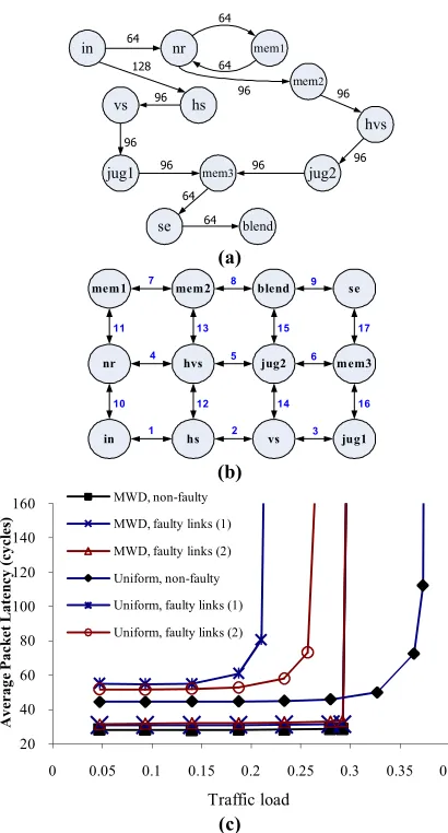
4. 3. Adaptive Routing Algorithm We used different simulations to demonstrate the performance of the Main-RAFT routing algorithm introduced in the work [2]. In the first simulation, a 5×5 NoC is simulated under the uniform traffic pattern in order to compare with the FT_XY3 routing method in addition to examination in different faulty situations. In this simulation, three situations are used: a normal network with no fault and two examples of faulty networks, one with three and another with five faulty links as shown in Figure 5a. As depicted in Figure 5b, under low traffic loads, the impact of faults on the average latency is negligible for Main-RAFT. In addition, the saturation points of the normal, three-fault and five-fault NoCs using Main-RAFT are equal to 0.31, 0.25 and 0.24 of maximum traffic load, respectively. Moreover, Figure 5b shows the better performance of the adaptive method, Main-RAFT, compared to the deterministic method, FT_XY3.
In the second simulation, a 4×4 NoC including VOPD blocks is used in which four nodes are spare nodes (Figure 6a). Figure 6a also shows the remapping process when two routers fail in this network. Figure 6b demonstrates the load-latency diagrams under the uniform and VOPD traffic patterns for non-faulty and faulty NoCs using the RAFT2 routing algorithm. Figure 6b shows that the network performance under VOPD does not differ so much for faulty and non-faulty networks.
(a)
(b)
(c)
Figure 4. (a) The VOPD block diagram, (b) two faulty link scenarios: 2 faults (1) and 3 faults (2) and (c) average packet
latencies in the normal and faulty 3×4 NoCs
(a)
AC/DC
prediction iQuant. IDCT Up
sampling VOP
reconstr.
VOP Memory Padding
ARM Demux
Var length
decoder Run length decoder Inverse scan
Stripe memory 362 362 362
70
16
16
16 313
94 500 300 313
49 27
357 353
ID C T A R M
iQ uan t
A C /D C pred.
Up Sa m p.
Inverse scan
VO P m em ory
VO P reconst.
R un leng th decoder
Pa dding
S tripe m em ory
V ar leng th decoder (1)
(1)
(2)
(2)
(2)
×
×
×
×
20 40 60 80 100 120 140 160
0 0.04 0.08 0.12 0.16 0.2 0.24 0.28
A
ver
ag
e
P
ac
ke
t L
at
en
cy
(
cy
cl
es)
Traffic load
VOPD, non-faulty VOPD, 2 faulty links
VOPD, 3 faulty links Uniform, non-faulty
Uniform, 2 faulty links Uniform, 3 faulty links
×
× ×
×
×
(1) (1) (2)
(2) (1)
(b)
Figure 5. (a) Two faulty link scenarios: three faulty links (1) and five faulty links (2) and (b) average packet latencies in the
normal and faulty 5×5 NoCs
(a)
(b)
Figure 6. (a) Remapping of VOPD faulty blocks in a 4×4 NoC and (b) average packet latencies in the normal and faulty
4×4 NoCs
In the third simulation, a 3×4 NoC is used under the uniform and MWD traffic patterns. The communication task graph (CTG) for MWD including the required bandwidth for each link in mega bytes per second is depicted in Figure 7a. In addition, Figure 7b shows a 3×4 NoC with the numbered links and MWD blocks mapped on it. In this simulation, two faulty networks are used in addition to the network with no fault. In the
first faulty network, faulty links (1) include the links 2, 8 and 14, and in the second faulty network, faulty links (2) include the links 3, 5, 7 and 9. As shown in Figure 7c, the impact of faults on the average packet latency is much smaller under MWD than the uniform traffic similar to Figure 4c. In other words, the Main-RAFT performance is much better under this real application than the uniform pattern.
(a)
(b)
(c)
Figure 7. (a) CTG for MWD application, (b) NoC with mapped MWD blocks and (c) average packet latencies in the
normal and faulty 3×4 NoCs
5. CONCLUSION
In this paper, two types of low-cost routing algorithms are evaluated and compared as fault-aware methods used in NoCs. These methods are deterministic or adaptive, but both are multi-level, distributed, scalable and reconfigurable routing algorithms. The reliability and performance evaluation were the goals of this paper. For reliability evaluation, we used two analytical methods as precise approaches to estimate the NoC reliability. However, for performance evaluation we
20 50 80 110 140 170 200 230 260
0 0.05 0.1 0.15 0.2 0.25 0.3 0.35
A
ver
ag
e
P
ac
ke
t
L
at
en
cy
(
cy
cl
es)
Traffic load
Normal non-faulty,Main-RAFT 3 faulty links,Main-RAFT
5 faulty links,Main-RAFT Normal non-faulty,FT_XY3
3 faulty links,FT_XY3
ID C T A R M
iQ uant
A C /D C pred.
U p S a m p .
I n v e r se s c a n
V O P m e m o r y
V O P re c o n s t .
R un le n g th d e co d e r
P a d d ing
Str ip e m e m o r y
V a r le n g t h d e c o d er
×
N e w R un le n g th N e w
A R M
×
× × ×
× × ×
×
0 40 80 120 160 200 240 280
0 0.05 0.1 0.15 0.2 0.25 0.3 0.35 0.4
A
ver
ag
e
P
ac
ke
t L
at
en
cy
(
cy
cl
es)
Traffic load
VOPD, non-faulty VOPD, two faulty nodes Uniform, non-faulty Uniform, two faulty nodes
in nr
vs
mem3
hs
hvs mem1
mem2
jug2 jug1
se blend
64
64 64
96 128
96
96
96 96
64 64
96 96
mem1 mem2
nr
in
hvs
hs
blend
jug2
vs
se
mem3
jug1
1 2 3
4 5 6
7 8 9
10 11
12 13
14 15
16 17
20 40 60 80 100 120 140 160
0 0.05 0.1 0.15 0.2 0.25 0.3 0.35 0.4
A
ver
ag
e
P
ac
ke
t L
at
en
cy
(
cy
cl
es)
Traffic load MWD, non-faulty
MWD, faulty links (1) MWD, faulty links (2)
Uniform, non-faulty
used appropriate simulations to show the network performance of the mentioned methods in different faulty and non-faulty networks. Furthermore, we compared the results with that of the basic non-fault-tolerant routing algorithms.
6. REFERENCES
1. Valinataj, M., Mohammadi, S. and Safari, S., "Fault-aware and reconfigurable routing algorithms for networks-on-chip", IETE
Journal of Research, Vol. 57, No. 3, (2011), 215.
2. Valinataj, M., Mohammadi, S., Plosila, J., Liljeberg, P. and Tenhunen, H., "A reconfigurable and adaptive routing method for fault-tolerant mesh-based networks-on-chip",
AEU-International Journal of Electronics and Communications,
Vol. 65, No. 7, (2011), 630-640.
3. Grecu, C., Pande, P., Ivanov, A. and Saleh, R., "Bist for network-on-chip interconnect infrastructures", in VLSI Test Symposium, Proceedings. 24th IEEE, (2006), 35-41.
4. Raik, J., Ubar, R. and Govind, V., "Test configurations for diagnosing faulty links in noc switches", in Test Symposium,. ETS'07. 12th IEEE European, (2007), 29-34.
5. Valinataj, M., Mohammadi, S. and Safari, S., "Reliability assessment of networks-on-chip based on analytical models",
Journal of Zhejiang University Science A, Vol. 10, No. 12,
(2009), 1801-1814.
6. Sajjadi-Kia, H. and Ababei, C., "A new reliability evaluation methodology with application to lifetime oriented circuit design", (2013).
7. Shafik, R. A. and Al-Hashimi, B. M., "Reliability analysis of on-chip communication architectures: An mpeg-2 video decoder case study", Microprocessors and Microsystems, Vol. 35, No. 2, (2011), 285-296.
8. Yamamoto, A. Y. and Ababei, C., "Unified system level reliability evaluation methodology for multiprocessor
systems-on-chip", in Green Computing Conference (IGCC), International, IEEE. (2012), 1-6.
9. Bhardwaj, D., Jain, S. and Singh, M. P., "Estimation of network reliability for a fully connected network with unreliable nodes and unreliable edges using neuro optimization", International
Journal of Engineering-Transactions A: Basics, Vol. 22, No.
4, (2009), 317.
10. Lehtonen, T., Liljeberg, P. and Plosila, J., "Fault tolerance analysis of noc architectures", in Circuits and Systems,. ISCAS. International Symposium on, IEEE. (2007), 361-364.
11. Refan, F., Alemzadeh, H., Safari, S., Prinetto, P. and Navabi, Z., "Reliability in application specific mesh-based noc architectures", in On-Line Testing Symposium,. IOLTS'08. 14th IEEE International, (2008), 207-212.
12. Valinataj, M., Liljeberg, P. and Plosila, J., "A fault-tolerant and hierarchical routing algorithm for noc architectures", in NORCHIP, IEEE. (2011), 1-6.
13. Li, M., Zeng, Q.-A. and Jone, W.-B., "Dyxy: A proximity congestion-aware deadlock-free dynamic routing method for network on chip", in Proceedings of the 43rd annual Design Automation Conference, ACM. Vol., No., (2006), 849-852. 14. Flich, J. and Duato, J., "Logic-based distributed routing for
nocs", Computer Architecture Letters, Vol. 7, No. 1, (2008), 13-16.
15. Mejia, A., Palesi, M., Flich, J., Kumar, S., López, P., Holsmark, R., and Duato, J., "Region-based routing: A mechanism to support efficient routing algorithms in nocs", Very Large Scale
Integration (VLSI) Systems, IEEE Transactions on, Vol. 17,
No. 3, (2009), 356-369.
16. Jalabert, A., Murali, S., Benini, L. and De Micheli, G., "×
pipescompiler: A tool for instantiating application specific networks on chip", in Design, Automation and Test in Europe Conference and Exhibition, Proceedings, IEEE. Vol. 2, (2004), 884-889.
17. Chiu, G.-M., "The odd-even turn model for adaptive routing",
Parallel and Distributed Systems, IEEE Transactions on, Vol.
11, No. 7, (2000), 729-738.
Reliability and Performance Evaluation of Fault-aware Routing Methods
for Network-on-Chip Architectures
RESEARCH NOTE
M. Valinataj
School of Electrical and Computer Engineering, Babol University of Technology, Babol, Iran
P A P E R I N F O
Paper history:
Received 21 November 2012 Received in revised form 30 July 2013 Accepted 07 November 2013
Keywords: Network-on-Chip Routing Algorithm Reliability Performance Fault
Analytical Model
هﺪﯿﮑﭼ
ﻝﺎﮑﺷﺍﻩﺯﻭﺮﻣﺍ ﺎﻫ
ﯽﺑﺍﺮﺧ ﻭ ﻪﺑ ﺎﻫ ﻪﻧﺎﻣﺎﺳﺭﺩﻩﮋﻳﻭ ﻪﻧﺎﻣﺎﺳﺪﻨﻧﺎﻣﻩﺪﻴﭽﻴﭘ ﯼﺎﻫ
ﯼﺎﻫ ﯼﻭﺭ ﻪﮑﺒﺷﺮﺑﯽﻨﺘﺒﻣﻪﺷﺍﺮﺗ ﯼﻭﺭ
ﺮﻃﺎﺧﻪﺑﻪﺷﺍﺮﺗ
ﺐﻴﺳﺁﺶﻳﺍﺰﻓﺍ ﻩﺭﺍﺰﻓﺍﻩﺯﺍﺪﻧﺍﺶﻫﺎﮐﻭﯼﺮﻳﺬﭘ
ﺪﻨﺘﺴﻫﺶﻳﺍﺰﻓﺍﻝﺎﺣﺭﺩ،ﺎﻫ .
ﻢﺘﻳﺭﻮﮕﻟﺍ،ﺮﮕﻳﺩﻑﺮﻃﺯﺍ ﻞﻤﺤﺗﯽﺑﺎﻳﺮﻴﺴﻣﯼﺎﻫ
ﺬﭘ ﺮﻳ
ﻝﺎﮑﺷﺍﻞﻤﺤﺗﺭﺩ ﯽﻤﻬﻣﺶﻘﻧﻝﺎﮑﺷﺍ ﻪﮑﺒﺷﺮﺑﯽﻨﺘﺒﻣﻪﻧﺎﻣﺎﺳﮏﻳﻥﺎﻨﻴﻤﻃﺍﺖﻴﻠﺑﺎﻗﺩﻮﺒﻬﺑﻭﯽﻤﺋﺍﺩﯼﺎﻫ
ﯼﻭﺭ ﺪﻧﺭﺍﺩﻪﺷﺍﺮﺗ . ﻦﻳﺍ
ﻢﺘﻳﺭﻮﮕﻟﺍﯽﻠﺻﺍﻩﻭﺮﮔﻭﺩﯽﻳﺁﺭﺎﮐﻭﻥﺎﻨﻴﻤﻃﺍﺖﻴﻠﺑﺎﻗﻦﻴﻴﻌﺗﯼﺍﺮﺑﯽﺑﺎﻳﺯﺭﺍﮏﻳﻪﻟﺎﻘﻣ ﻢﺘﻳﺭﻮﮕﻟﺍ،ﻝﺎﮑﺷﺍﺯﺍﻩﺎﮔﺁﯽﺑﺎﻳﺮﻴﺴﻣﯼﺎﻫ
ﯼﺎﻫ
ﻢﺘﻳﺭﻮﮕﻟﺍﻭﯽﻌﻄﻗ ﺩﻪﮐﯽﻘﻴﺒﻄﺗﯼﺎﻫ
ﯼﺭﺎﻤﻌﻣﺭ ﻪﮑﺒﺷﯼﺎﻫ ﯼﻭﺭ ﯽﻣﻩﺩﺎﻔﺘﺳﺍﻪﺷﺍﺮﺗ ﯽﻣﻪﺋﺍﺭﺍ،ﺪﻧﻮﺷ
ﺪﻳﺎﻤﻧ . ﯽﺳﺭﺮﺑﺖﺤﺗﯼﺎﻬﺷﻭﺭ
ﻞﻤﺤﺗﯼﺍﺮﺑ ﯽﻣﺢﻄﺳﺮﻫﻪﮐﻩﺩﻮﺑﯽﺤﻄﺳﺪﻨﭼﺭﺎﺘﺧﺎﺳﮏﻳﯼﻭﺎﺣﻝﺎﮑﺷﺍﯼﺮﻳﺬﭘ ﺩﺮﻴﮔﺭﺍﺮﻗﯽﺑﺎﻳﺯﺭﺍﺩﺭﻮﻣﻪﻧﺎﮔﺍﺪﺟﺪﻧﺍﻮﺗ
. ﯼﺍﺮﺑ
ﻗﯽﺒﻴﮐﺮﺗﯼﺎﻬﻟﺪﻣﯼﺎﻨﺒﻣﺮﺑﯽﻠﻴﻠﺤﺗﺩﺮﮑﻳﻭﺭﮏﻳ،ﺎﻬﺷﻭﺭﻦﻳﺍﻥﺩﻮﺑﺮﺛﺆﻣﻥﺩﺍﺩﻥﺎﺸﻧ ﻥﺎﻨﻴﻤﻃﺍﺖﻴﻠﺑﺎﻗﻦﻴﻤﺨﺗﯼﺍﺮﺑﻥﺎﻨﻴﻤﻃﺍﺖﻴﻠﺑﺎ
ﯽﻣﺩﺎﻬﻨﺸﻴﭘ ﻢﺘﻳﺭﻮﮕﻟﺍﺮﺛﺍﻢﻴﻧﺍﻮﺘﺑﺎﺗﻢﻴﻫﺩ ﻪﮑﺒﺷﯽﻠﮐﻥﺎﻨﻴﻤﻃﺍﺖﻴﻠﺑﺎﻗﯼﻭﺭﺮﺑﺍﺭﻝﺎﮑﺷﺍﺯﺍﻩﺎﮔﺁﯽﺑﺎﻳﺮﻴﺴﻣﯼﺎﻫ
ﯼﻭﺭ ﻦﻴﻴﻌﺗﻪﺷﺍﺮﺗ
ﻢﻴﻨﮐ . ﻝﺎﺣﻦﻳﺍﺎﺑ ، ﻢﺘﻳﺭﻮﮕﻟﺍﻦﻳﺍﯽﻳﺁﺭﺎﮐﯽﺑﺎﻳﺯﺭﺍﯼﺍﺮﺑ ﻪﻴﺒﺷ،ﺎﻫ
ﯼﺯﺎﺳ ﺑﺭﺎﮐﻉﻮﻧﻦﻳﺪﻨﭼﻖﺑﺎﻄﻣﺍﺭﯽﻋﻮﻨﺘﻣﯼﺎﻫ ﻡﺎﺠﻧﺍﻒﻠﺘﺨﻣﺩﺮ
ﻩﺩﺍﺩ ﻢﻳﺍ
.
![Figure 1. (a) The old paths (dashed lines) broken by a horizontal and vertical faulty link are restored by the new paths (solid lines) based on the previous work [1] and (b) the old paths and the new paths based on the work [2]](https://thumb-us.123doks.com/thumbv2/123dok_us/233225.2017926/3.595.58.283.458.710/figure-dashed-broken-horizontal-vertical-faulty-restored-previous.webp)
![TABLE 1. Reliabilities obtained by different deterministic routing algorithms [1] for the path shown in Figure 3](https://thumb-us.123doks.com/thumbv2/123dok_us/233225.2017926/4.595.308.544.122.193/table-reliabilities-obtained-different-deterministic-routing-algorithms-figure.webp)
![TABLE 2. Reliabilities obtained by different adaptive routing algorithms [2,12] for the 3×4 NoC](https://thumb-us.123doks.com/thumbv2/123dok_us/233225.2017926/5.595.307.543.122.193/table-reliabilities-obtained-different-adaptive-routing-algorithms-noc.webp)