A MODEL FOR THE DETERMINATION OF THE CRITICAL BUCKLING LOAD
OF SELF-SUPPORTING LATTICE TOWERS
M. E. Onyia
1,*and M. C. Nwosu
21, 2
D
EPARTMENT OFC
IVILE
NGINEERING,
U
NIVERSITY OFN
IGERIA,
N
SUKKA.
E
NUGUS
TATE,
NIGERIA.
Email addresses:
1[email protected],
2[email protected]
ABSTRACT
Most tall columns under axial load fail by buckling. Considering the widespread use of this type of structure and the critical role it plays in service delivery, its failure will result in possible loss of lives and property and disruption of services. It is therefore necessary to evolve alternative methods of determination of the buckling load of self-supporting lattice towers. This paper therefore proposes a simple model for the determination of the critical buckling load of self- supporting lattice towers. The proposed model idealizes the lattice tower as an equivalent solid
beam-column whose cross-sectional-dimensions are the unknowns to be determined. The expression is proposed by the model for the critical buckling load of self- supporting lattice tower, whose equivalent solid beam-column has a dimension b at its free end. The results obtained using the proposed model are shown to be acceptable, with a percentage difference of about0.036% when compared with results obtained using conventional methods.
Keywords: Lattice Tower, Beam-column, Buckling load, Truss.
1. INTRODUCTION
Towers are tall steel frame structures used for different purposes such as installation of equipment for telecommunication, radio transmission, satellite reception, power transmission, air traffic control, television transmission, flood lights, meteorological measurements, etc. Lattice towers act as cantilever trusses since they are usually clamped at the base. They resist wind and seismic loads, as well as vertical load from self-weight and equipment installed on the tower, [1].
Lattice towers can be analysed as vertical trusses which resist wind load by cantilever action, [2]. Towers are subjected to both vertical and horizontal forces, the significant horizontal forces being as a result of wind action on the vertical part of the tower, [3]. A column buckling analysis consists of determining the maximum load a column can support before it collapses. The critical load is the greatest load that will not cause lateral deflection (buckling) of the column. For loads greater than the critical load, the column will deflect laterally. The critical load puts the column in a state of unstable equilibrium, [4, 16]. A load beyond the critical will cause the column to fail by buckling. For long columns, failure by buckling has nothing to do with
material yield. It is instead governed by the column’s stiffness, both material and geometric, [5, 6].
This paper proposes a model for the determination of the critical buckling load of self-supporting lattice towers by replacing the actual tower with an equivalent beam-column.
2. STRUCTURAL MODELLING
The structural model is a solid beam-column of exactly the same height and lateral deflection curve as the actual self-supporting lattice tower. The cross sections of both the self-supporting tower and the equivalent structure should be similar but must not be equal in dimensions. (Figure 1).
Since the self-supporting truss tower is normally prevented from movement at its base, the equivalent solid beam-column is analysed as a linearly-varying cantilever beam, [7]. The equivalent beam-column is assumed to have the same values of lateral deflection (sway) under the action of the same applied loads at exactly the same points along its length as the self-supporting lattice tower, [8, 9, 10]. The analysis thus considers the failure of the tower structure as a whole, rather than the failure of the individual truss members.
Vol. 37, No. 1, January 2018, pp. 60 – 66 Copyright© Faculty of Engineering, University of Nigeria, Nsukka,
Print ISSN: 0331-8443, Electronic ISSN: 2467-8821
www.nijotech.com
Figure 1: Structural modelling of lattice tower
3. MATHEMATICAL MODELLING
The analysis consists of the following steps
(i) an appropriate structural model (equivalent solid beam-column) that best suits the actual structure (self-supporting lattice tower) under consideration was selected. The model must have exactly the same height and cross-sectional shape as the actual structure.
(ii) an analysis of the actual self-supporting lattice tower with the given dimensions and loadings was performed to determine the numerical values of lateral deflection (sway) along its length. (iii) using the determined deflection values at known
points on the actual structure, the unknown cross-sectional dimensions of the equivalent solid beam-column were determined by equating deflections at the same points along the length of the equivalent structure. Thus, the self-supporting lattice tower and the equivalent solid beam-column have to be analyzed under the action of the same loadings acting at the same points and direction.
(iv) a dynamic analysis of the equivalent solid beam-column was performed to determine its natural vibration frequencies.
3.1 Cross-Sectional Properties of the Equivalent Solid Beam-Column
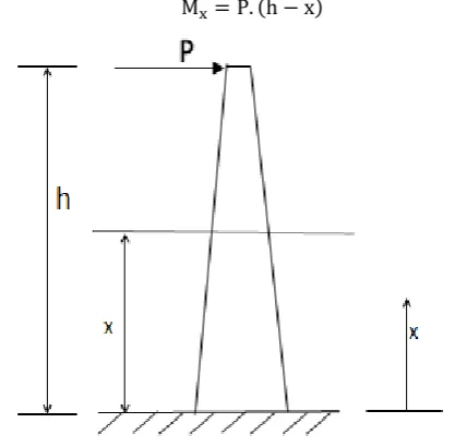
Consider a solid beam-column structure of height h with a linearly-tapering cross-section and fixed at its base, (Fig. 2).
A horizontal force P is applied at its free end. The bending moment along the cantilever solid beam is
. (h ) ( )
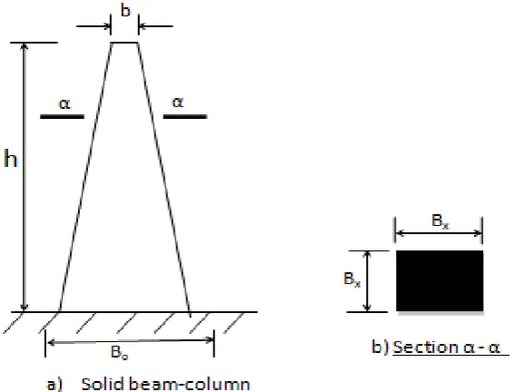
Figure 2: Solid beam-column with linearly-tapering cross-section
From theory of structures, strain energy due to the applied load is, [11]:
∫ d
I ( ) From Castigliano’s theorem, the deflection of the member is expressed as, [11]:
∫ I
d ( ) The linearly-tapering dimension of the beam-column can be expressed as, [7, 12]:
a. c ( ) where BX is the width of the cross-section at any point x
Figure 3: Cross-sectional dimensions of the equivalent beam-column
To determine the values of the constants a and c in Equation (4), we need to consider the boundary conditions of the equivalent beam-column structure under consideration, (Fig.3):
(i) At x = 0 (base), Bx = Bo
(ii) At x = h (top), Bx = b
h (b )
h ( ) The moment of inertia for the equivalent solid beam can be expressed in terms of BX.
Moment of Inertia, I ( )
i.e.
I h (b )
h ( ) Putting Boh = o and b – Bo β
Then the expressions for Bx and Ix can be expressed as
follows:
β
h ( )
I ( β )
h ( ) The strain energy of the equivalent structure is given by Equation (2). Substituting for Mx and Ix in the strain
energy equation gives:
( ) h ∫ (h )
( β ) d ( ) From Castigliano’s theorem, the deflection of the equivalent structure is given by Equation (3). But Mx =
P (h - x) and Ix =
( ) . hus,
h
( ) ∫ I (
)d
i. e. h ∫ (h )
( β ) d ( )
Integrating Equation (10) by partial fractions, we get equation (11)
( ) ( h
β ). [( β ) –
( βh) ( β )
( βh)
( β )
( βh)
( βh)
] ( )
In (11) = Boh and β b – Bo. The proposed model
(i.e. the beam-column) can only be said to be equivalent to the actual self-supporting lattice tower if its deflection curve under the action of the same loading is the same as that of the actual tower, [9, 13]. Therefore, the self-supporting lattice tower should be analyzed statically for deflection along its length and the values at x = h and x = equated to the above
expression for deflection of the equivalent solid beam-column (i.e Equation 11) to determine the unknown values of its cross-section, b and Bo. If the deflection of
the free end (tip) is Y, then putting x = h in (11), and
noting that = Boh and β b – Bo, we get
.
b C ( )
here c h ( )
If the deflection at the middle is Y1/2, then putting x =
in Equation (11), we have that:
( )
, C ( ),
C ( ),
C ( C )
( )
The values of b and are then determined from Equations (12) and (14).
3.2 Beam-Column Differential Equation
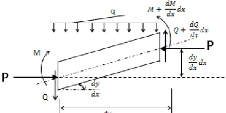
In considering the elastic buckling load of a column, it is necessary to determine the load at which the structure remains in equilibrium in the deformed position. In order to derive the necessary equations, consider an element of a beam-column in the deformed position with the forces acting as shown in Fig.4. It is assumed that during the deformation, the axial load remains in its original direction.
Figure 4: Forces acting on a beam-column in the deformed state
Figure 5: Mode of buckling of a Cantilever beam-column
From vertical equilibrium considerations,
( d
d d ) d
ord
d ( ) Taking moments,
( d
d d ) ( d
d d ) d ( dy d d )
d .d
Ignoring second-order terms, d
d dy d
. . d d
dy
d ( ) Differentiating Equation (17) with respect to x: d
d d
d d y d But from Equation (16),
(d d
d y d )
ut Id y d
hus, d
d ( I d y d )
d y
d ( ) If it is assumed that EI is constant, then Equation (18) can be written as:
Id y d
d y
d ( ) This equation is generally known as the beam-column equation. Note that in a beam-column equation, shear force Q is given by Equation (17) as:
d d
dy
d ( I d y d
dy
d ) ( ) The solution to the beam-column equation,(Equation 19), which is a fourth-order ordinary differential equation with constant coefficients, is given by:
y Cos in C
articular Integral ( ) here
and A to D are constants of
integration. Once the value of q is known, then the particular integral can be determined.
3.3 Buckling Load of Equivalent Beam-Column From Equation (21):
y Cos in C ,
I ( Cos in ) ( )
From Equation (20),
i. e. d d (
Id y d )
dy d
ut I I
hus, Id y d I
dy d
or I (d y d
Substituting for
and
I ( in Cos in Cos C)
I C ( ) Note that there are four constants of integration to be determined. This requires four boundary conditions. For the cantilever beam-column, the boundary conditions are:
(i) Fixed end (base): y and (
)
(ii) Free end (top): = 0 and
y Cos in C y Cos in
or dy
d in Cos C
(dy d )
in Cos C
Hence, C or C I ( Cos in )
, I ( Cos h in h)
or Cos h in h ) I C
, I C or C = 0
Since C = - B, B = 0
Thus, Equation (24) becomes: Cos h in h Or Cos h
As , Cos h
The smallest root is given by h
or , ut
I h ( )
Where Pcr is the uler’s critical load.
This is the elastic buckling (critical) load for a beam-column. For the linearly-tapering beam-column,
I I ( β ) h
h [
( β ) h ]
( β ) h
A beam-column will, if not restrained in any particular place, buckle about an axis with the least value of second moment of area, [13, 17].
At the free end, x=h
β h (b )h bh
h (bh) b h h
b
h ( )
3.4 Buckling of Self-supporting Lattice Tower
The stiffness of the cantilever beam-column is given by, [11]:
I
h ( ) where h is the height of the column
I h
h
( )
The Buckling load of the cantilever column is given by
Equation (25) as:
.
. ut
. For the four-legged self-supporting Lattice tower, [14, 15]:
C (
h ) (
h) C h
( ) where C = 0.04008
4. RESULTS AND DISCUSSION
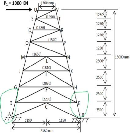
The self-supporting lattice tower in Fig. 6is subjected to a horizontal load P1 = 1000KN at its free end (Point U).
The truss is assumed to be pin-jointed. The tower, being self-supporting, is assumed to be rigidly fixed at its base (Points A and B).
Figure 6: Self-supporting lattice tower under load.
The tower has the following properties: (i) Density = 7850 kg/m3
(ii) oung’s odulus, 6 KN/m2
Details of the lengths, cross-sectional areas and orientation of the truss members are shown in Table 1. From Table2,
(i) Deflection at the free end (tip), (x =h) = Y1 =
0.59133378m
(ii) Deflection at mid-height, (x = ) = Y1/2 =
Table 1: Properties of Truss Members
S/
N MEMBER (degrees) ANGLE LENGTH (m)
CROSS-SECTIONAL
AREA (m2)
S/N MEMBER (Degrees) ANGLE LENGTH (m)
CROSS-SECTIONAL
AREA (m2)
1 UV 0 1.3 0.000225 21 LJ 249.8 2.664 0.00512
2 US 267.94 1.251 0.000225 22 LK 290.2 2.664 0.00512
3 VS 223 1.836 0.000225 23 JI 0 0.92 0.00512
4 VT 272.06 1.251 0.000225 24 KI 180 0.92 0.00512
5 ST 0 1.39 0.000225 25 JG 267.94 2.502 0.00512
6 SR 319 1.903 0.000744 26 KH 272.06 2.502 0.00512
7 TR 272.06 1.251 0.000744 27 IG 248 2.696 0.00512
8 SQ 267.94 1.251 0.000744 28 IH 292 2.696 0.00512
9 QR 0 1.48 0.000744 29 GF 0 1.01 0.00512
10 QO 267.94 1.251 0.000744 30 HF 180 1.01 0.00512
11 RO 230.66 1.972 0.00151 31 GD 267.94 2.502 0.00808
12 RP 272.06 1.251 0.0028 32 HE 272.06 2.502 0.00808
13 OP 180 1.57 0.0028 33 FD 246.25 2.731 0.00512
14 ON 322.26 2.042 0.0028 34 FE 293.75 2.731 0.00512
15 PN 272.06 1.251 0.0028 35 DC 0 1.1 0.00512
16 OM 267.94 1.251 0.00512 36 EC 180 1.1 0.00512
17 ML 0 0.83 0.00512 37 DA 267.94 2.502 0.00808
18 NL 180 0.83 0.00512 38 EB 272.06 2.502 0.00808
19 MJ 267.94 2.502 0.00512 39 CA 244.55 2.769 0.00512
20 NK 272.06 2.502 0.00512 40 CB 295.45 2.769 0.00512
From Equation (13), c . m
From Equations (15),
. , . , . , .
Therefore Equation (14) becomes:
0.0152 Bo12 – 0.0382Bo8 – 0.003797Bo4 + 0.004578 = 0
Using Newton-Raphson method, Bo = 0.750852 m
Substituting in Equation (12), b . m
Table 2 gives the results of the deflection analysis of the self-supporting lattice tower.
Table 2 – Deflection Values for Self-supporting Lattice Tower
S/N Joint Height from base (m) Deflection (m)
1 U 15.00 0.59133378
2 S 13.75 0.390101219
3 Q 12.50 0.292947928
4 O 11.25 0.19851868
5 M 10.00 0.146828164
6 J 7.50 0.073638858
7 G 5.00 0.029030528
8 D 2.50 0.004289548
9 A 0.00 0.00
a) Critical Buckling Load of the Equivalent Beam
The critical buckling load of the equivalent beam is given by Equation (26). So Pcr = 835.89kN
b) Critical Buckling Load of the Lattice Tower
From Table 2,
he deflection of the free end, Δu = 0.59133378m
Force applied at the free end, Fu = 1000 KN
Hence, stiffness of the structure, K = = 1691.092296
m⁄
For the linearly-tapering cantilever tower structure, the critical buckling load is given by Equation (29) where C = 0.04008 so Pcr = 836.19kN. The summary of the results is presented in Table 3. The pin-jointed self-supporting lattice tower shown in Fig. 6 was analysed using both the proposed model and conventional method. The tower is made of steel with oung’s odulus of elasticity 6 KN/m2 and
density = 7850 kg/m3. The tower, being
self-supporting, is assumed to be rigidly fixed at its base. The properties of the tower are given in Table 1. The results of the deflection analysis of the given lattice tower are displayed in Table 2.The deflection values of the tower are used to obtain the unknown dimensions (b and Bo) of the model structure, which are in turn
deployed in the formulation of the model expression for the computation of the critical buckling load (i.e Equation 26).
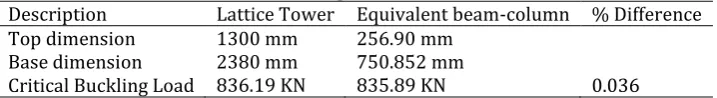
Table 3 – Comparison of Results
Description Lattice Tower Equivalent beam-column % Difference
Top dimension 1300 mm 256.90 mm
Base dimension 2380 mm 750.852 mm
Critical Buckling Load . . 0.036
5. CONCLUSIONS
An expression for the computation of the critical buckling load of self-supporting lattice towers, based on a proposed equivalent solid beam model, was
derived in this work, ( ) where b is a
dimension of the equivalent beam and h is the height of the lattice tower). The equivalent beam was analysed as a cantilever structure subjected to the same load as the actual self-supporting lattice tower. A comparison of the critical buckling load values of the actual lattice tower and the proposed model shows a marginal percentage difference of 0.036%, which is acceptable. As can be observed from Table 3, the proposed model also gives a lower-bound value of the critical buckling load. This is a welcome safeguard against failure by buckling, since it is obviously safer to use the lower value of the critical buckling load as the basis of structural design. The derived model expressions can also be easily modified to analyze towers of different cross-sectional shapes, such as circular and triangular-shaped towers.
6. REFERENCES
[1] Agarwal, S. K., “Wind effect on Structures”, llied Publishers Ltd, 1997.
[2] AbdulMuttalib, I. S. “ nalysis and Optimum esign of Self-supporting teel Communication o er”,
Journal of Engineering, Volume 19, No. 12, pp. 1673 – 1687, 2013.
[3] Khedr, M. A. and McClure, G. “ implified ethod for Seismic Analysis of Lattice Telecommunication o ers”, Canadian Journal of Civil Engineering, Vol. 27, No. 3, pp. 533 – 542, 2000.
[4] Jones, R.M. “Buckling of Bars, Plates and Shells”, CRC., 2007.
[5] Thompson, J. M. T., Hunt, G.W. “A General Theory of Elastic Stability”, Wiley., 1973
[6] Zaccaria, D., Bigoni, D., Noselli, G., Misseroni, D. “ tructures uckling nder ensile ead Load”,
Proceedings of the Royal Society A., Vol. 467, 2011.
[7] Bansal, R. K. “Analysis of Uniformly-tapering Rectangular Bar”, te tbook of trength of Materials, 4th Edition, Laxmi Publications Ltd,
India, ESM: 0598-535, 2010.
[8] Ghodrati, A. G. and Mossah, S. R. “ eismic Response of 4-legged Self-supporting elecommunication o ers”, International Journal of Engineering. Transactions B: Applications Volume 20, No. 2, 2007.
[9] Kang W., Albermani F., Kitipornchai S. and Lam H. “ odelling and nalysis of Lattice o ers With ore ccurate odels”, Advanced Steel Construction, Vol. 3, No. 2 2007..
[10] Mohammadi, S. and Hassanirad, A. “ pplied and Theoretical Cantilever Beam Free-Vibration nalysis”, World Academy of Science, Engineering and Technology, Vol. 61, 2012.
[11] hatt, . and elson, H. .: “ arshall & elson’s Structures”, Longman ingapore ublishers, 1994.
[12] Jithesh, R. and Vijaya S. “ nalysis of Telecommunication Tower Subjected to Seismic and Wind Loading”, International Journal of Advancement in Engineering Technology, Management and Applied Sciences, Vol. 1, Issue 2, pp. 67 – 69, 2014
[13] Jackman, D. E., “Lattice Transmission Tower Analysis”, merican ociety of ngineers. 2002.
[14] Abermani, F. G. A. and Kitipornchai, S. (2003): “ umerical imulation of tructural ehaviour of ransmission o ers”, Thin-Walled Structures, Volume 41, Issues 2-3, ISSN : 0263-8231
[15] Murty, K. S. “ ynamic Response of Lattice o ers and Guyed asts”, American Society of Civil Engineers, 2001.
[16] Osadebe, . . and ze, J.C., “Comparative tudy of Vlasov and Euler Instabilities of Axially Compressed Thin- alled o Columns”, Nigerian Journal of Technology, Volume 29, No. 1, 2010