http://www.sciencepublishinggroup.com/j/ijsts doi: 10.11648/j.ijsts.20170502.11
ISSN: 2330-7412 (Print); ISSN: 2330-7420 (Online)
Controller Design for Three-Mass Resonant System Based
on Polynomial Method
Ghazanfar Shahgholian
Department of Electrical Engineering, Najafabad Branch, Islamic Azad University, Najafabad, Iran
Email address:
To cite this article:
Ghazanfar Shahgholian. Controller Design for Three-Mass Resonant System Based on Polynomial Method. International Journal of Science, Technology and Society. Vol. 5, No. 2, 2017, pp. 13-25. doi: 10.11648/j.ijsts.20170502.11
Received: March 29, 2017; Accepted: April 12, 2017; Published: May 2, 2017
Abstract:
The mechanical system in the industrial electrical drives can be modelled by a multi-mass system. Torsional vibration suppression and attainment of robustness in motion control systems is a requisite in industry applications. In this paper, the system that is three-mass system is considered. A speed control method based on polynomial method introduced to imple-mentation of torsional vibration is proposed. The effectiveness of the proposed controller is demonstrated by transfer function analysis and simulation results. The simulation results show that the proposed controller improves dynamic performance and suppresses torsional vibration of three-mass resonant system.Keywords:
Three-Mass System, Speed Control, Polynomial Method, Transfer Function1. Introduction
In industrial motor drive systems, a shaft torsional vibrati-on is often generated in which a motor and load are cvibrati-onnec- connec-ted via a flexible shaft [1-3]. A mechanical system composed of some masses connected with flexible shafts such as steel rolling mills, variable-speed wind turbine, industrial robot, ele-vator systems and so on, is called multi-mass resonant sys-tem [4, 5]. This simplified approach has been used in different industrial applications [6-8]. Vibration suppression and high speed response control in motion control system is an important problem in industry applications [9-11]. Control problems of a multi-mass system is especially difficult when not all system variables are measurable, which happens very often in industrial applications [12, 13].
Several references in technical literature can be found on the application of control methods to improvement perf-ormance of the multi-mass [14-16]. A vibration-suppression control method for both two- and three-mass system is prop-osed in [17], which uses controller with three elements: the disturbance observer, the imperfect derivative filter, and the feedback gain. In order to reduce the computational comp-lexity, the model predictive control for high-performance sp-eed control and torsional vibration suppression in the elastic
three-mass drive system is described in [18]. An algorithm to design a speed control strategy of a two-mass resonant syste-m by a integral–proportional-derivative (PID) controller bas-ed on the response frequency and the response step is deve-loped in [19]. In order to have sufficient damping, in [20] thr-ee different controller base on PID controller are designed for the speed control of a two-mass system using a normalized model and polynomial method. The PID, PID-P and modify PID controllers in order to control torque of a two-mass reso-nant system is presented in [21], which the pole-placement controller such as coefficient diagram method and integral of time multiplied by absolute error is used to assign closed-loop poles of the system characteristic equation.
2. Mathematical Model of Three-Mass
System
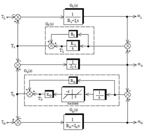
A motor drive system is composed of a motor connected to a load machine through a flexible shaft. Simplified model of the three-inertia torsional system (motor, load and gear) is shown in Figure 1 [24]. Here ωM is motor speed, ωL is load
speed, TS is shaft torsional torque, TG is gear torque and ωG is
gear speed. The control input is motor torque (TM) and the
input disturbance is load torque (TL). The speed motor is the
measurable, but we have no sensor to measure load speed. The system parameters used for study and simulation are listed in Table I [25, 26].
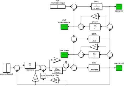
The block diagram of the three-mass system is show in Figure 2. The gear backlash is simplified as a nonlinear element with backlash angle band [-δ, + δ] and elastic coeffic-ient KG [27, 28]. The state equation of the three-mass torsio-nal system is expressed as [29, 30]:
'
1 1
( S) S
L L
L G S L
L L L L L
B B d B
T T dt J J J J J
ω = − + ω + ω + −
(1)
'
1 1
( G) G
M M
M G G M
M M M M M
B B
d B
T T
dt J J J J J
ω = − + ω + ω − +
(2)
' '
1 1
( )
G
S G G G G S L G M
C C
d
T T B B B B dt J J
ω = − + − + ω + ω + ω
(3)
'
( )
S
S L G
dT K
dt = −ω +ω (4)
'
( )
G
G M G
dT K
dt = ω −ω (5)
where JM, JL, JG, BM, BL, BG, KG, KS are the motor inertia, the
load inertia, the gear inertia, the motor viscous damping coefficient, the load viscous damping coefficient, the gear damping coefficient, the gear stiffness, and the shaft stiffness, respectively.
Figure 1. Simplified model of three-mass torsional system
Table 1. Parameters Used in the Study of Three-Mass System.
Parameters Symbol Value
motor inertia JM 0.0641 Kgm2
motor damping coefficient BM 0
load inertia JL 0.0523 Kgm2
load damping coefficient BL 0
shaft stiffness KS 242 Nm/rad
shaft damping coefficient BS 0.1 Nm-s/rad
gear stiffness KG 2000 Nm/rad
gear damping coefficient BG 0.2 Nm-s/rad
gear inertia JC 0.0868
resonance frequencies ωr1,ωr2 77.98, 235.75 rad/s
anti-resonance frequencies ωa1,ωa2 63.52, 162.55 rad/s
Figure 2. Block diagram of the nonlinear three-mass system.
' '
( )
( )
S S S G L
G G G M G
T T B T T B
ω ω ω ω = − − = − −
(6)
The characteristic equation of open loop system are given by:
5 4 3 2
4 3 2 1 0
( )
o s s p s p s p s p s p
∆ = + + + + + (7)
By varying the operating point, the coefficient parameter values p4 through p0 also vary. A necessary condition for
stability of the system is that all the roots in characteristic equation have a negative real part. By forbear from the value of the damping coefficients, p0, p2 and p4 are zero. The p1 and
p3 are given by:
1 S G (1 L M)
L M C
K K J J p
J J J
+
= + (8)
3 S (1 L) G(1 M)
L C M C
K J K J p
J J J J
= + + + (9)
3. Open-Loop Three-Mass System
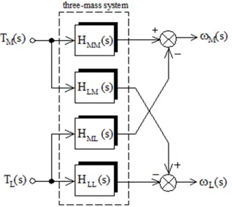
Let a two-input two-output process be represented by the block diagram shown in Figure 3. The three-mass system can be represented in the following matrix form [31, 32]:
( ) ( ) ( ) ( )
L LL LM L
M ML MM M
H s H s T H s H s T
ω ω − = −
(10)
The transfer function of the open-loop three-mass system are given by:
Figure 3. Two-input and two-output of the system.
2 ( ) MM
a
H s
b a c =
+ (11)
2 ( ) LL
a
H s
b a c =
+ (12)
2
( ) ( )
LM ML
b
H s H s
b a c
= =
+ (13)
where the coefficient a, b and c are given by:
( )[ ( ) ] 1 ( ) ( ) ( ) ( ) ( ) ( ) ( ) ( )[ ( ) ] 1 ( ) ( ) ( )
S G C
L C S G
G S
C S G
S G C
M C S G
G s G s J s a
G s J s G s G s G s G s
b
J s G s G s
G s G s J s c
G s J s G s G s
− − = + − − = − − − = − − − (14)
The transfer functions of the motor, load, shaft and gear are GM(s), GL(s), GS(s) and GG(s).
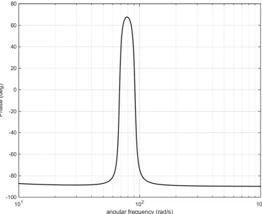
The plot of the open-loop frequency response from the HMM(s) is for two-mass and three-mass are shown in Figs. 4
and 5, respectively. Two high peaks arise for three-mass system in the gain characteristic plot at resonance frequencies ωr1 and ωr2 and two down peak arise at anti-resonance
frequency ωa1 and ωa2. The amount of the attenuation
coeffi-cients are deleted, because the values are very small. Open-loop transfer function between the motor torque and the mot-or speed, which is most impmot-ortant in the closed-loop design can be derived as:
4 2 0 4 2 1 1 ( ) [ ( ) ] M MM
M o M
b
S G S
C C L S G
M L C M
b b
H s s
T s J
K K K
J J J K K s
J J J J
ω = = + ∆ + + + (15)
The transfer function can be represented in the form below:
2 2 2 2
1 2
2 2 2 2
1 2 ( ) ( ) ( ) ( ) ( ) a a MM
M r r
s s H s
J s s s
ω ω
ω ω
+ +
=
+ + (16)
where ωr1 and ωr2 are the natural resonance frequencies
respectively corresponding to the shaft resonance and the gear-resonance.
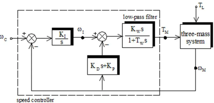
4. Applied Speed Control Structure
( ) ( ) ( ) 1
W I
C P D
W
T s K
G s K K s s T s
= + +
+ (17)
where KW and TW are the gain and time constant of the
washout term while KP, KI and KD are the proportional gain, integral gain, and derivative gain of the damping controller, respectively. KF is the forward gain of the controller. The transfer function of the first-order low-pass filter is KW/
(sTW+1) in the speed controller. The speed command is ωC.
In this I-PD controller, proportional and differential action are worked only on the detected quantity ωM [33]. The
close-loop state space equation can be written as:
d
X A X BU DW dt
Y C X
= + + = (18)
where X is the state vector, Y is the output vector, U is the external or compensated input vector, W is the external disturbance input vector while A, B, C and D are all constant matrices of appropriate dimensions.
With speed controller, the state vector contained seven state variables and the control vector contained command speed as shown below:
' '
[ ]
[ ]
T
L M G S G I X
C
L
X T T T
U
W T
ω ω ω ω
ω = = = (19)
The state variable TM is:
( W)( M)
M X F I P M D
W
K d
T T K K K
T dt
ω
ω ω
= − + + − − (20)
In addition to the five open-loop equation, there are two following equations in closed-loop system:
I
I M I C
d
K K
dt
ω = − ω + ω
(21)
2 2 2
1 W W P W D
X M
X I M
W W W W
K K K K K
dT d
T
dt T T T T dt
ω
ω ω
−
= + − − (22)
Closed-loop transfer functions from speed command to load speed is given by:
( )
( )
(
2)
( )
1 1
C W MM
M s
C W D P MM W
K T H s H s
K K s K s K H s T s
ω ω
= =
Figure 5. Bode diagram of magnitude and phase for three-mass model.
Figure 6. Controlled plant block diagram.
The characteristic equation of the close loop three-mass system equipped with controller is given by:
7 6 5 4 3 2
7 6 5 4 3 2 1 0
( )
c s h s h s h s h s h s h s h s h
∆ = + + + + + + + (24)
0 0
1 0 0
2 1 0 2 0
3 1 2 2 0
4 3 2 2
5 3 2
6
7
( )
( )
( )( )
( )
( )( )
1 ( )
I F
P F I W F W
P W F W P I F D
W F P I D W F W
I F
P W F W D F
M
I P F
W D W F W
M M
D F P
W F W
M M
W
h K K b
h K K b K b K K T
h p K b K K T K b K K b K
h T p K K b K b K b K K T
K K
h p K b K K T K K b
J
K K K
h p T K b K K T
J J
K K K
h K K T
J J
K
h T
=
= + +
= + + + +
= + + + +
= + + + +
= + + + +
= + + +
= + D( W F W) M
K K T
J +
(25)
A good set of controller parameters KF, KW, TW, KP, KD
and KI will yield a good response and results in the vibration
suppression in time domain.
5. Simulation Results
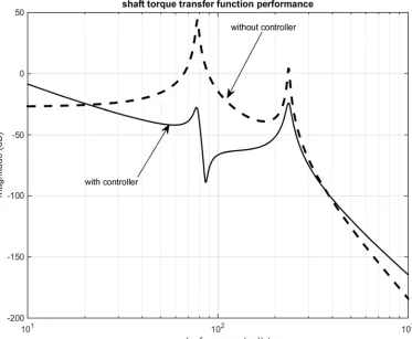
The simulation results of the speed control of the three-mass using the proposed controller will be shown in this section in order to demonstrate the efficiency of the controller. The Simulink model of the system is show in Figure 7. In Figures 8 and 9, the frequency responses considering three-mass system equipped with a speed controller is compared with considering three-mass system without controller. The solid lines show the plots of the closed-loop frequency response from the speed command to motor speed and to shaft torque.
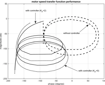
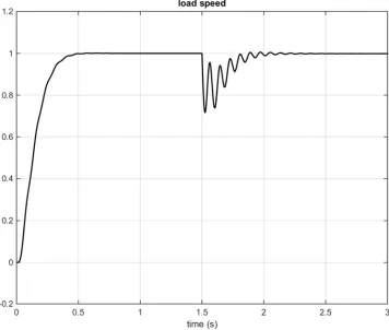
The gain plot of transfer function of motor speed to command speed in three-mass system for two different forward gain is shown in Figure 10. Figures 11 and 12 show the load speed and shaft torsional of the three-mass system with controller. The reference input of 1 rad/s is commanded at t=0, and the 1 Nm disturbance torque is given at t=1.5s. The change of the load speed for three-mass system is show in Figures 13.
Figure 10. Gain-phase plot for two different forward gain and without controller.
Figure 12. Shaft torsional with controller for three-mass system.
6. Conclusion
Vibration suppression and disturbance rejection control in torsional system is an important problem in the future motion control. In this paper a simple speed control method of three-mass torsional system is proposed. The mathematical model of the open-loop and clos-loop was analyzed. The controller selected is an I-PD controller with the gains of which were select base on polynomial method. With control system, a fast response without oscillation can be achieved. The simulation results show that the proposed controller improves dynamic performance and suppresses torsional vibration of three-mass resonant system.
Acknowledgement
This work has been extracted from the research project entitled “Dynamic eigenvalue analysis and simulation of two-mass resonant system with PID controller” in Smart Microgrid Research Center, Najafabad Branch, Islamic Azad University, Najafabad, Isfahan, Iran.
References
[1] J. S. Kim, L. W. Yang, Y. S. Kim, Y. J. Kim, “The vibration suppression control of the two mass resonant system using the H∞ filter”, Proceeding of the IEEE/IECON, Vol.3, pp.1464-1470, Aug./Sep. 1998.
[2] G. Shahgholian, N. Izadpanahi, “Improving the performance of wind turbine equipped with DFIG using STATCOM based on input-output feedback linearization controller”, Energy Equipment and Systems, Vol. 4, No. 1, pp. 65-79, June 2016. [3] G. Shahgholian, J. Faiz, N. Sedri, P. Shafaghi, M. Mahdavian,
“Design and experimental analysis of a high speed two-phase induction motor drive for weaver machines applications”, International Review of Electrical Engineering, Vol. 5, No. 2, pp. 454-461, April 2010.
[4] B. Boukhezzar, H. Siguerdidjane, “Nonlinear control of a variable-speed wind turbine using a two-mass model”, IEEE Trans. on Energy Conversion, Vol. 26, No. 1, pp. 149-162, March 2011.
[5] S. Shimmyo, T. Sato, K. Ohnishi, “Biped walking pattern gene-ration by using preview control based on three-mass model”, IEEE Trans. on Industrial Electronics, Vol. 60, No. 11, pp. 5137-5147, Nov. 2013.
[6] S. Villwock, M. Pacas, “Application of the welch-method for the identification of two- and three-mass-systems”, IEEE Trans. on Industrial Electronics, Vol. 55, No. 1, pp. 457-466, Jan. 2008.
[7] G. Shahgholian, K. Khani, M. Moazzami, “Frequency control in autanamous microgrid in the presence of DFIG based wind turbine”, Journal of Intelligent Procedures in Electrical Technology, Vol. 6, No. 23, pp. 3-12, Autumn 2015.
[8] G. Shahgholian, K. Khani, M. Moazzami, “The Impact of DFIG based wind turbines in power system load frequency control with hydro turbine”, Dam and Hydroelectric
Powerplant, Vol. 1, No. 3, pp. 38-51, Winter 2015.
[9] M. A. Valenzuela, J. M. Bentley, R. D. Lorenz, “Evaluation of torsional oscillations in paper machine sections”, IEEE Trans. on Industrial Applications, Vol. 41, No. 2, pp. 493-501, March/April 2005.
[10] S. H. Mozafarpoor-Khoshrodi, G. Shahgholian, “Improvement of perturb and observe method for maximum power point tracking in wind energy conversion system using fuzzy controller”, Energy Equipment and Systems, Vol. 4, No. 2, pp. 111-122, Autumn 2016.
[11] T. M. O’Sullivan, C. M. Bingham, N. Schofield, “High perfor-mance control of dual-inertia servo drive systems using low cost integrated SAW torque transducers”, IEEE Trans. on Industrial Electronics, Vol. 55, No. 4, pp. 1226-1237, Aug. 2006.
[12] K. Szabat, T. Orlowska-Kowalska, “Vibration suppression in a two-mass drive system using PI speed controller and additional feedbacks– comparative study”, IEEE Trans. on Industrial Electronics, Vol. 54, No. 2, pp. 1193-1206, April 2007.
[13] K. Erenturk, “Fractional order PIλDµ and active disturbance rejection control of nonlinear two mass drive system”, IEEE Trans. on Industrial Electronics, Vol. 60, No. 9, pp. 3806-3813, 2013.
[14] S. Villwock, M. Pacas, “Application of the welch-method for the identification of two- and three-mass systems”, IEEE Trans. on Industrial Electronics, Vol.55, No.1, pp.457-466, Jan. 2008.
[15] G. Shahgholian, S. J. Salehi, “A new analysis of sliding mode control based on setting time criteria for third order induction motor drive”, International Review of Automatic Control (Theory and Applications), Vol. 4, No. 2, pp. 220-228, March 2011. [16] R. C. Luo, C. C. Chen, “Biped walking trajectory generator
based on three-mass with angular momentum model using model predictive control”, IEEE Trans. on Industrial Electroni-cs, Vol. 63, No. 1, pp. 268-276, Jan. 2016.
[17] K. Sugiura, Y. Hori, “Vibration suppression in 2- and 3-mass system based on the feedback of imperfect derivative of the estimated torsional torque”, IEEE Trans. on Industrial Electron-ics, Vol. 43, No. 1, pp. 56-64, Feb. 1996.
[18] M. Cychowski, R. Jaskiewicz, K. Szabat, “Model predictive control of an elastic three-mass drive system with torque constr-aints”, Proceeding of the IEEE/ICIT, pp.379-385, March 2010.
[19] G. Shahgholian, “Modeling and simulation of a two-mass resonant system with speed controller”, International Journal of Information and Electronics Engineering, Vol. 3, No. 4, pp. 365-369, July 2013.
[20] C. Ma, J. Cao, Y. Qiao, “Polynomial-method-based design of low-order controllers for two-mass systems”, IEEE Trans. on Industrial Electronics, Vol. 60, No. 3, pp. 969-971, March 2013. [21] G. Shahgholian, J. Faiz, “An analytical approach to synthesis
and modeling of torque control strategy for two-mass resonant systems”, International Review of Automatic Control, Vol. 2, No. 4, pp. 459-468, July 2009.
[23] G. Shahgholian, A. Etesami, M. R. Yousefi, F. Mogharrab-Tehrani, “Development of state space model and control design of two-mass system using standard forms”, Proceeding of the IEEE/ICCNE, Vol. V1, pp. 327-331, China, 2011. [24] G. Shahgholian, P. Shafaghi, Z. Azimi, “State space model and
speed control of two-mass resonant system using state feedback design”, International Journal on Technical and Physical Problems of Engineering, Vol. 6, No. 2, pp. 111-116, Sep. 2014.
[25] Y. Nakayama, K. Fujikawa, H. Kobayashi, “A torque control method of three-intertia torsional system with backlash”, Proceeding of the IEEE/AMC, pp. 193-198, March/April 2000.
[26] M. Mahdavian, N. Wattanapongsakorn, G. Shahgholian, S. Farazpey, M. Azadeh, M.R. Janghorbani, “Controller design for torque control to torsional vibration in two-mass resonant system”, Proceeding of the IEEE/ECTICON, pp. 1-6, Chiang Mai, Thailand, June/July 2016.
[27] A. Porumb, “Position control of an elastic two-mass driving system with backlash and friction, using a sliding mode controller”, The scientific journal Facta Universitatis, Vol. 2, No. 7, pp. 285-290, 1997.
[28] C. Ma, Y. Hori, “The application of fractional order control to backlash vibration suppression”, Proceeding of the IEEE/ACC, June/July 2004.
[29] G. Shahgholian, P. Shafaghi, “Simple analytical and robust controller design for two-mass resonant system”, Proceeding of the IEEE/ICCEE, pp.245-248, Dubai, Dec. 2009.
[30] A. Movahedi, G. Shahgholian, E. Ghaedi, M. Mahdavian, “Controller design for performance improvement of two-mass resonance systems”, Proceeding of the IEEE/ICEMS, pp. 1-5, Aug. 2011.
[31] G. Shahgholian, J. Faiz, P. Shafaghi, “Analysis and simulation of speed control for two-mass resonant system”, Proceeding of the IEEE/ICCEE, pp. 668-672, Dubai, Dec. 2009.
[32] G. Shahgholian, P. Shafaghi, M. Zinali, S. Moalem, “State space analysis and control design of two-mass resonant system”, Proceeding of the IEEE/ICCEE, pp.668-672, Dec. 2009.