Vol.9 (2019) No. 4
ISSN: 2088-5334
Manipulation of Polymorphic Objects Using Two Robotic Arms
through CNN Networks
Robinson Jiménez
#, Andrés Jiménez
*1, John Anzola
*2 #Facultad de Ingeniería, Universidad Militar Nueva Granada, Carrera 11 # 101-80, Bogotá Colombia E-mail: [email protected]
*
Departamento de Electrónica y Sistemas, Fundación Universitaria Los Libertadores, Carrera 16 # 63A-68, Bogotá Colombia E-mail: [email protected]; 2 [email protected]
Abstract— This article presents an interaction system for two 5 DOF (Degrees of Freedom) manipulators with 3-finger grippers,
which will be used to grab and displace up to 10 polymorphic objects shaped as pentominoes, inside a VRML (Virtual Reality Modeling Language) environment, by performing element detection and classification using an R-CNN (Region Proposal Convolutional Neural Network), and point detection and gripping orientation using a DAG-CNN (Directed Acyclic Graph-Convolutional Neural Network). It was analyzed the feasibility or not of a grasp is determined depending on how the geometry of an element fits the free space between the gripper fingers. A database was created to be used as training data with each of the grasp positions for the polyshapes, so the network training can be focused on finding the desired grasp positions, enabling any other grasp found to be considered a feasible grasp, and eliminating the need to find additional better grasp points, changing the shape, inclination and angle of rotation. Under varying test conditions, the test successfully achieved gripping of each object with one manipulator and passing it to the second manipulator as part of the grouping process, in the opposite end of the work area, using an R-CNN and a DAG-CNN, with an accuracy of 95.5% and 98.8%, respectively, and performing a geometric analysis of the objects to determine the displacement and rotation required by the gripper for each individual grip.
Keywords— robotic arms; R-CNN; DAG-CNN; 3-finger gripper; polymorphic objects; grip detection; robot interaction.
I. INTRODUCTION
The automation of robotic systems for object manipulation and grasping tasks demands techniques for detecting grasp points that enable the manipulator to adapt to different elements in the work environment and their orientations and positions [1], and also requires cooperative work between the manipulators in the system to achieve the proper handling of the objects. Some of the techniques developed for grasp detection in asymmetrical objects are based on geometrical and analytical analysis of an image of the object [1], while others use artificial intelligence techniques such as
CNN (Convolutional Neural Networks) to find the grasp points. Other similar networks, such as R-CNN and DAG-CNN, are used in recognition processes for the work environment, such as detection and classification of the objects to be grasped. CNNs such as DAG-CNN and R-CNN are specialized neural networks based on training with convolutional filters to extract characteristics from images, to classify patterns or objects within a category range previously trained for [2]. The difference between these
specific networks is that, while the former receives an input image and classifies it in one of its trained categories by processing the image through a series of convolution layers (among others, its architecture), the latter performs the same process but using a different architecture, as it includes two or more mutually parallel convolutional series of layers [3], enabling them to increase the number of characteristics extracted from the image, as each series of layers extracts different characteristics from the same image. R-CNNs have an image preprocessing stage that uses the Edge Boxes Algorithm [4] to extract regions of interest that include the elements to be classified [5] and then proceeds to classify each detected element with a CNN.
windows or region proposals. The network trained achieved the highest prediction rate for the grasp point, of 89% accuracy [8], followed by a study [7] that found with 88% and [9] with 81%.
A cascading system was used with two deep-learning networks to accelerate the grasp detection process and make it more robust, using the first network to eliminate least probable candidates quickly and effectively, and using the second network to evaluate the most probable detections in a slower and more detailed manner and estimate the final grasp [6]. Additionally, some works focused on different aspects such as grasp strength [11]–[13], detection of contact status between the gripper and the object to determine its degree of stability [12], or grasp quality according to the spatial relationship between the gripper and the objects to determine if a grasp is successful or not [13], using CNN in all cases.
For environment recognition of the workspace using machine vision and artificial intelligence, networks such as R-CNN have been employed in applications [14], [15], with the former focusing on detection and classification of surgical instruments in surgery, to evaluate surgeon performance by the motion of their tools, and the latter focusing on recognition and location of hand gestures (open and closed) to verify the network performance with untrained gestures over variable backgrounds.
In addition to the above, DAG-CNNs have proven great capacity for classifying images in which the most relevant features vary in both shape and size [16], in the task of diagnosing Inflammatory Bowel Disease (IBD) through histological analysis of tissue images, where the DAG-CNN enables the detection and extraction of relevant characteristics of different shapes and sizes from disordered images of muscle regions captured for the text.
Regarding collaborative systems using two manipulators working with the same element. It requires precise motion control at the point in which both grippers hold the object simultaneously [17], [18]. The problem of load distribution when two robots grasp the same object [17]. Establishing energy consumption as the optimization criterion, to achieve its minimization [18]. The case of two robots and the object as an unconstrained kinematic chain mechanism [19], where the second robot becomes a follower of the first robot, working under constrained conditions based on the independent motion of the first manipulator.
Below, we present the development of an application for detecting grasp points on polyshape objects using R-CNN and DAG-CNN and their manipulation using collaborative robotic arms, where each robotic arm has 5-DOF and 3-finger grippers. This application introduces a new method for detecting grasp points in objects using artificial intelligence techniques, without using tridimensional information, where the R-CNN is used to extract each polyform from the work environment, and the DAG-CNN is used to determine the point and grip detection. This approach reduces the number of sensors required for this type of applications, by using a single global camera.
This article is divided into 4 main sections. The first section includes a brief introduction to CNNs, DAG-CNN, and R-CNN, and presents different types of applications with these networks as algorithms for grasp detection or
work environment recognition. The second section shows the development and explains the algorithm used to detect grasp points and manipulate polyshape objects using two manipulators. The third section presents the results and analysis of the process. The final section presents the conclusions obtained in this work.
Section II of this work is divided into 4 subsections, explaining the basic working principles of the application and providing a detailed explanation of each part of the algorithm, from its structure to its individual results. The first subsection explains the basic working principles of the algorithm, from the capture of the working image to the grasping and grouping of the pentominoes. Then, the second subsection presents the R-CNN trained with the algorithm. Subsection II-C explains the grasp point selection process. Finally, the fourth subsection presents the process for manipulation and exchange of objects between the robotic arms.
II. MATERIAL AND METHODS
A. Basic Operation of the Algorithm
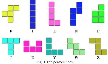
We developed an algorithm for collaborative robotics, using two 5-DOF robotic arms (all rotational) and 3-finger grippers for manipulating up to 10 pentominoes. These geometric shapes are characterized by being geometric shapes made of only 5 squares with adjacent sides, as shown in Fig. 1. Each pentomino was assigned a letter for its classification.
F I L N P
T U V W Z
Fig. 1 Ten pentominoes
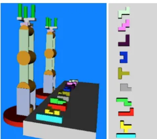
Fig. 2 Work environment and virtual pentominoes
The algorithm includes a process for detection and classification of objects in the work area, through the capture of the environment and application of an R-CNN, and also the extraction of each pentomino detected and inputting them into a DAG-CNN in charge of searching for feasible grasp points and orientation for the object being analyzed.
Fig. 3 Rotational axes of the 5-DOF plotted in the schematic representation of the manipulator.
Then, the manipulator located at the right-hand area of the table (labeled R1) grasps the figure and passes it to the second robot (labeled R2). R2 then grasps the object and locates it at the area to its left, creating a horizontal line with each of the manipulated objects, as shown later (Fig. 25).
To generate the work environment in which the object grasp and manipulation algorithm will be applied, four pentominoes were randomly placed in front of R1, each pentomino with different rotations, as shown in the left image of Fig. 4 (where the R-CNN had already been applied) and are emulated in the virtual environment, using the position and orientation data from each object as extracted by the R-CNN (right image of Fig. 4).
Fig. 4 Work environment simulation.
Each of the steps mentioned above is shown in the diagram on Fig. 5, numbered from 1 to 3, and are explained in detail in the following subsections.
Fig. 5 Algorithm operation.
B. Detection and classification of pentominoes
An R-CNN network was trained to detect and classify pentominoes in the work environment, using a database as shown in Fig. 6, where each of the pentominoes to be classified is drawn, varying their color, position, and orientation. Additionally, 64×64 pixel detection frames were used as labels for all elements, to help the network recognize the size differences of the objects.
Fig. 6 Base de Datos para la R-CNN.
R-CNN is a type of convolutional neural network that uses an image preprocessing stage of extracting the parts of the image that contain elements of interest.
Fig. 7 R-CNN flowchart.
As shown in Table 1, the architecture for the CNN used in this network was designed using small filters to extract the greatest amount of information from the image and using normalization layers to avoid distortion of the polyshape in the successive convolutions. Where CONV corresponds to a Convolution layer, RELU to the Rectified Linear Units, BATCH to a Batch Normalization, MAXPOOL to one of Maxpooling, FC to a Fully Connected, DROP to a Dropout, and SOFT to a Softmax [2].
TABLEI
CNN ARCHITECTURE
LAYERS Filter Size
HxW Stride
Number of Filters
CONV+BATCH+RELU 4x4 1 16
CONV+BATCH+RELU 4x3 1 64
MAXPOOL 2x2 2 --
CONV+BATCH+RELU 3x3 1 128
CONV+BATCH+RELU 3x3 1 256
MAXPOOL 3x3 2 --
CONV+BATCH+RELU 3x3 1 512
CONV+BATCH+RELU 3x3 1 1024
FC1+RELU+DROP -- -- --
FC2+SOFT -- -- --
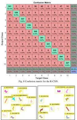
We used a MiniBatchSize of 16 images, 3536 training images and 341 test images, 10 categories and 200 training epochs. The network achieved an accuracy of 95.5% and a confusion matrix as shown in Fig. 8, where 1 is F, 2 is I, 3 is L, 4 is N, 5 is P, 6 is T, 7 is U, 8 is V, 9 is W and 10 is Z.
As seen in Fig. 8, the category with the lowest recognition rate was W, while F and U were detected with no problems. Also, 9 out of 3 pentominoes were successfully recognized in 300 test images, for which this network was selected for the application.
Fig. 9 shows two examples of polyshape detection and classification using the R-CNN, with a total of 10 pentominoes per image, where we can see that the network does not show confusion among the trained categories, only failing in cases where the polyshapes are too similar to the background, because they are not detected successfully. The value between parentheses is the confidence rate for the polyshape in the assigned category. The input image dimensions are 480×480 pixels, and the pentominoes’ dimensions are 64×64 pixels.
Fig. 8 Confusion matrix for the R-CNN.
Fig. 9 Examples of detection and classification with the R-CNN.
The value between parentheses is the confidence rate for the polyshape in the assigned category. The input image dimensions are 480×480 pixels, and the pentominoes’ dimensions are 64×64 pixels.
C. Point Detection and Grip Detection
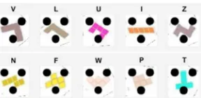
For the process of point and grip detection, each pentomino was extracted from the work environment and entered in a DAG-CNN that was trained to classify into two categories: Grasp and No Grasp, to differentiate feasible grips from not physically feasible grips, in the particular case of 3-finger grippers.
Grasp No Grasp
Fig. 10 shows an example of the database used for each category, where the black dots represent the positions of the gripper ends in the work environment. All frames were 64×64 pixels. For each image in the Grasp category, the goal was establishing stable grips based on the distance between the center of the gripper and the center of the figure, and the polyshape geometry, as is clearly shown in cases I, T, V and W of Fig. 10, where each gripper end was positioned in a way that it was able to obtain a firm grasp on the figure when closed, maintaining its geometric center very close to the center of the gripper.
As shown in Fig. 10, each pentomino was rotated and displaced in the image to search a stable grasp point,eliminating all those points where the black points overlapped the figure (category No Grasp.) This procedure was performed with the polyshapes extracted by the R-CNN in the application, as shown below.
Firstly, the information from the detection frame generated by the R-CNN was used to cut out the polyshape from the global image, and then its size was adjusted to 64×64 pixels, cutting out the long edges of the frame and padding the short edges of the frame, to avoid deforming the pentomino being re-dimensioned.
After correcting the frame dimensions, the centroid of each polyshape was extracted, and the object was displaced in a way that its centroid matched the center of the frame. Then, the three black dots representing the grippers were added to the polyshape frame, leaving it as in the examples shown in Fig. 10, and the resulting frame was inputted to the DAG-CNN for classification.
At the moment when the network classifies the image as No Grasp, the pentomino is rotated, the black dots are placed again over the rotated image, and the image is re-entered in the network. This process is repeated until the 360 degrees of rotation are tested or until the image is classified as Grasp. If no grasp is found, the polyshape is displaced one pixel up and to the right and the rotations are repeated, increasing the displacement by one for every one of the 360 degrees of rotation up to a maximum of 7 pixels, at which point the polyshape is too close to the image edge and could be cropped during rotation.
If, after all, no grasp is found, the pentomino is returned to the center of the frame and is displaced one pixel down and to the left, then is rotated incrementally up to 360 degrees, and the process is repeated until a maximum displacement of 7 pixels is achieved.
To speed up the grasp detection process, an initial rotation is performed, in which the original polyshape inclination angle (detected as shown in Fig. 17) is changed to zero degrees. This orientation was observed as having the highest probability for finding a grasp for the majority of the pentominoes, as shown in the analyses of Section III.
In case that after all the translations and rotations, no grasp point is detected, the program informs the user that no feasible grasp was found for the pentomino, and the program continues with the next pentomino. In case a feasible grasp is detected, the rotations and translations are interrupted, and the program informs that it has found a grasp for the polyshape, indicating the translation and rotation at which the grasp was found (see Table 4), and then the grasp found is plotted as shown in Fig. 11 (showing the grasp points for
the pentominoes for the left image of Fig. 9) or as shown in Fig. 12 (grasp points for the polyshapes of Fig. 4).
Fig. 11 Grasp points detected by the DAG-CNN in an example with 10 pentominoes.
Fig. 12 Grasp points detected by the DAG-CNN in an example with 4 pentominoes.
The network was trained with a total of 1800 images for category training, 50 epochs, MiniBatchSize of 18, and a DAG-CNN divided into two branches, as shown in Fig. 13, with the architecture of each branch shown in Table 2.
Fig. 13 DAG-CNN structure.
TABLEII DAG-CNN ARCHITECTURE
LAYERS BRANCH 1 Filter Size HxW
Stride Number of Filters
CONV+BATCH+RELU 4x4 1 16
CONV+BATCH+RELU 4x4 1 64
MAXPOOL 2x2 2 --
CONV+BATCH+RELU 3x3 1 128
CONV+BATCH+RELU 3x3 1 192
MAXPOOL 3x3 2 --
CONV+BATCH+RELU 3x3 1 256
CONV+BATCH+RELU 3x3 1 512
FC1+RELU+DROP -- -- --
FC2+RELU+DROP -- -- --
LAYERS BRANCH 2 Filter Size HxW
Stride Number of Filters
CONV+BATCH+RELU 4x4 1 16
CONV+BATCH+RELU 4x4 1 32
CONV+BATCH+RELU 4x4 1 64
MAXPOOL 3x3 2 --
CONV+BATCH+RELU 3x3 1 128
CONV+BATCH+RELU 3x3 1 192
CONV+BATCH+RELU 3x3 1 256
MAXPOOL 3x3 2 --
CONV+BATCH+RELU 3x3 1 512
FC1+RELU+DROP -- -- --
The network achieved an accuracy of 98.8% with a confusion matrix as shown in Fig. 14, where 1 is the Grasp category, and 2 is No Grasp.
Fig. 14 Confusion matrix for the DAG-CNN.
The confusion matrix shows how, from a total of 200 test images per category, only 4 were erroneously classified as Grasp, and 1 was erroneously classified as No Grasp. Consequently, we decided to use this network for the application.
Conversely, to know the type of information extracted by the network from each image, we plotted the activations for five different pentominoes with and without feasible grips, as shown in Fig. 15, where the intensity of the color white represents the importance of the extracted characteristic (black is completely irrelevant, and white is highly relevant). The activations for each RELU layer were extracted, preceded by a convolution, sorted from left to right, in the order shown in Table 2, where the top row shows the activations for branch 1, and the bottom row shows the activations for branch 2.
As shown, the network considered as irrelevant information both the background and black dots, and focused on extracting the complete body of the polyshape, categorizing as Grasp the objects for which the body was almost completely extracted, as in cases F, L, P, and categorized as No Grasp, the objects that presented some type of occlusion, as in cases I, N.
Fig. 15 DAG-CNN activations for F, I, L, N, P of branch 1 (top) and branch 2 (bottom).
D. Collaborative Robotics
We decided to use a workspace with only 4 pentominoes, randomly selected, as in the example shown in Fig. 4, to facilitate the visualization of the grasp point over each of them in the simulation.
Firstly, the R-CNN was executed to acquire positional information and the classification of each polyshape, with the intention of locating the virtual pentominoes on the VRML table, in front of R1.
The positions of the detection frames were converted from pixels to distances in meters, using equations 1 and 2 for X (parallel to the length of the table) and Y (parallel to the width of the table), where PpX and PpY is the distance in pixels of the detection frame, DimC is the width and height of the image in the work environment (240×240 pixels) and AjX is the equivalent in meters of the height and width of the global image (0.17×0.17m).
∗ (1)
∗
(2)
Then, the distance from the center of each polyshape and the center of R1 was measured, to determine if the object is inside or outside the working range of the robot, to discard the objects not physically accessible for R1.
Fig. 16 VRML simulation of the work environment.
Fig. 17 Polyshape inclination angle.
Then, the information obtained by the DAG-CNN was used to learn the position and orientation the gripper needed to have to grab each polyshape, where the orientation of the gripper (OrG) is equal to the negative of the rotation angle with which the DAG-CNN found the grasp for the pentomino, and the position is calculated with the equation 3 from the polyshape displacement [x y] (column and row, respectively) on which the grasp was found. Additionally, the addition of padding or edge trimming must be considered, as applied to the detection frame when adjusting it to 64×64 pixels, as explained in the previous subsection.
∗ 3232 (3)
Where RotZ is the rotation matrix respective to Z, shown in the Equation 4 where is the rotation angle where the polyshape grasp was established, the constant “32” represents half the dimension of the detection frame, and is added to locate the grasp point at the center of the frame instead of at the upper left corner (PpX, PpY), and ResY and ResX represent the adjustments made to the edges of the detection frame to adjust it to 64×64 pixels, which are obtained through Equation 5, where hpx and wpx are the height and width of the detection frame.
cos ! sin!
sin! cos ! (4)
$
ℎ &ℎ 64 2 ) * ℎ 64
2
+ (5)
For the displacement of the robots, straight-line trajectories were done, from the current position of the ripper to the next position, ensuring a displacement velocity equal to zero at the beginning and end of the trajectory, and maximum velocity at the middle. The gripper position was
measured from its degrees of freedom, so that the cinematic of the robot was handled as a 3-DOF anthropomorphic, controlling the gripper independently.
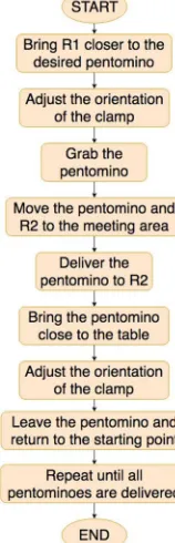
The order in which the robot movement was executed is shown in the diagram in Fig. 19, where there is a detail of which action is performed by which robot, and when the gripper orientation adjustments are performed to execute the grasp.
Fig. 18 Grasp point’s detection and classification for each pentomino, and gripper position in the work environment to perform the grasp (left to right)
For the displacement of the robots, straight-line trajectories were done, from the current position of the ripper to the next position, ensuring a displacement velocity equal to zero at the beginning and end of the trajectory, and maximum velocity at the middle. The gripper position was measured from its degrees of freedom, so that the cinematic of the robot was handled as a 3-DOF anthropomorphic, controlling the gripper independently.
The order in which the robot movement was executed is shown in the diagram in Fig. 19, where there is a detail of which action is performed by which robot, and when the gripper orientation adjustments are performed to execute the grasp.
Fig. 19 Pentominoes manipulation using two robotic arms
Fig. 20 Orientation adjustment for R1’s gripper.
Once the gripper is in position, it is lowered in a straight line until the pentomino is grasped, and then it is elevated by a few centimeters. Next, all the gripper angles are returned to their initial positions, as shown in Fig. 21.
Fig. 21 Returning all angles to their original positions.
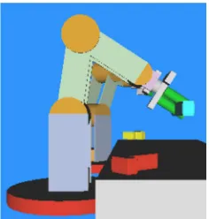
Then, the robots are moved to the rendezvous point, where the polyshape is transferred from one to the other, rotating R1’s gripper 45-degrees to avoid clashing with the fingers of R2’s gripper, as shown in Fig. 22.
Fig. 22 Transfer of the pentomino to R2.
In the next step, R2 takes the polyshape to a very close position on the table, where it adjusts the gripper angle until it is at a 90-degree angle with the table, as shown in Fig. 23. Once in that position, R2 drops the pentomino and returns the gripper angle to its original position, while R1 moves to its starting position as shown in Fig. 24.
Fig. 23 Gripper adjustment to drop the pentomino on the table.
Fig. 24 Initial position.
Finally, the process is repeated until all the polyshapes are transferred, one next to the other, at a random distance, as shown in Fig. 25, where they form a single line of pentominoes, both for 3 and 4 polyshapes.
Fig. 25 Grouped polyshapes.
III.RESULTS AND DISCUSSION
Table 3 records the time employed by the R-CNN to detect and classify all polyshapes in 5 different work environments, and the classification performed for each pentomino, and the accuracy percentage for the recognition of each element.
TABLEIII
DETECTION AND CLASSIFICATION TIMES USING R-CNN
N Work environment time(s) Classification (%)
1 6.941190
[I F W Z]
100%
2 2.663909
[L F P Z]
3 2.410071
[U W Z T]
100%
4 1.697259
[-- U P V]
75%
5 1.868316
[P N F I]
100%
PROMEDIO 3.116149 95%
As shown in Table 3, in 95% of the cases, the R-CNN can recognize all polyshapes in the work environment, with the only failures occurring when the colors of the pentomino are too similar to the background. Additionally, there was no erroneous classification for polyshape categories, and the detection and classification times are in a range of between 1.5 seconds and 7 seconds, with an average of 3.12 seconds. As the application developed does not require real-time analysis of the work environment, these times are acceptable.
Table 4 records the time taken by the algorithm to find the first feasible grasp for a polyshape, the rotation angle on which it was found, and the displacement [x y] made to the polyshape to find the grasp. At the end of the table is the calculation of the time required by the algorithm to find the grasp, without taking into consideration No Grasp cases, and the percentage of grips found compared to the total number of polyshapes evaluated.
TABLEIV
TIME USED TO DETECT GRASP POINT USING DAG-CNN
Nº Grips for each polyform time(s) Orientation (º) Position [y x]
1
F: 3.074280 Z: 1.857836 I: 1.857836 W:0.032973
F: 294º [1 -2] Z: 254º [0 3] I: -90º [-1 -1] W: 85º [-1 0]
2
P: 0.671671 L: 0.081488 Z: 1.582116 F:18.731704
P: -87º [-1 -1] L: 44º [-6 0] Z: 99º [-3 2] F: NO GRASP
3
U: 1.510001 T: 0.045901 Z: 0.033765 W:0.603594
U: 124º [-3 -3] T: -56º [3 -4]
Z: 54º [-3 2] W: 245º [-2 0]
4
V: 1.258050 U: 0.573000 P: 6.542473
--
V: 195º [-5 4] U: 164º [-4 0] P: 124º [0 6]
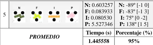
-- 5 N: 0.603257 F: 0.083933 I: 0.080530 P: 5.527346
N: -89º [-1 0] F: -83º [-1 3] I: 75º [0 -2] P: 138º [1 5]
PROMEDIO Tiempo (s) Porcentaje (%)
1.445558 95%
Table 4 shows the operation of the grasp detection process, with a 95% rate of successful grips for a total of 19 polyshapes, evaluated under a variety of positions, orientations, and colors. Also, the average time to detect grasp is 1.45 seconds, with a maximum of 7 seconds for some complex geometries such as P, and a total time of almost 19 seconds for cases with no feasible grasp detected. For other polyshapes such as W, I, N, L, T, the detection time was less than 1 second.
Additionally, in cases where the execution time was below 500ms, the grasp point was found in rotation angles between 0o and 90o. As a consequence, we can deduce that those points were detected in the first rotation generated for the polyshape, where the inclination angle of the pentomino was adjusted at or very close to 0o, achieving the proposed objective of reducing processing time with this first rotation.
IV.CONCLUSIONS
Detection of grasp points on polyshape objects using a 3-finger gripper requires a previous assessment by the programmer to determine the positions in which the grasp over each pentomino is feasible. This shows that it is possible to automate this process through the development of pattern recognition algorithms. The feasibility or not of a grasp is determined depending on how the geometry of an element fits the free space between the gripper fingers. For this reason, it is indispensable to create a database with each of the grasp positions for the polyshapes, so the network training can be focused on finding the desired grasp positions, enabling any other grasp found to be considered a feasible grasp, and eliminating the need to find additional better grasp points.
Generating an initial rotation that made the inclination angle of the polyshape of 0o compared to the horizontal, enabled to accelerate the grasp detection process for pentominoes with a geometry allowing to perform grips that are very close to that orientation, as shown in Table 4. For this reason, this initial rotation is considered to be an important factor for reducing grasp detection processing time.
The accuracy of the R-CNN trained represents a key factor in the algorithm’s operation, because an erroneous prediction or loss of information in that stage generates errors in the following steps, as is the case of not detecting a pentomino, as occurred in test number 4, on Tables 3 and 4, which prevented the DAG-CNN from finding a grasp point for the F polyshape. However, the R-CNN trained achieved a 95% accuracy in the detection and classification of polyshapes during tests, for which we conclude it has a minimal and low probability of failures.
which it is considered a feasible method for object grasping without the need of tridimensional information.
ACKNOWLEDGMENT
This research project was developed by the Davinci research groups of theMilitary University of Nueva Granada, and by the GUIAS group of the Los Libertadores University Foundation.
REFERENCES
[1] R. J. Moreno, P. C. U. Murillo, R. D. H. Beleño, Algorithm for Tool Grasp Detection, In: Colombia, International Review Of Mechanical Engineering ISSN: 1970-8734 v.12, fasc.1, p.1-8, DOI: https://doi.org/10.15866/ireme.v12i1.12513, (2018).
[2] A. Krizhevsky, I. Sutskever, G. E. Hinton, Imagenet classification with deep convolutional neural networks, In Advances in neural information processing systems, pp. 1097-1105, (2012).
[3] S. Yang, D. Ramanan, Multi-scale recognition with DAG-CNNs, In Computer Vision (ICCV), 2015 IEEE International Conference on, p. 1215-1223, (2015).
[4] C. L. Zitnick, P. Dollár, Edge boxes: Locating object proposals from edges, European Conference on Computer Vision, Springer, Cham, p. 391-405. https://doi.org/10.1007/978-3-319-10602-1_26 (2014). [5] R. Girshick, J. Donahue, T. Darrell, J. Malik, Rich feature
hierarchies for accurate object detection and semantic segmentation, In Proceedings of the IEEE conference on computer vision and pattern recognition, pp. 580-587, (2014).
[6] I. Lenz, H. lee, A. Saxena, Deep learning for detecting robotic grasps, The International Journal of Robotics Research, vol. 34, no 4-5, p. 705-724. Doi: 10.1177/0278364914549607, (2015).
[7] J. Redmon, A. Angelova, Real-time grasp detection using convolutional neural networks, En Robotics and Automation (ICRA), 2015 IEEE International Conference on, p. 1316-1322. Doi: 10.1109/ICRA.2015.7139361, (2015).
[8] S. Kumra, C. Kanan, Robotic grasp detection using deep convolutional neural networks, arXiv preprint arXiv: 1611.08036, (2016).
[9] Z. Wang, Z. Li, B. Wang, H. Liu, Robot grasp detection using multimodal deep convolutional neural networks, Advances in
Mechanical Engineering, vol. 8, no 9, p. 1687814016668077. Doi: https://doi.org/10.1177/1687814016668077, (2016).
[10] Cornell grasping dataset, http://pr.cs.cornell.edu/grasping/rect data/ data.php, accessed: 2013-09-01.
[11] N. Chen, S. Urban, C. Osendorfer, J. Bayer, P. V. D. Smagt, Estimating finger grip force from an image of the hand using convolutional neural networks and gaussian processes, In Proc. ICRA, (2014).
[12] M. Meier, F Patzelt, R. Haschke, H. J. Ritter, Tactile convolutional networks for online slip and rotation detection, In International Conference on Artificial Neural Networks, Springer, Cham, pp. 12-19, (2016).
[13] S. Levine, P. Pastor, A. Krizhevsky, J. Ibarz, D. Quillen, Learning hand-eye coordination for robotic grasping with deep learning and large-scale data collection, The International Journal of Robotics Research, vol. 37, no 4-5, p. 421-436.
Doi: 10.1177/0278364917710318, (2018).
[14] A. Jin, S. Yeung, J. Jopling, J. Krause, D. Azagury, A. Milstein, L. Fei-Fei, Tool Detection and Operative Skill Assessment in Surgical Videos Using Region-Based Convolutional Neural Networks. arXiv preprint arXiv:1802.08774, (2018).
[15] J. O. P. Arenas, R. J. Moreno, P. C. U. Murillo, Hand Gesture Recognition by Means of Region-Based Convolutional Neural Networks, Contemporary Engineering Sciences, vol. 10, no. 27, pp. 1329-1342, (2017).
[16] J. Wang, J. D. MacKenzie, R. Ramachandran, D. Z. Chen, A deep learning approach for semantic segmentation in histology tissue images, In International Conference on Medical Image Computing and Computer-Assisted Intervention, Springer, Cham, pp. 176-184, (2016).
[17] Y. F. Zheng, J. Y. S. LUH, Optimal load distribution for two industrial robots handling a single object, Journal of Dynamic Systems, Measurement, and Control, vol. 111, no 2, p. 232-237, (1989).
[18] J. Y. S. LUH, Y. F. Zheng, Constrained relations between two coordinated industrial robots for motion control, The International journal of robotics research, vol. 6, no 3, p. 60-70, (1987).