DOI: 10.9781/ijimai.2017.4410
Simple MoCap System for Home Usage
M. Magdin
Constantine the Philosopher University in Nitra, Faculty of Natural Sciences , Department of Computer Science, Tr.
A. Hlinku 1, 949 74 Nitra, Slovakia
Abstract — Nowadays many MoCap systems exist. Generating 3D facial animation of characters is currently realized by using the motion capture data (MoCap data), which is obtained by tracking the facial markers from an actor/actress. In general it is a professional solution that is sophisticated and costly. This paper presents a solution with a system that is inexpensive. We propose a new easy-to-use system for home usage, through which we are making character animation. In its implementation we paid attention to the elimination of errors from the previous solutions. In this paper the authors describe the method how motion capture characters on a treadmill and as well as an own Java application that processes the video for its further use in Cinema 4D. This paper describes the implementation of this technology of sensing in a way so that the animated character authentically imitated human movement on a treadmill.
Keywords — Multimedia, MoCap, Animations, LED Sensors.
I. I
ntroductIonc
oncEPt of real animation realized by hand drawing was created by J.Stuart Blackton. His most famous film is “Humorous Phases of Funny Faces” from the year 1906. This film has only three minutes, but it is considered the first animated film ever and Blackton as the first true animator - creator.Gradually developed technologies led to improved animations and more approach to reality. Their foundation was interactivity - an inherent feature of multimedia. Therefore, we can conclude that the use of interactive and multimedia elements has a big impact. To create the impression of reality, a method using the movement of real people, which is transmitted to an animated character, was started to be used [36].
According to [24], the Animation Society is currently discussing the definition of animation. The way in which the introduction of new techniques interferes with the creative process of traditional animation production calls into question the concept of animation. The introduction of computers brought a “new pencil”, with animation now under the influence of digital manipulation, currently recognizing the fascination with the effect of animation [37]. Today, films that are structured around visual effects, such as the Wachowski brothers’ The Matrix (Warner Bros., 1999), point towards a path where today’s film could be a sub-genre of animation [25].
According to [1], over the last three decades researchers from vision, computer graphics and robotics had been presenting methods for automatically generating camera control paths, which can be used in a large set of 3D applications. This problem is considered hard because of the large configuration space, as well as the huge number of factors that can affect the camera control [8, 27, 32, 14, 13]. The universal popularity of 3D games, which are based on human animation and 3D virtual environments, poses the camera control algorithms of an even more difficult problem, the capturing of human action scenes [1]:
1. The human character is an articulated object with many degrees of freedom. As a result, human motions are complex and its analysis is considered hard.
2. Human actions generally include several participating limbs, which have a prominent role in expressing the actual action. As a result, unlike in movement of simple geometric objects, the selection of expressive viewpoints should be affected by analyzing the motion and visibility of the body parts.
3. Small changes in the character pose often imply significant changes in the desired viewpoints for capturing this motion well. 4. The significance of the human actions is non-uniform over time.
For example, routine actions such as a walk are visually less significant than a high action karate kick.
An efficient procedure is realized by using the motion capture data (MoCap data), which is obtained by tracking the facial markers from an actor/actress. In some cases of artistic animation, the MoCap actor/ actress and the 3D character facial animation show different expressions. For example, from the original facial MoCap data of speaking, a user would like to create the character facial animation of speaking with a smirk. In this paper, we propose a new easy-to-use system for home usage, through which we are making the character animation [16].
According to [18], Motion capture (MoCap) data is extensively used in many multimedia applications such as in entertainment e.g., dance recording and training [5], in gaming e.g., cloud gaming [4], online gaming [22], etc., streaming animation [31] and online physical rehabilitation [34], [21] et al.
The first mention of using motion capture of human is from 1970, when the army used this technology for determining the position of the head of pilots when starting and landing on an aircraft carrier. A few years later the technology has started to be used for medical purposes in rehabilitation facilities. From the late 80s this technology is used in the entertainment industry. The definition of motion capture appears in 1995 in the work of Scott Dyer: “Capturing motion involves measurement of the position of the object as well as its orientation in physical space, in a way appropriate for work in computer. Objects of interest are human and other bodies, facial expressions, position cameras and lights and other elements in the scene” [8].
According to [19] MoCap gives some great opportunities to animators such as timesaving, simplifying the process of animation and others. MoCap can be applied in many other fields: sport (analyzing movements), military, robotics, game industry, medicine and others. This report is focused on using accelerometers in MoCap computer animation.
Hardware technology of Motion Capture equipments can be divided into several basic groups. In general, we can not tell which group is better or has higher quality. All have their advantages and disadvantages, and each has its ideal area for realization. According to a particular situation it is ideal to consider which version to use but in many cases it is difficult to combine two different hardware systems [7].
implement jump (or otherwise to separate from the floor). The disadvantages are a slight limitation of movement and to option uses this system only for humanoid characters. While optical sensors can be used on any creature, mechanical exoskeleton captures and transmits only human skeleton, for which it was created [9].
The main drawback of optical motion capture is the interaction of light, side light sources and reflections, which are causing loss of data [9].
In the acoustic systems, there is no overlapping of sensors, but the system also has a number of disadvantages. Space suitable for scanning is highly restricted by placing receivers. Scan rate is relatively low, as it is limited by the speed of sound. If you use medium or smaller room, the sound pulses are reflected from objects and create data noise and inaccuracies [15].
According to [19] the important parameters of MoCap systems are:
• Accuracy: the error of measuring the movements of the actor. This is a basic problem to solve.
• Animation in real-time: the possibility of computer model to follow the actor’s movements with a very short (negligible) time delay. Then the actor could experiment with different movements and make corrections.
• Freedom of movements: The freedom of actor movements (acting) gives an opportunity for rich and interesting animation.
• Frames per second: the recording speed. The greater the speed the better the system will capture fast movements like running, jumping, waving etc.
• Interruptions: recording the movement with no interruption in the process.
• Identification: the ability of the system to recognize body parts.
• External influence: the independence of the system from external influence like magnetic fields or light.
• Price: the less the better. As one can guess the goal is to make high quality MoCap system with affordable price.
• Training: training the actors to work with the system.
• Portability: the ability of the system to be moved.
• Software complexity: the complexity of the software developed for data analyzing and character animating.
Motion Capturing (MoCap) is in the last decades the standard used process by which we can record the motion and translate it into mathematically-usable signals. These signals correspond to the tracking of a number of key points in space over time. The increasing demand for rendering smooth and plausible 3D motion is fueling the development of motion capture (MoCap) systems. In this paper we will describe new approach of MoCap and its implementations. Our goal is to provide simple solution for home usage - automatically generate a 3D animation that describes in detail human actions by using static camera. Our methods extend the various existing concepts.
Related previous work is reviewed in Section II. Our advanced motion classification techniques are described in Section III. Experimental results are presented and analyzed in Section IV and V. Finally, concluding remarks, discussion, comparison of results of our and other systems and possible future extensions are summarized in Section V.
II. r
ElatEdworkFor real motion capture, abbreviated MoCap, there are a number of professional and amateur solutions. Generally speaking, professional solutions (VICON, Gypsy7, Qualisys) are used in film industry and by gaming companies. They are economically very costly, but the resulting effect is high. Amateur solutions are cost-efficient, but they are inaccurate and contain many software and hardware deficiencies [8].
MoCap systems are presently standard in computer graphics, particularly in creation of 3D or 4D animations. Since there are different types MoCap systems, in this section, we describe only those studies which closely relate to our work.
The work of [12] and [13], suggests the implementation of a camera engine within a game pipeline, for the purpose of generating better viewpoint selection, and game summarization. Their system is based on solving constraints which consider a set of viewpoint quality attributes, as well as the camera control path quality. This work extends [1] by introducing attributes which relate to the subject’s action. This addition was sufficient to significantly improve the resulting camera control path for such human animation based games. While work of [13] is focused on generating results in real-time, it lacks the ability to analyze the data and search for global solutions, method of [1] suggests this solutions. However, both solutions do not offer the possibility of creating 3D or 4D animations in real time.
A similar solution as used by us appeared already in 2008. Authors [20] use in their work various static camera positions which are then extended into a camera path by interpolation. In this solution the main problem is in camera path planning occlusions between objects. This problem is described in [2], [32] and [13]. In addition to such static scene related occlusions, here we focus on examining self occlusions of the various human limbs. This extension of standard occlusion constraint methods [13] was addressed in the context of camera control only method which suggested [1].
In last decade, various compute algorithms have been proposed (simple heuristics [30], [3], minimizing degenerated projection of polygon [17], [10]). These algorithms were categorized first time by [33]. In our work we will use some of the descriptors, which have been proved as effective.
In Slovakia, professional as well as amateur solutions are used. Examples include projects resulting from the Private School of Animation. Since 2013 this school has its own animation system based on motion capture. The system is composed of twenty cameras, which is an unique worldwide level. The system handles multiple actors, what the students can try. This school provides system for private animation to companies, but again it is a costly affair.
Between amateur solutions we can include these following five projects that were implemented in the 2004, 2005, 2006, 2010, and 2011.
In 2004, the [26] proposed a partial solution to the problem using 4 cameras that are placed perpendicular to each other and the more reflective elements located on the lower limbs. Analysis of points was resolved in the program VideoSQC however animation failed to create [26].
In 2005, [23] develops the idea of the previous solution. Their conception of the problem was much more complex. They used a system of 4 cameras and reflex by using points with light reflecting directly into the camera. Like in the previous case was used the program VideoSQC for analysis of coordinates and to the animation program BlueBot in which was animated walking part of the lower limbs [23].
Project of Krocka et al. in 2006 has not added many innovations to the topic. In general, they have improved the animation but again used the same programs as the projects before them.
The last amateur solution resolved the motion sensing of human instructor. For shoot of the actor was used semi-professional system of six cameras. Using this system in normal room created a problem of restriction of movement. With the right setup of cameras was created a limited space of movement. This limited space of movement is defined as a cube with an edge of about 2 meters. A movement exceeding this space created problems in the analysis of data and caused loss of data. The pretreatment data was realized with program Vicon IQ. As an intermediary for further data processing and for creation of basic skeleton the program MotionBuilder was used. The problem arose from differences skeletons in the various programs. The construction of bone in Motion Builder is easier than construction in Poser, by converting data were again some data lost. Therefore, it happened that the limb is moved unrealistically, or some joints achieve the impossible angles, such as hand bent at the elbow backwards. Also, sometimes occurred overlapping limbs [29].
III. d
EsIgno
fs
ystEmf
ora
nImatIona
nda
nalysIso
fm
otIonPrevious researches used data processing programs created by commercial companies. After careful evaluation of the problems we have chosen the solution of creating a custom program that will analyze and export data into the required format.
We decided to use optical technology MoCap, because this variant is the cheapest financially and in establishing its own system, it does not need complex electrical circuits or special devices. For motion capture of characters several cameras or compact cameras and a set of reflective elements mounted on the actor are needed.
A. Technical Part - Motion Capture
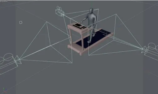
For the motion capture of a walking man we chose a scene on a treadmill. We decided to use three compact cameras, one for left and one right leg and one for front that will capture the movement of both feet. By creating separation points of different limbs when shooting from the front, we solved software analysis of coordinates. For recognizing the points we used white LEDs. This solution, however, proved to be incorrect, since the movement of the actor points often overlapped and therefore there was the loss of data similarly as in case of previous amateur solutions. For additional sensing of figures we swapped white LEDs for color ones, for ease of distinction at a later stage of analysis. We did it on the assumption that the program will use the classic RGB model. Thus, we used red, blue and green ultra-bright LEDs. Deployment of LEDs was determined intuitive. Synchronization of motion capture using cameras (3x Canon EOS 5D Mark II) has solved the light element. At some point in time, when all three cameras (Fig. 1) panned motion, we turned off/on the light in the room. This point is therefore called time zero and is a crucial element for the beginning of the analysis of coordinates.
Fig. 1. Setup of cameras.
To eliminate reflections that create ultra-bright LEDs, we used the most black (matte), light absorbing substance. The actor was dressed in black, tight-fitting clothing (Fig. 2). We have created a prerequisite for later filtering quality in the software part.
Fig. 2. The scanned Physique.
The last element that had to be solved was to eliminate non-essential elements in the captured video. This noise is in the case of optical MoCap technology everything that not is reflective elements. We therefore muted light in the room to a minimum, we filtered out other light sources which cameras catched and we left only faint, dim light necessary for orientation of the actor and the camera operator.
As can be seen in following Fig. (Fig. 3), by the movement of the feet back and forth, at the moment when this movement is the fastest, remains for the light elements a visual clue. This effect is caused by the imperfection of technique. By running the video we do not see this effect, but if we created the print screen from the video it is clear that the points are not circular cluster of pixels, but will have an ellipsoidal shape.
Fig. 3. Movement of reflex points.
Despite these imperfections, video sequences were taken approved as sufficient for our purposes. Therefore, we proceeded to the next phase, which was their modification.
B.
Software part - processing and modification of scanned
movement
when shooting from two opposite sides. As seen in Fig. 4, the left camera captures the image so that if the actor moves the left foot, the foot appears to be closer to the camera and is closer to the left edge of the image, namely is cca 260 pixels. When viewed from the right camera at the moment the actor stepped left, this limb away as 260 pixels, but from the right edge images. From the perspective of the right camera is thus rotated view mirror. When analyzing the coordinates of this, it could have caused problems with the identification of coordinates.
Fig. 4. Mirror effect.
On the video we used a scaling transformation with a matrix of horizontal rotation (1).
−
1
0
0
0
1
0
0
0
1
(1)
Analysis of the current state showed that at this stage of problem solving previous solvers had the most problems. Therefore, we decided to create a custom program that will identify and analyze the coordinates. We did not build on any existing program, we have created a program in NetBeans, build from scratch. However, we used the generated library (xuggle-xuggler), which operates with our program.Fig. 5. Correctly identified cluster.
In the program even when shooting motion figures we worked with these three colors: red (R), green (G) and blue (B). By using these colors it is clear that it is possible to use the RGB model analysis. Its use, however, also introduced even more shortcomings. We found that we do not need to know how many blue, red and
green are located around diodes. Fully sufficient was to specify only one color for each cluster. Therefore is the best using the HSV color model. This model meets our requirements almost perfectly. If we look, for example, blue color, so simply enter H than 240 ° and we are confident that we can find only blue. But even this was not a 100% solution because actually blue LEDs are off to a perfect shade of blue all the time. Pacing, we found that the color intensity of the admixture of gray was gently changing over time. Definition of the HSV model says that perfectly red color identified with H = 0 °, Green H = 120 ° and blue with H = 240 °, which represents a 120 degree interval for each basic color. So we decided to develop a tolerance for the search. Blue, therefore was procured from H = 240 °, but such an interval: H = <180 °, 300 °>, which we in the programming treated by calculating the angle = H / 360 °. This conversion no longer finds color in the interval <0,1>, which means NetBeans programming environment.
The problem is, when we identify 4 clusters (e.g. heel of the foot). This is as well as our case (shooting right and left sides).
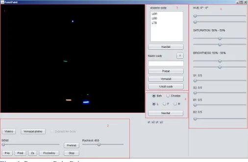
At the idea that one video has 30 frames per second and we should manually set the HSV parameters for each cluster, it would take us weeks. Also, it could happen that we would merge some clusters. This was also one of the main reasons why we have created an application JFrame PointPaint. This subroutine deals with all settings under which is realized the export of the coordinates.
PointPaint (Fig. 6) can be divided into five main components: 1. Screen.
2. Components for handling with video. 3. Sets of settings.
4. Selection of videos and view. 5. Setting of HSB values.
Each part is designed for something else and includes several components and functions, by which we can identify the coordinates as accurately as possible.
Fig. 6. Program PointPaint.
As the first step, the program determines the values x1, x2 and y1, y2
of LS_HSV. These parameters ensure that we were looking for a point in the correct area.
The second step is to define xMin, xMax, yMin and yMax. Rewriting these
Fig. 7. Identification of the specific point of the cluster.
Finally, we use a simple algorithm in which these minimums and maximums are averaged by the formulas:
2
Max Min xx
x
S
=
+
(2)
2
Max Min yy
y
S
=
+
(3)
Position of specific points represents the mean value of the individual clusters, which for us is the best solution if the cluster has a circular or ellipsoidal form.IV. m
odElIngc
haractErsInc
InEma4d
With the completion of setup of the HSV kit we achieved quite satisfactory results when identifying the clusters and specific points that cluster identified. These points were, however intended, only for each view separately, this means that each view was determined for all clusters of reflective elements, plus the corresponding grid co-ordinates. The aim of our work is but to combine several 2D coordinates into 3D coordinates for each specific reflex point. So we devised an algorithm, which converts the individual spatial coordinates.
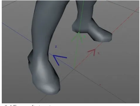
Fig. 8. Affine coordinate system.
In first step we created and defined the zero points. As seen in Fig. 8, we have created our own system of coordinates, for which the points will be recalculated. Point 0, i.e. the beginning of the coordinate
system, we have determined as the point exactly between the feet. From this point were then calculated coordinates for the export to the visualization program Cinema4D.
From this perspective it is clear that the coordinates for this coordinates system and Affine coordinate system (Fig. 8) will be completely different as are coordinates for reflex points in different views. For example, actor which standing in a room as following the Fig. (Fig. 9), has when viewed L toe of the right foot at position [405,432]. The same position also reflects previous figure. For affine coordinate system, this toe has Sx and Sy negative; Sz near around zero.
Fig. 9. Actor standing in at rest.
The outputs from the application PointPaint are the positions of all points for each image. Export was solved by generating part of the code that is inserted into an existing xml file. With the format XML we can work with program Cinema4D.
We have also programmed a number of calculations required for compatibility with the program Cinema4D. We created export of the earliest for the left leg, then for all the joints at once, and then the right foot. In first step we have to define the length of the generated code with the coordinates, representing the number of video frames, i.e. 597 (<= long in ‘597’ />).
After these adjustments, we have to export the coordinates in the form <lreal v = ‘Coordinate’ />, which is a format for coordinates in Cineme4D. We wrote the coordinates in the order of z, y, and x.
After generating all coordinates we generated the coordinates of the beginning and end of the XML file for the process to Cinema4D.
As a model we used a standard Fig. from the collection of objects for Cinemu4D. As shown in fig. 10, we chose rectangular polygonal network. Quadrilaterals well deform and have not created as sharp spike like triangles and do not require complex calculations such as polygons.
This object, however, in this state we can only edit with the moving points, which would be very laborious. By changing the coordinates of a concrete point are changing just four corresponding polygons. Model Fig. consists of 927 independent points and calculating the coordinates for each of them is unreasonable and unrealistic.
Fig. 10. Model Fig. of actor.
V. a
nImatEdm
oVEmEnto
ff
IgurEThere are several ways to create animation in Cinema4D, but the easiest and most practical is to identify the different positions of objects at different times and let the program calculate the intermediate state with using simple interpolation (keyframing).
Standard determination of positioning of individual objects unfortunately works only for simple objects. The complexity of method rigging makes it impossible to easily adjust the position of a particular joint, as this could cause breakage and separation of individual skeletal parts. Animation of movement of Fig. is therefore normally created do using only rotations.
Normally these are sufficient rotation, but for us it is important to determine the exact position of each joint and this is without giving rise to tearing or separation of the bones in the joints, what happens if we artificially specify the position of one of the joints.
Fig. 11. Rotation of joints.
Therefore, it is necessary to add to the model several effectors which represent the forces acting between the joints of humanoid figure. Thus, the humanoid Fig. will behave realistically while maintaining keyframing techniques.
These forces we have expressed their as so-called IK objects. For each leg, we added one effector between the hip and heel, what is causing that the knee is not possible to bend to an unrealistic angle, i.e. greater than 180 °. Next effectors we added between the knee and the heel.
One effector we also included between hip joints, because they represent the hip bone, which is fixed.
Several effectors have also been added to the top of the humanoid Fig. though we did not animate them. Two effectors between the arms and wrists were added for realistic movement of the upper limbs. A two effectors directly on the wrist served for the character to “caught” the handles of the treadmill. So, even if the entire model is moved slightly to either side, as it is also in normal walking, the result is that the model will hold fast to the hand and is very slightly bent at the elbows and shoulders.
The thus prepared model is suitable for direct input of coordinates for each joint. The main advantage of IK effectors is that it does not determine the absolute position of individual parts, but only determines where this part was located.
The program according to the specified coordinates attempts to approximate the spatial data and the joint moves to the position closest to the point that we have identified.
But we must not violate any of the laws of physics, when we identify the model. For example, if an error occurs in the data, which would mean that is the tip of a 80 cm distance from the heel, toe there really does not move, but try to approximate the given coordinates. The foot will then be directed to a place where we identify faulty data, but no deformation of the foot occurs.
For easy keyframing we can only set position at a certain time on a certain percentage of the curve. But that would mean that we could split the curve at the most one hundred parts, as well as specifically indicated by the percentage might not hit the individual points. The captured frames of movement had more than five hundred points, so the division into hundredths would certainly be insufficient.
Fortunately, this complex modeling can be solved using the system programming tool Xpresso. We have created a system in which we have time animation transformed to a number of animated frames. Number of frames determines the index point of the curve and the position of this point, we transferred to the object of joint pertaining to a given curve.
Fig. 12. The diagram in XPRESS.
From this moment, our character began to move in the desired manner and all joints copied movements for the data matrix.
VI. d
IscussIon-
comParIsonofourandothErm
oc
aPlEd
sEnsorssystEmsresulting effect is high. Amateur solutions are cost-efficient, but they are inaccurate and contain many software and hardware deficiencies [8].
Vicon is a professional solution of motion capture that is based on optical technology. The company supplies high-quality hardware such as cameras with the possibility of recording up to 250 frames per second. Vicon uses six various cameras for equally spaced system. The price of equipment Vicon depends from count and quality of the cameras.
taBlE I
sPEcIfIcatIonsof systEm VIcon
Specification Vicon
Camera model MX-F20
Lenses 6x4/16mm
Sensor type CMOS
Sensor dimensions 1600x1280
Price ($) 15.000-250.000
Qualisys - output is animation of a real movement. Biomechanics approach opens the possibility of analysis of movement for rehabilitation purposes, such as analysis of the lower legs during running and walking.
taBlE II
sPEcIfIcatIonsof systEm QualIsys
Specification Qualisys low-end Qualisys high-end
Camera model Miqus M1 Oqus 7+
Lenses 58x40/16mm 54x42/16mm
Sensor type CMOS CMOS
Sensor dimensions 1216x800 4096x3072
Price ($) 5.000$ 20.000$
OptiTrack offers a blend of performance and usability that produces high-precision, biomechanically-relevant motion capture data via workflows that are unprecedented in their simplicity. Motive supports numerous biomechanics marker sets, with a focus on scientific and anatomically-valid options. Whether your analysis takes place in Visual3D, The MotionMonitor, MATLAB, or another third-party tool, these marker sets provide a robust marker tracking and auto-labeller.
taBlE III
sPEcIfIcatIonsof systEm natural PoInt - oPtItrack
Specification Natural Point
Camera model Optitrack Flex V100R2
Lenses 12x4.5mm
Sensor type CMOS
Sensor dimensions 640x480
Price ($) 15.000$
Gypsy7 - this MoCap system from company Meta Motion consists of a robust structure and is fitted on the human body. The construction is durable, made of light metal in order does not obstruct the movement.
Gypsy7 is not possible to be compared with these systems because it uses a completely different method of sensing the position of an object (system price is 14.000$ to 27.000$). Qualisys offers various solutions of cameras. In the Table 2 is stated the low and high-end solution. There exist other, relatively inexpensive solutions, e.g. Microsoft Kinect - price 200$. They are not intended to create 3D animation of man walking in real time.
The basis comparison of system Vicon and NaturalPoint and determination of their accuracy did [35] in 2013. The first phase of the study investigated the static and dynamic linear accuracy of the Vicon MX and Natural Point systems. In both assessments, a standard
reference object was used (the Vicon “T” calibration object). The distance between two markers was chosen as the reference length and measured as 0.120 m using a 3 m Faro Fusion Arm (spatial accuracy = 0.104 mm). For the static test of linear accuracy, the reference object was positioned in the center of the calibrated volume. Three 10-s trials were recorded. The mean measured length of the 0.120 m object was calculated over the entire trial as the three-dimensional vector magnitude. Gait data were collected from a single participant, with an age of 22 years, height of 1.78 m and body mass of 75 kg. The linear accuracy tested identified a maximum absolute percentage error of 0.84% for the dynamic test in the mid volume of the Natural Point system. In all conditions, the Natural Point system produced higher errors than the Vicon system. No absolute percentage errors were found to exceed 1% deviation from the known length [35].
The main advantage of the PointPaint system is its accuracy. When you export the coordinates and their subsequent use, we recorded only one error in the coordinates from the five outputs (export of program). Each export contained 14328 values.
The resulting error rate is therefore only 1.39%. The advantage is also that if a system error occurs, it does not mean senseless of movement, but occurs raising the smooth movement due to physical changes kinetics model.
taBlE IV
sPEcIfIcatIonsofoursystEm PoIntPaInt
Specification Our system (PointPaint)
Camera model Canon EOS 5D mark 2
Lenses 24.0x36.0/16mm
Sensor type CMOS
Sensor dimensions 5634x3753
Price ($) 1.500$
VII.
c
onclusIonOn the basis of the analysis on current situation, we chose the use of optical technology MoCap. While we have achieved the desired objective, it was necessary to solve a number of problems associated with the formation of a complete MoCap system.
The first big problem was capturing movement of actor, and set up of the scene. It turned out that the best choice is to use multi-color LEDs while filming. It is also necessary follow-tuning videos using video filters.
The main problem was to analyze coordinates and transformation of two-dimensional views into a three-dimensional affine coordinate system. These transformations we have programmed as part of the program PointPaint. The program also served as a mediation linking technical section and section of animation. PointPaint provides import video into the Java environment and export the resulting coordinates into animation program Cinema4D.
r
EfErEncEs[1] J. Assa, D. Cohen-Or, I. Yeh, & T. Lee. Motion overview of human actions. Paper presented at the ACM SIGGRAPH Asia 2008 Papers, SIGGRAPH Asia’08
[2] W. H. Bares, S. Thainimit, S.A. McDermott. A model for constraint-based camera planning. In Smart Graphics, Papers from the 2000 AAAI Spring Symposium, AAAI Press, vol. 4, 84–91, 2000.
[3] V. Blanz, M.J. Tarr, M.J., H. H. Bulthoff. What object attributes determine canonical views. Perception 28, 5, 575–600, 1999.
[5] W. Choensawat, M. Nakamura, K. Hachimura. Genlaban: a tool for generating labanotation from motion capture data. Multimedia Tools Appl 74(23):10,823–10,846, 2014. doi:10.1007/s11042-014-2209-6 [6] M. Christie, P. OLivier. Camera control in computer graphics. In
Eurographics 2006 Star Report, 89–113, 2006.
[7] L. Dickson, Motion Capture UsesMeta Motion. 2008, on-line at http:// www.metamotion.com/motion-capture-uses/content-creation.html. [8] S. Dyer, J. Martin, J. Zulauf, Motion Capture White Paper, 12 Dec 1995,
on-line at http: //reality.sgi.com/employees/jam sb/mocap/MoCapWP_ v2.0.html.
[9] M. Furniss, “Motion capture,” MIT communications forum. 2000, on-line at: <http://web.mit.edu/comm-forum/papers/furniss.html>.
[10] F. Gómez, F. Hurtado, J.A. Sellares. Toussaint, G. T. Nice perspective projections. Journal of Visual Communication and Image Representation 12, 4, 387–400, 2001.
[11] Grafika.SK. Motion Capture už aj na Slovensku. 2014, on-line at: <http:// grafika.sk/clanok/motion-capture-uz-aj-na-slovensku/>.
[12] N. Halper, N., Helbing, R., Strothotte, T. A camera engine for computer games: Managing the trade-off between constraint satisfaction and frame coherence. In EG 2001 Proceedings, Blackwell Publishing, vol. 20(3), 174–183, 2001.
[13] N. Halper, P. Olivier. Camplan: A camera planning agent. In AAAI 2000 Spring Symposium on Smart Graphics, AAAI Press, 92–100, 2000. [14] L. W. He, M. F. Cohen, D. H. Salesin. The virtual cinematographer:
a paradigm for automatic real-time camera control and directing. In SIGGRAPH 1996 Conference Proceedings, ACM, 217–224, 1996. [15] T. Hermann, AcouMotifor Acoustic Moon Syson – An Interaactive
Sonification System for Acoustic Motion Control. 2006. E-ISBN: 978-3-540-32625-0
[16] K. Hirose, T. Higuchi. Creating facial animation of characters via MoCap data. Journal of Applied Statistics, 39(12), 2583-2597, 2012. doi:10.1080 /02664763.2012.724391.
[17] T. Kamada, S. Kawai. A simple method for computing general position in displaying three-dimensional objects. Computer Vision, Graphics, and Image Processing 41, 1, 43–56, 1988.
[18] M. A. Khan. Multiresolution coding of motion capture data for real-time multimedia applications. Multimedia Tools and Applications, , 1-16, 2016. doi:10.1007/s11042-016-3944-7
[19] N. T. Kostov, S. M. Yordanova, Y. D. Kalchev. MoCap - the advantages of accelerometers and accuracy improvement.International Journal of Mathematics and Computers in Simulation, 9, 60-64, 2015.
[20] J.-Y. Kwon, I. K. Lee. Detemination of camera parameters for character motions using motion area. The Visual Computer 24, 475–483, 2008. [21] J. S. Lin, D. Kulic. Online segmentation of human motion for automated
rehabilitation exercise analysis. IEEE Trans Neural Syst Rehabil Eng 22(1):168–180, 2014. doi:10.1109/TNSRE.2013.2259640
[22] L. Liu, A. Jones, N. Antonopoulos, Z. Ding, Y. Zhan. Performance evaluation and simulation of peerto- peer protocols for massively multiplayer online games. Multimedia Tools Appl 74(8):2763–2780, 2015. doi:10.1007/s11042-013-1662-y
[23] Ľ. Lučenič, “Animácia a vizuálna analýza chôdze človeka,” 2005, Team project FIIT STU
[24] F. Luz, Digital Animation: Repercussions of New Media on Traditional Animation Concepts. Lecture Notes in Computer Science (Including Subseries Lecture Notes in Artificial Intelligence and Lecture Notes in Bioinformatics). Vol. 6249 LNCS., 2010, doi:10.1007/978-3-642-14533-9_57.
[25] L. Manovich. Image Future. Animation 1(1), 2006, 25–44
[26] J. Mareták, “Animácia a vizuálna analýza chôdze človeka,” 2004, Team project FIIT STU
[27] H. McCabe, J. Kneafsey. A virtual cinematography system for first person shooter games. In Proceedings of International Digital Games Conference, 25–35, 2006.
[28] M. Mihalovič, “Animik – nástroj na interaktívne modelovanie animácií humanoidných postáv,” 2010, Diploma thesis.
[29] J. Nováček, “MOCAP – Snímání pohybu lidské postavy,”, 2011, Bachelor thesis.
[30] S. Palmer, E. Rosch, P. Chase. Canonical perspective and the perception of objects. Attention and Performance IX, 135–151, 1981.
[31] M. Patoli, P. Gkion, M. Newbury. White. Real time online motion capture
for entertainment applications. In: 3rd IEEE international conference on digital game and intelligent toy enhanced learning (DIGITEL), 139–145, 2010. doi:10.1109/DIGITEL.2010.39
[32] J. H. Pickering. Intelligent Camera Planning for Computer Graphics. PhD thesis, University of York, 2002.
[33] O. Polonsky, G. Patané , S. Biasotti, C. Gotsman, M. Spagnuolo, M.
What’s in an image: Towards the computation of the ”best” view of an object. The Visual Computer 21, 8-10, 840–847, 2005.
[34] M. A. Rahman. Multimedia environment toward analyzing and visualizing live kinematic data for children with hemiplegia. Multimedia Tools Appl 74(15):5463–5487, 2014. doi:10.1007/s11042-014-1864-y
[35] D. Thewlis, C. Bishop, N. Daniell, G. Paul. Next-generation low-cost motion capture systems can provide comparable spatial accuracy to high-end systems.Journal of Applied Biomechanics, 29(1), 112-117, 2013. [36] M. Vozár, P. Kuna, “Evaluation of acquired knowledge of mathematical
subjects in the field of applied informatics,” ICETA 2013 - 11th IEEE International Conference on Emerging eLearning Technologies and Applications, Proceedings, 2013, 405-410.
[37] P. Wells. The Fundamentals of Animation. AVA Publishing, 2006, Lausane