__________
* Corresponding author
E-mail addresses:[email protected](S. Badrloo);[email protected](M. Varshosaz)
DOI: 10.22059/eoge.2017.244709.1015 122
Monocular vision
based
obstacle
detection
Samira Badrloo*,Masoud Varshosaz
Faculty of Surveying andGeomatics Engineering, K.N. Toosi University of Technology, Tehran, Iran
Article history:
Received:25March2017, Received in revised form:6October2017,Accepted:3November2017
ABSTRACT
Detecting and preventing incidents with obstacles is a challenging problem. Most of the common obstacle detection techniques are currently sensor-based. Mobile robots like Small Unmanned Aerial Vehicles (UAVs) are not able to carry obstacle detection sensors such as radar; therefore, vision-based methods are considered, which can be divided into stereo and mono techniques. Mono methods are classified into two groups: Foreground-background separation, and brain-inspired methods. Brain-inspired methods are highly efficient in obstacle detection. A recent research in this field has focused on matching the Scale-Invariant Feature Transform (SIFT) points along with SIFT size-ratio factor and area-ratio of convex hulls in two consecutive frames to detect obstacles. However, this method is not able to distinguish between near and far obstacles nor the obstacles in a complex environment and, thus, is sensitive to wrong matched points. This paper aims to solve theaforementionedproblems through using the distance-ratio of matched points. Then, every point is investigated for distinguishing between far and near obstacles. The results demonstrated the high efficiency of the proposed method in complex environments. The least achieved accuracy of the algorithm was 60.0%, and the overall accuracy was 79.0%.
S
KEYWORDS
Obstacle detection
Vision-based
Mono-based
Brain-inspired
Distance-ratio
1. Introduction
Obstacle detection is an important task for many mobile robot applications like Unmanned Aerial Vehicle (UAV) navigation. Nowadays, with the increasing application of UAVs for civil purposes in photogrammetry, agriculture, first aids, lifesaving, and so on, obstacle detection is a key consideration in UAV navigation. Obstacle detection is more important when UAVs fly in lower altitudes or indoor environment with various obstacles. In these cases, using a UAV with automatic obstacle detection and prevention is crucial. Obstacle detection techniques are generally divided into two methods: Sensor-based and vision-based (Zeng et al., 2016). Sensor-based techniques require sensor data for obstacle detection. Various sensors use laser beams (Shim et al., 2006; Shang et al., 2014), radar (Ariyur et al., 2005), sonar and ultra-sound (Heidarsson et al., 2011; Menezes et
al., 2005). Sonar and ultrasonic waves have reasonable prices and are able to measure the location and direction of obstacles, but several factors, e.g. air density, can influence their results (Zeng et al., 2016). Radar waves are proper choices for that purpose in certain cases, particularly when there are not enough or suitable visual data; but radar sensors are usually large, heavy and expensive for small UAVs (Huh et al., 2015). Accordingly, the vision-based methods are recommended. These methods are either stereo or mono. Stereo techniques require obtaining the 3D model of the objects, while the mono ones do not need a 3D model. The latter techniques include background and foreground separation methods and brain-inspired methods. Background and foreground separation methods have low efficiency, and detecting obstacles by background and
321 foreground separation is not always a correct assumption
(Zeng et al., 2016). Brain-inspired methods use a similar technique based on how human understands and detects obstacles. Various studies have been performed on brain-inspired and mono-based techniques (Mori et al., 2013; Al-Kaff et al., 2017; Zeng et al., 2016). One of the key features of obstacle detection algorithms is their functionality in complex environments. As one of the recent techniques, the method proposed by Al-Kaff et al. (2017) is relatively capable of obtaining an obstacle zone in complex environments and is an important research in this field. This technique regards an obstacle as an object that is resizing in consecutive frames. At first, SIFT algorithm extracts some key points with their positions (X, Y) and sizes (S) from consecutive frames, and the matching process is performed between them. Afterwards, the points that are larger in the second frame are compared with those in previous frame. Then, the sum of size-ratio elements of SIFT in the selected points are regarded as the first criterion, and the area-ratio of the convex hulls of the points is considered to be the second criterion for obstacle detection. The conducted test in this study shows that this technique is not efficient to discriminate between the close and far obstacles, and considers farther objects as obstacles, as well. Figure 1 illustrates the separation of far from near objects in the algorithm of Al-Kaff et al. (2017). Additionally, the presence of wrong matched points will greatly affect the quality of the second criterion, i.e. the area ratio of convex hulls. Understanding the above-mentioned problems, this research aims to develop a method of Al-Kaff et al. (2017) by presenting a distance-ratio of matched points as a factor in detecting object size changes. This criterion investigates every point, so that it can discriminate between far and near points, and can be applied on complex environments. Moreover, using the average distance-ratios in matched points, this criterion is not influenced by wrong matched points.
Figure 1.The separationof far from near obstacles in the algorithmof Al-Kaff et al. (2017)
The rest of this paper is organized as follows. Section 2 provides a research background, and Section 3 explains the methodology, implementation, and evaluation. Section 4 demonstrates the conclusions.
2. Research Background
Vision-based obstacle-detection techniques include stereo-based and mono-based. Stereo-based methods are widely used for detecting obstacles (Labayrade et al., 2012;
Park et al., 2015). These methods commonly form disparity
images and 3D model of the obstacles and objects. These techniques are time-consuming; therefore, they are not suitable for real-time detection (Zeng et al., 2016). The study of Park et al. (2015) detects obstacles by obtaining disparity image and contour map.
Mono-based methods are diverse and do not need demonstrating the 3D model of objects. These techniques include background and foreground separation methods and brain-inspired methods. In background and foreground the regarded as is
obstacle separation techniques, the
foreground of the image. Mashaly et al. (2016) have introduced a technique for distinguishing sky in an image with the complex background. Their research processes the data and delivers a binary image, which separates the obstacles from the sky. Study of Huh et al. (2015) finds the horizon line for separating the sky from the ground, detects the movement of moving objects, and applies the particle-filter algorithm for detecting moving obstacles. This technique is helpful for moving obstacles, but not applicable for fixed objects. The other failing is inefficiency for indoor use and low-altitude imaging. Overall, background and foreground separation methods for object detection are limited to the images in which it is easy to separate the obstacle in background. On the other hand, the foreground is not necessarily an obstacle. This reduces the functionality of those techniques and, the assumption of obstacle-detection by separating background from foreground is not always correct (Zeng et al, 2016).
Brain-inspired techniques mimic human's obstacle comprehension techniques. For instance, Mori et al. (2013) investigate detecting and preventing the obstacles that move toward or in front of MAV camera. Their study assumes that the objects coming toward camera are subject to change in size and dimensions; hence, it uses SURF algorithm features for detecting obstacle position. Zeng et al. (2016) explain that the human eye elements are sensitive to the borders of objects, and the movement of edges or borders of the object indicate object approaching. If the right border of the object moves to the right, the left edge to the left, the bottom edge to the bottom, and the top to the top, this suggests enlargement of the object. This method is applicable only when the background is simple, but it is non-functional when the background is complex.
321 obstacles detected outside that field never harm UAV.
Additionally, since it calculates only part of the frame, calculation time is significantly reduced. In this study, some key-points are extracted with their positions (X, Y) and sizes (S) from the consecutive frames, and they are matched using Brute-Force Algorithm. Then, the matched points are selected that possess larger sizes in the second frame than those in the first one. Afterwards, the ratio of size elements of the selected points in the previous step is calculated, and the sum of ratios is obtained as the first criterion. In the next step, the ratio of convex hull area is regarded as the second factor. Eventually, if those two ratios exceed a certain threshold, all selected points will be associated with the obstacle.
One of the main features of obstacle detection algorithms is their application in complex environments; thus, the method of Al-Kaff et al. (2017) is relatively capable of illustrating obstacle zone in complex environments, while the method of Zeng et al. (2017) and other brain-inspired techniques are not efficient in such cases. Accordingly, the algorithm of Al-Kaff et al. (2017) has superiority and preference and can be applied in complex environments, but it has deficiencies in distinguish between near and far obstacles, as well. The main reason for this problem is selecting all the points that represent SIFT resize from the first to the second frame and are larger than the threshold. This causes both far and near objects to be regarded as obstacles. Besides, if wrong matched points are entered into this technique, they easily influence the convex hull and its calculated area; therefore, the second criterion
aims to develop the method of Al-Kaff et al. (2017) by presenting a suitable factor for detecting objects resize; therefore, this criterion investigates every point and extracts closer obstacles in complex environments, and discriminates between farther and closer objects. Moreover, wrong matched points should not influence the criterion.
3. Methodology
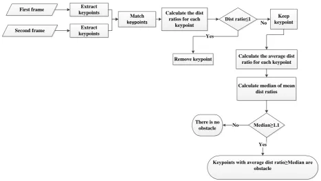
This research uses obstacle or object enlargement factor when approaching the mobile robot, and uses distance-ratio of matched points for developing a method of Al-Kaff et al. (2017) as shown in Figure 2. At first, same as the method of Al-Kaff et al. (2017), SIFT extracts and matches several points from two consecutive frames, and then, SIFT Algorithm conducts the process. Consecutive frame interval depends on the speed of the drone, scene complexity, etc., and it is one of the important parameters directly affecting the ratio of distances. Next, the distance-ratio in two consecutive frames is calculated using Eq. (1); therefore, if one has two sets of matched points, A=[1,2,3,…,n] and B=[1,2,3,...,n], in two consecutive frames, the distances between a point in the first frame and all other points in the same frame are calculated. The same procedure is conducted for the matched point of this point in the second frame as well, and the distances with all points are obtained. Afterwards, distance-ratio is calculated with Eq. (1).
Ratio(dist)=dist2(i,j)
dist1(i,j) (1)
First frame
Second frame
Extract keypoints
Extract keypoints
Match
keypoints
Calculate the dist ratios for each
keypoint
Dist ratio≤1 Keep
keypoint No
Remove keypoint Yes
Calculate the average dist ratio for each keypoint
Calculate median of mean dist ratios
Median≥1.1 There is no
obstacle No
Yes
Keypoints with average dist ratio≥Median are obstacle
321 where i, j = matched points,
dist1 (i,j) = distance between i and j in the first frame.
dist2 (i,j) = distance between i and j in the second frame.
This criterion assumes, if the object enlarges in two consecutive frames, the distance between the two matched points in these two frames grows as well; and recalculating the ratio of those two distances will definitely give a value of larger than 1. According to the criterion, in the first step, the points that are not related to an obstacle are removed. If the distance-ratio of matched points in the second frame to the first frame is less than or equal to 1, the two points of the distance are selected as the points that are probably not an obstacle. Then, the point that has the maximum selection number as non-obstacle is removed and the procedure of removing non-obstacle points is performed until no point has lower distance-ratio than 1 according to the surrounding points. Next, the remaining points will be the candidates of obstacle-related points. After removing the non-obstacle points, the remaining points were obstacle candidates, although this obstacle might be in a far or near distance. If the obstacle candidates are farther from the camera, they are subject to fewer distance changes, and conversely, the closer points indicate higher changes. The research of Al-Kaff et al. (2017) did not separate the obstacle points from each other, and all points with positive changes are detected as obstacles when the change is higher than the threshold. If the environment is complex, in order to separate the obstacle from a complex background, the current research proposes another criterion, which is able to discriminate between closer obstacles to the camera and far obstacles. In order to determine the obstacle, the average of the distance-ratios for each obstacle candidate point to other points are calculated. The average is better because it considers the
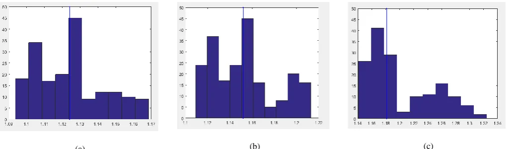
overall behavior of the point. For example, if the maximum distance ratio for a point value is used, it cannot indicate whether the obstacle is far or near; because the distance is a relative parameter and may be a point of a distant obstacle. Nonetheless, its distance ratio from the nearest obstacle point is the maximum value. Then, the threshold for averages must be determined. By plotting the histogram of averages for three consecutive frames in Figure 3, it is seen that the constant threshold value for all frames cannot be considered. Therefore, the median of all averages will be obtained. If the median is higher than the threshold, the points with a higher average than the median are regarded as obstacle-related points. This process extracts the near obstacle points and does not select the too far obstacles. If both near and far objects were considered to be obstacles simultaneously, the mobile robot would have to restrict its manoeuver in complex environments. Since near obstacles are the most dangerous objects for a mobile robot, detecting them has more priority than the far objects. In addition, using the average of matched-points distance-ratios and removing the ratios less than or equal to 1, help the selected criterion not to be influenced by wrong matched-points.
3.1 Implementation and evaluation
In this step, we used the video images obtained from a Canon camera to evaluate the method in both indoor and outdoor space. These videos include a variety of obstacles such as trees, buildings, walls, people, etc. The obtained videos were retrieved in Matlab programming environment, and their extracted frames were investigated for obstacle detection. In the next step, SIFT algorithm extracted the
matched points of the two frames.
(a) (b) (c)
Figure 3. Plotting the histogram of averages for three consecutive frames.The blue line is themedian.
The distance-ratio for SIFT algorithm was set on 0.40, to extract the match points in different exposure conditions. Next, the obstacle was obtained by calculating the average distance-ratios of each point to other points, and by determining the median for those averages; so if the median of two consecutive frames were higher than 1.1, the points with higher average than the median were regarded as
obstacle points. In order to avoid the entry of wrong decisions, the lowest amount for the distance ratio was 1.1.
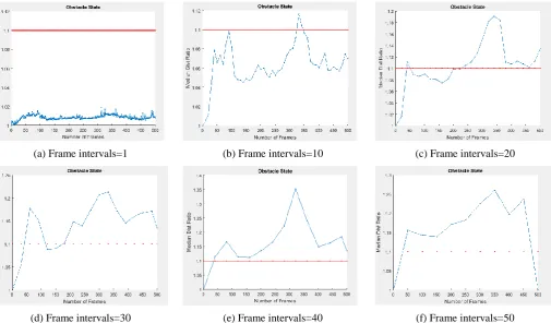
3.1.1 Selecting the optimal frame interval
321 consecutive frames, and the red line displays the threshold
value of 1.1 for the median. A blue line above the red one indicates the existence of an obstacle in that frame. However, if the consecutive frame intervals are equal to 10, the capability of obstacle identification algorithm is somewhat higher. Nevertheless, there is still a problem to identify the obstacles in frames 1 to 300. As the intervals increase from 10 to 20, the first obstacle is detected by comparing frames 20 and 40. However, there are unidentified obstacles between frames 40 and 250. If the distance between the frames is 30, then more obstacles are found in comparison with previous situation. Still, there are unidentified obstacles in frames of 100 to 200. One can identify all existing obstacles by increasing the frame intervals to 40. In frames with a distance of 50, all obstacles can be identified, as well. Nevertheless, since deletion of too many frames reduces information and data, it is optimal to select the frames with distances of 40 frames.
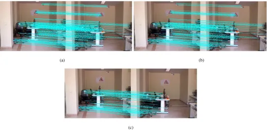
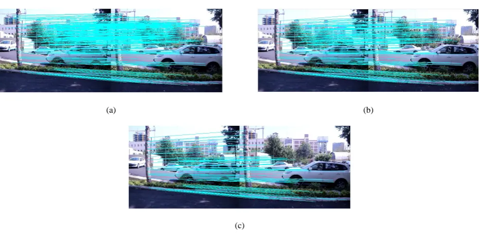
The obstacle identification algorithm was implemented by selecting the frame distance of 40, and at first, the 1st and 41st frames were examined. Totally, 108 matched points were extracted from the frames; Figure 5a shows the matched points. Later, the points with distance-ratio <= 1 were removed as non-obstacle points. Then, 67 points remained. As illustrated in Figure 5b, non-obstacle points were removed and the remaining obstacle candidate points are demonstrated. Most of the matched points that sit in the background in very far distances were eliminated in this step. If the median of two consecutive frames are higher than 1.1, the points with higher average than the median are regarded as obstacle points. In this phase, 33 points remained as obstacle points. As shown in figure 5c, the nearest objects to the camera were selected as obstacles.
(a) Frame intervals=1 (b) Frame intervals=10 (c) Frame intervals=20
(d) Frame intervals=30 (e) Frame intervals=40 (f) Frame intervals=50
321
(a) (b)
(c)
Figure 5. (a) Extracted matched points, (b) Non-obstacle points are removed and the remaining obstacle candidate points, (c) Obtained obstacle points
(a) (b)
(c)
321
(a) (b)
(c)
Figure 7. (a) Extracted 288 matched points, (b) Non-obstacle points are removed and remained 235 obstacle candidate points, (c) Obtained 117 obstacle points
(a) (b)
(c)
Figure 8. (a) Extracted 348 matched points, (b) Non-obstacle points are removed and remained 202 obstacle candidate points, (c) Obtained 100 obstacle points
As shown in Figure 7, the distant points belonging to the building were removed. On the other hand, due to the lack of extraction of SIFT points from the trees and the objects of the left side of the image, these objects were not chosen as an obstacle. In order to display the correct performance of the proposed algorithm with real sequential image data, the results of the sequential frames of one of the video are shown in Figure 9. The current algorithm was compared
321
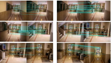
Figure 9. obstacle points extracted from sequential frames of a video
(a)
(b)
Figure 10. (a) The result of this research with obtained 20 obstaclepoints, (b) The result of Al-Kaff et al. (2017)with obtained 46 obstaclepoints
Afterwards, the convex hulls of the points were illustrated. If the sum of SIFT size-ratios of the matched points obtained by Eq. (2) are greater than 1.2, and the area-ratios of the convex hulls according to Eq. (3) are greater than 1.7, those points are selected as obstacles.
Ratio(mkp)=1
N∑
size(mkp2(i)) size(mkp1(i)) N
i=1
(2)
Ratio(c)=size(c2)
size(c1) (3)
where Size (mkp1 (i)) = The size of point i in first frame,
Size (mkp2 (i)) = The size of point i in second frame,
Size (c1) = The area of convex hull in the first frame, and
Size (c2) = The area of convex hull in the second frame. The
311
People Wall Tree obstacle Total
Number 25 30 50 80 185
Detected 20 18 43 72 153
Failed 5 12 7 8 32
Accuracy (%) 80.0 60.0 86.0 90.0 ---
Overall Accuracy (%) 79.0%
4. Conclusion
The most important function of brain-inspired object detection algorithms is their application in complex environments. As a recent technique, the technique of Al-Kaff et al. (2017) is relatively able to detect the obstacles in complex environments. However, it cannot separate far obstacles from near ones. Since detecting both far and near obstacles simultaneously restricts the space and reduces mobile robot manoeuvrability in complex environments, detecting near objects is the main priority for mobile robot navigation. Accordingly, the current research aims to develop a method of Al-Kaff et al. (2016) by proposing a suitable criterion for detecting object resize; therefore, the criterion investigates every point and extracts closer obstacles in complex environments, and is also able to separate far from near objects. Moreover, using the average of matched points distance-ratios and removing ratios <= 1, the selected criterion will not be influenced by wrong match points. The results demonstrate the high efficiency of the proposed criterion in detecting the obstacles in complex environments. In this study, the dimensions of the obstacle were not investigated. Since thin obstacles such as wire, rope and other are challenging items in searching an obstacle, they will be investigated in future research. In addition, selection of the optimal distance between the frames can be affected by speed, time, and complexity, etc., which will be investigated in future studies.
References
Al-Kaff, A., García, F., Martín, D., De La Escalera, A., & Armingol, J. M. (2017). Obstacle Detection and Avoidance System Based on Monocoular camera and Size Expansion Algorithm for UAVs. Sensors, 17(5),1-22.
Ariyur, K., Lommel, P., & Enns, D. (2005). Reactive inflight obstacle avoidance via radar feedback. in American Control Conference, Proceedings of 2005, 4, 2978–2982.
Heidarsson, H.K., & Sukhatme, G.S. (2011). Obstacle detection and avoidance of an autonomous surface vehicle using a profiling sonar. In: Proceedings of 2011 IEEE International Conference on Robotics and Automation, 731–736.
Huh, S., Sungwook, C., Yeondeuk, J., & David, S. (2015). Vision-Based Sense-and Avoid Framework for
Unmanned Aerial Vehicles. IEEE Transactions On Aerospace And Electronic Systems, 51(4), 3427-3439. Labayrade, R., Aubert, D., & Tarel, J.P. (2002). Real-time
obstacle detection in stereo vision on non-flat road geometry through “v-disparity” representation. In: Proceedings of the 2002 IEEE Intelligent Vehicles Symposium, 2, 646–651.
Mashaly, A., Yunhong, W., & Qingjie, L. (2016). Efficient sky segmentation approach for small UAV autonomous obstacles avoidance in cluttered environment. 2016 IEEE International Geoscience and Remote Sensing Symposium.
Menezes, P., Dias, J., Ara´ujo, H., & de Almeida, A. (2005). Low cost sensor based obstacle detection and description. Lecture Notes in Control and Information Sciences, 223, 231–237.
Mori, T., & Scherer, S. (2013). First results in detecting and avoiding frontal obstacles from a monocular camera for micro unmanned aerial vehicles. IEEE International Conference on Robotics and Automation (ICRA), Germany, 1750-1757.
Park, J., & Youdan, K. (2015). Collision avoidance for Quadrotor using stereo vision. IEEE Transactions on Aerospace and Electronic Systems, 51(4), 3226-3241. Shang, E., An, X., Li, J., & He, H. (2014). A novel setup
method of 3d LIDAR for negative obstacle detection in field environment. in 2014 IEEE17th International Conference on Intelligent Transportation Systems (ITSC), 1436–1441.
Shim, D., Chung, H., & Sastry, S. (2006).Conflict-free navigation in unknown urban environments. IEEE Robotics Automation Magazine, 13(3), 27–33.