© Strojniški vestnik (43) št. 1-2, str. 33-41, 1997 Tiskano v Sloveniji. Vse pravice pridržane.
© Journal o f Mechanical Engineering (43) No. 1-2, pp. 33-41. 1997 Printed in Slovenia. All rights reserved. SV: 0039-2480(97)1-R3
Prispevek k analizi sil na vodilni lopatici modelske reverzibilne
črpalke - turbine v črpalnem obratovalnem režimu
Contribution to the Analysis of Forces on the Guide-Vane
of the Pump-Turbine Model in Pumping Regime
ANDREJ PREDIN
V prispevku so obravnavane tokovne razmere v vodilniku modelske reverzibilne črpalke -turbine, analiza sil in momentov ter merilni sistem za merjenje sil in momentov na osi vodilne lopatice. Podan j e predlog m atematičnega modela nihanja vrtilnega momenta na osi vodilne lopatice in primerjava merilnih rezultatov z izračuni.
Ključne besede: turbine - črpalke reverzibilne, vodilniki turbin, razmere tokovne, sistemi merilni
In this contribution the flow conditions at the guide apparatus o f the reversible pump-turbine model, the analysis o f forces and torque at guide-vane shaft, and measurement system fo r force and torque measurement at guide-vane are treated. A new mathematical model is given fo r guide-vane shaft torque modeling, comparison o f the measurement results with theoretical calculations, and com ments on the transfer form model to original properties.
Keywords: reversible pump turbines, guide apparatus, flow conditions, measurements systems
0 UVOD
Pri sodobnem optimiranju vodilnih sistemov, predvsem vodilnih lopatic, je potrebno natančno poznavanje obrem enitev na osi vodilne lopatice. Premer osi omejuje optimalno oblikovanje oziroma izbiro ustreznega profila vodilne lopatice. Zaradi velike koncentracije obremenitev na mestu prehoda osi v lopatico mora biti os na tem mestu nekoliko tanjša od profila. Znano je, da so tanjši profili hidravlično ugodnejši od debelejših. Z raziskovanjem na modelih je m ogoče določiti obrem enitve, ki jih lahko ob upoštevanju pravil podobnega obratovanja uporabimo na izvedbah.
1 OBLIKA DELUJOČE HIDRODINAM IČNE SILE
Iz dosedanjih raziskav [1] in dostopne litera ture je znano, da je fluidni tok [2] na izstopu iz radialnega rotorja črpalk - turbin izrazito utripne in deloma tudi naključne narave. Utrip to k a je izrazit predvsem v črpalnem obratovalnem režimu, kjer je tok pojemajoč in se z večanjem premera proti izstopu iz vodilnika um irja. Utripni tok nastane zaradi relativnega vrtinca v rotorskih kanalih s končnim številom lopatic končne debeline [3]. Posledica delovanja takšnega toka [4] na vodilne lopatice je utripajoča hidro-dinamična sila in njen vrtilni moment na osi [5]. Ta obremenjuje os vodilne lopatice z utripno, deloma tudi z izmenično obremenitvijo pri pretokih, manjših od optimalnega, vendar takšna ocena še ni popolna. Obremenitve vodilne lopatice in njene osi je treba obravnavati kompleksneje, kot dinamični sistem, pri katerem so u p o šte v a n a lastn a, v s ilje n a in superponirana nihanja celotnega osnovnega vodilnega sklopa.
0 INTRODUCTION
For present-day optimisation o f the guide sys tems, especially guide vanes, knowledge o f the ex act strength loads on the guide-vane shaft is neces sary. The guide-vane shaft diam eter limits the opti mal modelling or selection o f the suitable guide-vane foil. Because o f the great load’s concentration on the place where the guide-vane shaft enters the guide-vane foil, the shaft diam eter must be thinner than the guide-vane foil at this place. It is known that the thinner guide-vane foils are hydraulically more suitable than the equal thicker guide-vane foils. By means of model research, and by considering the simi larity laws, the acting loads on the prototype may be determined.
1 PROPERTIES OF ACTING HYDRO-DYNAM IC FORCE
2 MERILNA PROGA IN TESTNI MODEL Eksperimentalne raziskave so bile izvedene v L a b o rato riju za tu rb in sk e stro je F a k u lte te za strojništvo v M ariboru na instaliranem merilnem sistemu (sl. la), ki obsega poenostavljeni model (sl. Ib) izvedene reverzibilne črpalke turbine, prirejenem za obratovanje v črpalnem režimu z zrakom kot retočnim fluidom [6], M odel ima radialni rotor onstantne širine b= 0,05 m z enajstimi lopaticami, vodilnik s štiriindvajsetimi profiliranimi in z dvanajstimi podpornim i vodilnim i lopaticam i. N a izstopu je nameščen spiralni vodilnik pravokotnega pretočnega prereza konstantne širine bs v = 0,12 m. V stopni prem er rotorja D ] = 0,36 rnT izstopni pa D2 = 0,6 m. Vstopni robovi vodilnih lopatic leže na premeru
D3 = 0,624 m.
2 EXPERIMENTAL SYSTEM AND TESTED M ODEL
The experimental research was carried out in the Laboratory for turbine machines at the Faculty o f Mechanical Engineering in M aribor where the in stalled measurement system [6] (Fig. 1 .a), which oc cupies the simplified reversible pump-turbine model (Fig. l.b), is adapted for work with air as the fluid medium. The model has a radial impeller constant width (b = 0.05), eleven impeller blades, twenty-four foiled guide-vanes, twelve foiled support v a n e s, and a spiral volute with a rectangular form, constant width ( bs = 0.12 m) on the m odel exit. The im peller intake d iam eter is D, = 0.36 m and the exit d ia meter is D2 = 0,6 m. Blade vanes intake diameter is Z)3 = 0.624 m.
a )
Sl. 1. Eksperimentalni sistem [11J a) in poenostavljeni model reverzibilne črpalke - turbine b)
3 MERILNI SISTEMI
V okviru raziskovalnega d e la je bilo razvitih več merilnih sistemov [7], Zadnji izvedeni je merilni sistem, ki temelji na načelu tehtnice sil, imenovan sistem C (sl. 2). Na dveh pomožnih oziroma merilnih oseh je na prednapetih m erilnih konzolah vpeta merilna vodilna lopatica. N a merilnih konzolah so nameščeni merilni lističi (HBM 3/350 L Y 13) povezani v tripolni Wheatstonov mostič, s čimer je dosežena te m p e ra tu rn a izra v n av a . T rije m eriln i kan ali z a g o ta v lja jo m erjen je pom ikov in kom ponent hidrodinamične sile v dveh smereh y, in y 2, v smeri pravokotno na skeletnico profila in v smeri skeletnice profila, smerx. Predpostavljena je linearna interakcija merilnih konzol med osnovnimi smermi delovanja^,
y 2 in smeri v [8], K er je profil vodilne lopatice nesim etričen v smeri y, ima merilni sistem tri lastne frekvence. Lastne frekvence sistem a so določane eksperimentalno z impulznim vzbujanjem merilnega sistema in s spektralnim analizatorjem HP 323 60C. Lastna frekvenca vodilnega sistema v smeri y t je 94 Hz, v smeri y 2 je 56 Hz in v smeri x 74 Hz (sl. 3). Iz upadajočih amplitud nihajnih zapisov lahko sklenemo, da ima merilni sistem C majhno dušenje, karje ugodno za sprem ljanje časovno odvisnih obrem enitev. Umerjanje m erilnega sistema je izvedeno vsakokrat neposredno pred merjenjem z utežmi na merilnih oseh, v vseh treh merilnih smereh.
3 M EASUREM ENT SYSTEM
An earlier m easurem ent system was devel oped in previous research work [7], The latest meas urement system, which is based on the force scale principle, is being developed. The measurement sys tem is briefly named as system C (Fig. 2). The meas urement guide-vane is fixed on two support meas urement shafts, which are fixed on the measurement cantilever beams. The m easurem ent strain gauge strips (HBM 3/350 LY 13) are placed on cantilever beams and connected to the full W heatstone bridge. In th is w ay th e te m p e ra tu re c o m p e n sa tio n is achieved. The three m easurem ent channels assure the hydrodynamic force component measurement in two directions y t and y 2 in normal direction on the guide-vane foil and in direction x in the tangential di rection on the guide-vane foil. The linear interaction [8] o f the m easurem ent cantilever beams among acting directions (y,,y2 andx) is proposed. The meas urement system C has three eigen frequencies be cause of the non symmetrical guide-vane foil in th ey direction. The eigen frequencies are determined ex perimentally by the impulse force action on the meas urement guide-vane and by spectral analyser HP 323 60C. The eigen frequency o f the m easurem ent sys tem in direction y 1 is 94 Hz, in direction y 2 is 56 Hz, and in direction x is 74 Hz (Fig. 3). From the ampli tudes o f the oscillation record the low system damp ing may be determined. This is suitable for tim e-de pendent changeable value measurements. The meas urement system is calibrated each time before the performed measurement with the weights placed on the measurement shafts in all three measuring direc tions.
•nn MERILNI LISTIČI STRAIN GAUGE STRIPS
MERILNI LISTIČI STRAIN GAUGE STRIPS
SI. 2. Merilni sistem C in osnovne merilne smeri y t , y ? in x
4 REZULTATI MERITEV 4 MEASUREMENT RESULTS
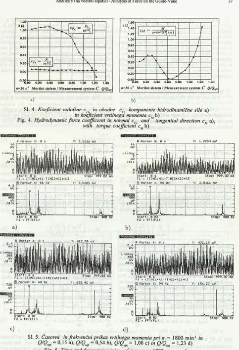
Zapis srednjih komponent hidrodinamične sile
F 'm F oziroma koeficienta sile c,, in c,, kaže na zmanjšanje obeh proti optimalnemu pretoku Q/Qopt = = 1,00 (sl. 3a). A bsolutno je kom ponenta sile v normalni smeri večja od komponente v obodni smeri, kar je tudi razumljivo, ker vodilna lopatica preusmerja tok predvsem v vzdolžni smeri. V področju pretokov
Q/Qop= 0,15 do 0,60 je komponenta sile v vzdolžni
smeri razm erom a konstantna, kar kaže na obstoj "mrtvega" cirkulacijskega toka na izstopu iz rotorja. Zapis srednjih vrtilnih momentov (sl. 4b) kaže na zvečanje vrtilnega m om enta v obm očju pretokov
Q/Qo = 0,15 do 0,80, celo večjih kakor pri obratovanju
modela z optimalnim pretokom Q/Qop=1,00 in skoraj linearno zvečevanje vrtilnega momenta v območju pretokov Q/Qopt—1,00 do 1,23.
The records o f force components Fn and F , and, force coefficients c,. and c,. have shown that both forces declined in the defection o f optimal work capacity (Q/Qopt = TOO) (Fig. 3a). The force com ponent in normal direction is absolute more than the component in the tangential direction. This is under standable because the guide-vane guides the fluid flow more in this direction than in tangential direction. In the area o f under optimal capacities ( Q/Qopt = 0.15 to 0.60) the force component in normal direction is relatively constant. This is shown by the existing "dead" circulation flow around the impeller’s exit. The mean torque record (Fig. 4b) has shown on the torque an increase in the area o f under optim al capacities
(Q/Q = 0.15 to 0.80) which are even bigger than
the torque by the optimal capacity ( ß / ß opt = 1.00) and almost linear torque increasing in the area of over optimal capacities ( Q/Qop = 1.00 to 1.23).
ft V E RAGE-- C O M P
LETE-B M a r k e r X: 2 9 3 . 9 4 5 3 1 2 m s Y: 5 0 . 1 9 3 m V B M a r k e r X: 2 9 3 . 9 4 5 3 1 2 m s Y: 5 2 . 5 6 8 m V
a) b)
7 0 m V
WrtKh&i
8. 7 5 m V
/div
0
V
2 M a r k e r X: 7 4 Hz Y: 3 1 . 0 4 4 m V
S tart: 0 Hz
S p e c t r u m C h a n 1 O V L D
Stop: 8 0 0 Hz R M S : 20
S tart: - 2 . 4 4 1 4 ms
T i m e Chan 1 O V L DStop: 4 9 7 . 0 7 ms
c )
0 .00 0 .2 0 0 .40 0.60 0 .8 0 1 .00 1.20 1.40
/1=30 s'1 M e riln i sistem / Measurem ent system C Q/Qop,
c (/)1.601.40
1.20 1.00
0.80
0.60
0.40
0.20 0.00
-0.20 -0.
---1--- 1---1--- _ M
^ e7rt/»n2(D|/zr) 1 _
\ \
0 0 0 .20 0 .4 0 0 .6 0 0 .8 0 1 .00 1 .2 0 1.40
/1=30 s‘‘ M e riln i sistem / M easurem ent system C Q/Qopt
b)
~Fn in obodne cR komponente hidrodinamične sile a) Sl. 4. Koeficient vzdolžne cf
in koeficient vrtilnega momenta cM b)
Fig. 4. Hydrodynamic force coefficient in normal cFn and tangential direction cR a),
with torque coefficient cMb)
raaaaBBBBMSiHi
fl M a r k e r X: 0 5 Y: 5 . 5 2 3 6 m V fl M a r k e r X: 9 s Y: 1 . 2 2 0 4 m V
4.S r
mV
r-6 0 0
UV
S tart: 0 s
F l = < T I M E 1 * K 1 - T I M E 2 » K 2 ) * K 3
0] M a r k e r X: 5 5 H e Y: 3 . 5 8 0 5 m V
Stop: 9 9 9 . 0 2 m s Start: 0 s
F l = ( T I M E l * i a - T I M E 2 » K 2 ) * K 3
Stop: 9 9 9 . 0 2 m s
f-..V..
-l
j-
-i
u
L...
-J
t ,J i
F 2 = F F T ( F l )
a)
R M a r K e r X:
Stop: 4 0 0 Hz
b)
-AVERAGE
-COMPLETE-0 s Y: 6 1 2 . 5 8 u V R M a r K e r X: 0 s Y: 4 3 2 . 1 9 u V
7 2 0 u V
ftaiixtmi
9 0
uV
/di v
S t a r t : 0 s
F l = ( T I M E 1 * K 1 - T I M E 2 * K 2 ) * K 3 03 M a r K e r X: 6 0 Hz
Stop: 9 9 9 . 0 2 m s
-
1
- ;
-JT
V
i
Hu
—
—
u
Start: 0 s
Fl = ( T I M E i * K i - T I M £ 2 * K 2 ) * K 3
Q3 M a r K e r X: 9 4 H z Y: 1 5 6 . 2 7 u V
S t o p : 9 9 9 . 0 2 m s
F 2 = F F T ( F l ) Stop: 4 0 0 Hz
c )
d)
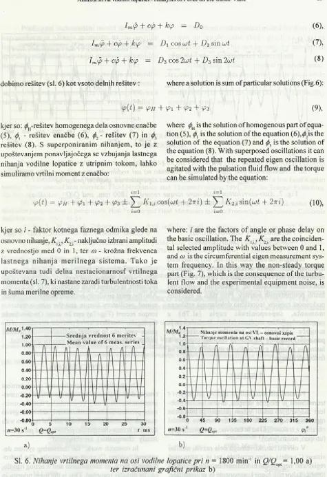
SI. 5. Časovni in frekvenčni prikaz vrtilnega momenta p ri n = 1800 min-1 in
ß / ß op, = ° ’15 a), ß / ß opt = 0,54 b), ß / ß opt = 1,00 c) in ß / ß opt = 1,23 d) Fig. 5. Time and frequency review o f torque at 1800 rpm. and
Iz časovno odvisnih zapisov vrtilnega momenta (sl. 5 - zgornji prikaz) in frekvenčne analize (sl.5 - spodnji prikaz) je razvidno, da se z zvečevanjem pretoka zmanjšujejo amplitude celotnega utripanja in amplitude lastnega nihanja (55 Hz), zvečujejo pa se amplitude vsiljenega nihanja (330 Hz). Iz tega je mogoče sklepati, da se z večanjem pretoka manjšajo amplitude utripanja vrtilnega momenta [9], veča pa se frekvenca utripanja celotnega momenta, zaradi urejanja fluidnega toka kot posledica bolj polnitve rotorskih in vodilnih kanalov.
5 PREDLOG MATEMATIČNEGA MODELA NIHANJA VRTILNEGA M OM ENTA
From the time dependent torque record (Fig. 5 - upper record) and from frequency analysis (Fig. 5 - lower record) it is evident that, with the capacity increase, the pulsation amplitudes o f eigen frequency (55 Hz) declined and at the same time the amplitude o f force frequency (330 Hz) increased. Thus it can be concluded that when the capacity increased, the pulsation torque amplitudes declined [9] and at the same time the torque frequency increased. This is a consequence o f the better impeller and guide-vane channel load.
5 PROPOSAL FOR A M ATHEM ATICAL M O DEL FOR TORQUE OSCILLATION PREDICTION Z namenom, da bi natančneje modelirali nihanje
vrtilnega momenta, je podan predlog matematičnega modela utripnih hitrosti fluidnega toka, ki temelji na linearni diferencialni enačbi petega reda:
In the research work the proposal for a math ematical model o f pulsation flow velocity has been given. The basis o f the model is the fifth order differ ential equation:
, 647T4
y(t)v +
+ &)»(<)' = 0
10 J o
s splošno obliko rešitve: with the solution in general form:
2tt 2tt 47T . 4tt
y ( t) = Cu ( t) = A 0 + A 1 c o s(— t) + B1 s i n ( - t ) + A 2 c o s(—- t) + B 2 sm ( — t)
Jo Jo Jo Jo
(1),
(2),
s konstantnimi členi, ki zajemajo geometrijske in where coefficients are constants, and model and work obratovalne parametre: parameters are:
Ao
D2
Dz 7T&2 D2 t a n / 3 2 o oQ
)
Vha 1 A i —
in and
B 1 (4),
kjer so: .0,-vstopni in Z)2-izstopni premer rotorskih lopatic, £>3-vstopni prem er vodilnika, «2 - obodna hitrost, ß 200- teoretični kot relativne hitrosti na izstopu iz rotorja, ^ -h id ra v lič n i izkoristek, a - nepopolnost rotorja in a-koeficient periodično spreminjajoče se p re to č n e p o v ršin e v o b o d n i sm eri [10]. Pri p re d la g a n e m m a te m a tič n e m m o d elu e n a č b e vsiljenega dušenega torzijskega nihanja vrtilnega momenta je enačba (2) uporabljena v brezdimenzijski obliki, kot desni - vzbujevalni del znane enačbe dušenega torzijskega nihanja:
where: D} is the intake diameter o f the front guide- vane foil boundary, w, is the circumferential velocity,
ß 200 is the angle o f relative velocity on the im p eller’s
exit, rjh is the hydraulic efficiency, a is the impeller incompleteness, and as the coefficient o f the peri odical changeable flow surface in tangential direc tion [ 10]. By the new proposal o f the forced and damp ing torsion torque mathematical model, the eq. (2) is used as the right or an excitating part o f a well-known equation:
B\ .
A2
S'},
—— sin cot -F —— cos 2cot 4- -t-
Aq Ao Aq
I m(p + op + kip — M s ( 1 + —i cos cot
^ 0 sin 2cot (5),
kjer je M srednji vrtilni moment. S postavitvijo koeficientov v nove konstante in razdružitvijo zgornje diferencialne enačbe v tri diferencialne enačbe:
Im(p + ap + k<p - D0
(6 ),Im(p +
cj>- fkip = Di
c o s u t +D2
s i n Lot (7 ),Im(p
+ap
+k<p
=D3
cos 2Lot+D3
s i n 2 ait ( 8 )dobimo rešitev (sl. 6) kot vsoto delnih rešitev : where a solution is sum o f particular solutions (Fig.6):
y {t) = <pH
kjer so: ^ -re šite v homogenega dela osnovne enačbe (5), (j)x - rešitev enačbe (6), (j>2 - rešitev (7) in rešitev (8). S superponiranim nihanjem , to je z upoštevanjem ponavljajočega se vzbujanja lastnega nihanja vodilne lopatice z utripnim tokom, lahko simuliramo vrtilni moment z enačbo:
+ P l + ¥>2 + ^3 (9), where is the solution o f homogenous part o f equa tion (5), <j)x is the solution o f the equation (6),^2is the solution o f the equation (7) and (f>3 is the solution of the equation (8). W ith superposed oscillations it can be considered that the repeated eigen oscillation is agitated with the pulsation fluid flow and the torque can be simulated by the equation:
t=i t—i
(p(t) = tpH + ipi + + V?3 ± ^ 2 K l ,ic o s ( o>t + 27r i ) ± ^ 2
K i
s in (u t + 27tz) (10),i= 0 1=0
kjer so i - faktor kotnega faznega odmika glede na where: i are the factors o f angle or phase delay on osnovno nihanje, K x., ^ .-n a k lju č n o izbrani amplitudi the basic oscillation. The K u ,K 2i are the coinciden-z vrednostjo med 0 in 1, ter ® - krožna frekvenca tal se!ected amplitude with values between 0 and 1, , . . . -, • „ , and co is the circumferential eigen measurement
sys-a stn e g sys-a n ih sys-a n isys-a m e riln e g sys-a siste m sys-a . T sys-ako ìe . e T . , . 6 J J tern frequency. In this way the non-steady torque upoštevana tudi delna nestacionarnosf vrtilnega part (Fig. 7), which is the consequence o f the turbu- momenta(sl. 7), ki nastane zaradi turbulentnosti toka lent flow and the experimental equipm ent noise, is in šuma merilne opreme. considered.
Sl. 6. Nihanje vrtilnega momenta na osi vodilne lopatice pri n = 1800 m in-1 in Q/Qop= 1,00 a)
ter izračunani grafični prikaz b)
Fig. 6. Guide-vane torque oscillations at 1800 rpm. and Q/Qopt = 1,00 a),
Sl. 7. Samokorelacijski zapis vrtilnega momenta na osi vodilne lopatice p ri n = 1800 m in'1
in Q/Q t = 1,00 a) ter izračunani superponirani grafični prikaz b)
Fig. 7. Auto-correlation guide-vane torque record at 1800 rpm. and Q/Qopt - 1,00 a),
with calculated superposed torque graphic record b)
6 PRIM ERJAVA IZRAČUNANIH MOMENTOV Z IZMERJENIMI
Iz diagramskih prikazov (sl. 6a, 6b) je razvidno ujem anje izračunanih vrednosti nihanja vrtilnega momenta na osi vodilne lopatice z eksperimentalno določenimi vrednostmi oz. s srednjimi vrednostmi šestih ponovitvenih meritev. Prav tako je razvidna podobnost zapisov teoretično določanega vrtilnega m o m e n ta , s u p e rp o n ira n i z a p is ( s l . 7b) z samokorelacijskim zapisom (sl.7a). Iz slednjega je m o g o če s k le p a ti na p ra v iln o u p o š te v a n je ponavljajočega se vzbujanja vodilne lopatice k lastnemu nihanju, s periodičnim utripnim tokom na izstopu iz rotorja.
7 SKLEPI
Po merilnih rezultatih in njihovi primerjavi s teoretičnimi je mogoče sklepati, da smo merilni prob lem zadovoljivo rešili. V tem primeru je bilo treba registrirati majhne referenčne obremenitve (model obratuje z zrakom), ki so se časovno zelo spreminjale (utripno, neustaljeno).
V okviru raziskovalnega dela razviti merilni sistem C podaja dobre rezultate, saj je z njim moč registrirati neposredno hidrodinamično silo na vodilni lopatici kakor tudi njene komponente in prijemališče, kar je bistvena prednost pred dosedanjimi merilnimi sistemi.
6 COMPARISON OF CALCULATED AND MEASURED RESULTS
The satisfactory agreement between the cal culated and measured guide-vane torque mean oscil latory values, determined from six repetition meas urements, is evident from diagrams (Fig. 6a and 6b). Also the great similarity between theoretically deter mined oscillatory torque and the auto-correlation torque record (Fig. 7a) can be seen. On this basis, the regular consideration of periodic excitation o f the guide-vane into its natural oscillation, with periodic pulsation flow at impeller exit, may be concluded.
7 CONCLUSIONS
On the basis o f experimental measurement results, the comparison between theoretical and meas urement results, it m ay be concluded that the meas uring problem has been satisfactorily solved. In given example the small referent loads (model operates with air), that is time changeable (pulsation and partly non steady changeable), are measured.
Predlagani matematični model za teoretično napovedovanje nihanja m om enta na osi vodilne lopatice daje sprejemljive rezultate, ki jih je mogoče uporabiti pri dimenzioniranju premera osi vodilne lopatice.
Glede na prenos razm er z modela na izvedbo je mogoče upoštevati samo kinematično podobnost, saj gre v konkretnem primeru za obratovanje z dvema različnima fluidoma (zrak - model, voda - izvedba).
The given mathematical model for theoretical to rq u e on g u id e -v a n e sh a ft p re d ic tio n g iv e s acceptable results. This can be used for calculation o f guide-vane shaft diam eter dimensions.
Concerning model to original parameter trans fer, only the kinematics similarity can be used, while in this case two different fluid m ediums appear. The model o p e ra tes w ith air, and th e o rig in a l facility o p e ra tes w ith water.
6 LITERATURA 6 REFERENCES
[1] Popovič, M.: Poročila raziskovalne naloge RSS od leta 1977 do leta 1992. Tehniška fakulteta, Univerza v Mariboru.
[2] Velenšek, B., K. Oberdank : Flow kinematics in a stay vane/vicked gate cascade o f a low head Kaplan turbine. Experimental heat transfear. Fluid Mechanics, and Thermodynamics 1991, Elsevier Science Publishing
Co. Inc. Amsterdam, 1991.
[3] Predin A., M. Popovič: Contribution to the experimental analysis of fluid flow in the guide wheel of the reversible pump-turbine in pump mode. Heat Transfer and Fluid Mechanics Institute Proceedings, Sacramento California State University, 1993, 41-54.
[4] R usT ., M. Jamnik: Tokovno polje v kaskadi radialne črpalke - turbine. Kuhljevi d n e v i’92, Portorož, 1992.
[5] Predin A., M. Popovič: The pivoted guide-vane oscillating in the turbocom pressor. Intern a tional Symposium on Gas Turbines and Gas Cycle Plants Proceedings. Faculty o f M echanical Engineering, University of Ljubljana, 1993, 119-130.
[6] Popovič, M.: Proučavanje pulzacionog strujanja na izlazu iz obrtnog kola reverzibilne pumpe-turbine u pumpnom radnom režimu i njegovog uticaja na oscilacije obrtnog momenta lopatice sprovodnog kola. Doktorska disertacija, Mašinski fakultet, Beograd, 1979.
[7] Predin A.-M. Popovič: Contribution to the Measurements and Analysis o f Pulsatory Hydrodynamic Forces and Torque on Guide Vanes of Pump-Turbine Systems. IMECO Technical Commitee Series; No.31 1993,137-144.
[8] Hottner T : Dreikomponenten-Windkanalwaage für interferenzffeie Messungen von Luftkraftkomponenten. Messtechnische Briefe 16, Heft 2 , 1980.
[9] Predin A.:Vpliv pulzacijskih veličin na strujne razmere v vodilniku turbočrpalnih strojev. Magistrsko delo, Tehniška fakulteta Maribor, 1990.
[10] Predin A.:Prispevek k analizi sil na vodilni lopatici modelske reverzibilne črpalke turbine v črpalnem obratovalnem režimu. Doktorska disertacija, Tehniška fakulteta Maribor, 1994.
[11] Popovič, M. : Eksperimentalno raziskovanje strujanja v modelu reverzibilne črpalne turbine. Strojniški vestnik (19) 1973/4-5.
Avtorjev naslov: dr. Andrej Predin, dipl. inž. Fakulteta za strojništvo Univerze v Mariboru Smetanova 17 2000 Maribor
Author's Address: Dr. Andrej Predin, Dipl. Ing. Faculty o f Mechanical Engineering University of Maribor
Smetanova 17
2000 Maribor, Slovenia
Prejeto:
Received: 31.1.1996
Sprejeto: