Design of loudspeaker monitoring system for nuclear power plant based on
dual MSP430
1Hong Wang, 2Bing Chen
1Research Scholar, 2Research Scholar
1, 2Electromagnetic and Information Technology Innovation Team of Electrotechnical Theory and New Technology
Laboratory, Chongqing University of Post and Telecommunications, Chonqging, China Email –1[email protected], 2[email protected]
1. INTRODUCTION:
After the Fukushima nuclear leakage accident, the safety of nuclear power plants has attracted wide attention[1]. While in the development of the national economy in China, the production of nuclear power equipment has entered a peak stage, and the design of its equipment safety and reliability becomes very important. It is necessary not only to promote the construction of nuclear power to meet China's electricity demand, but also to ensure the operational safety of nuclear power units in service, and in particular to ensure the reliability of communication terminals in the broadcasting system within the factory, so as to be able to respond to emergencies, evacuation of staff and daily work in a timely manner[3,4].
For example, cable broadcast and alarm systems are used to take charge of daily important affairs and emergency service notices in the Daya Bay Nuclear Power Plant Base. In order to ensure the normality of the broadcast system's working status, it must be regularly maintained and tested, including the cable broadcast unit damage, alarm failure and other issues [5]. Now the most advanced broadcasting system is Bosch's digital broadcasting system, which uses active terminals and can only detect the abnormalities of the transmission line. However, the abnormality of speaker sounding status can only be performed by manual inspection [6]. At the same time, due to the wide geographical area and the particularity of the nuclear power plant, the limitations of manual detection are increasingly exposed. Therefore, this article studies a kind of MSP430 single-chip based automatic monitoring and control system for loudspeakers or sirens running status. It is suitable for the high-humidity, high-noise, high-noise and high-radiation environments, and can
automatically complete the speaker or siren’s own status. Monitoring function, then upload the test results to the host (hereinafter referred to as speaker status monitoring system).
2. SYSTEM DESIGN:
The speaker condition monitoring system uses two MSP430 series microcontrollers to achieve automatic control of speaker data acquisition, analysis, and results upload and display functions. In this system, the complex tasks are divided equally between the two MCUs. The master MCU and slave MCU work together through the I2C protocol and display the speaker detection results in the host computer monitor, which in turn improves the reliability and real-time performance of the system.
In this system, the instruction to start detecting the speaker state is first issued by the I2C_TX state in the master MCU state machine. Then the slave MCU entering the idle state (IDLE), it is determined whether an instruction is received, and the corresponding state machine is started to collect the speaker sound data. It analyzes and analyzes the
Abstract: In order to monitor the health condition of the terminal unit of the broadcasting system in the nuclear power plant and ensure that the working information can be sent in time, a dual MSP430 single chip microcomputer loudspeakers monitoring system utilizing Lock-in method is designed, in which a MSP430F5529 master and a MSP430F169 slave are used respectively for system control, state memory display, data acquisition and analysis. This paper introduces the hardware circuit and software design of the speaker working condition monitoring system. I2C communication mode and software design method based on the state machine are taken advantage of to realize data exchange, command conversion and other functions between the master and slave. It is proved that the system can monitor the health condition of the loudspeaker accurately and efficiently at the host end with bit error rate less than 0.01. The system has great potential and practical value for the automatic monitoring of passive loudspeakers in the condition like nuclear power or other unattended situation with hash environment.
master MCU using MSP430F5529 microcontroller, energia with serial monitor as a development platform, the master MCU using MSP430F169 microcontroller, using Code Compser Studio (CCS) as a development platform [7].
Speaker
I2C I2C
Master MCU
MIC
PC
UART
Slave MCU
DAC ADC
Lock-in method
Fig.1 System diagram
3. HARDWARE DESIGN:
3.1 I2C interface
The serial peripheral interface I2C only requires two serial buses (clock transmission line SCL, data transmission line SDA) and supports a high-speed transmission rate of 400 kbps[8].
The I2C is configured in the master-slave mode. The SCL line is used to synchronize the clocks between the master and slaves on the SDA line. The function of the SDA line is that the master to send data or the slave send data to the master.The SDA and SCL lines are bidirectional and must use pull-up resistors to connect to the positive supply voltage. In this paper, the I2C device mode is master to receive from the slave of the peer-to-peer communication. The SDA and SCL pins of the MSP430F5529 are connected to the MSP430F169 respectively to implement master-to-slave control and data upload functions by I2C. Functional block diagram shown in Figure 2.
Fig.2 System diagram of I2C
3.2 Minimum system of MSP430F169
System storage uses Flash memory and 8MHz high-frequency crystal oscillator as the CPU main system operating clock, 32.768kHz standard crystal oscillator as the system's auxiliary clock[9,10]. Reset circuit can be MCU complex with
only need to receive more than 2us level, voltage regulator circuit with 3.3v is using for power the microcontroller. 3.3 Lock-in method
Traditional analog phase-shift lock-in methods generate a local reference signal by using a sine wave oscillator and a analog phase shift circuit[11,12]. The half-digitalphase-shift lock-in methods use a single-chip plus to do it[13].However,
Analog multiplier
Low-pass filter Bandpass filter
MCU Level translation
circuit Preamplifier
circuit Mixed
signal
Reference signal
DC signal
Fig.3 System diagram of Lock-in method
The structure is divided into an excitation unit, a weak signal acquisition unit, a front-end signal processing unit and a lock-in detection unit.The system uses an analog sound sensor as a weak signal acquisition unit, which converts the mixed sound signal of the ambient noise and the excitation signal into an analog electrical signal for subsequent processing. The front-end signal processing unit includes a pre-amplifier circuit and a narrowband filter. After the mixed signal is conditioned by the pre-amplifier circuit, a narrow band filter with the same frequency and the center frequency filters out most of the noise signals, and one related detection signal is obtained. The locke-in detection unit is the core structure of the detection method. A unipolar sinusoidal signal is directly generated by a MCU. The signal has the same frequency as the weak signal.In addition, the phase of each sine cycle is lagging behind of the previous cycle. And then it is converted into a bipolar signal using a level shift circuit which as a reference signal and sent to an analog multiplier for correlation operation.The low-pass filter can filter out the DC component of the correlation operation result and can be acquired by the ADC of the MCU[14].
4. SOFTWARE DESIGN:
4.1 Software design of master
In order to flexibly control the time of detecting the speaker without disturbing the normal broadcast activity and receive the results of detecting the speaker in real time, the host software flow mainly includes an initialization process and a state machine control process.
Program design is mainly divided into void setup () and void loop ()[15,16] in energia. Void setup() is used to initialize
the program. The program is only executed once. The initialization process mainly includes configuration of the state machine, baud rate, UART, I2C, GPIO, and system clock. Void loop () is to implement the sub-module repeat execution function, mainly to perform the state machine work.According to the system requirements, the host's state machine is divided into five working states: Case a: I2C sends a control signal to the slave;Case b: When the slave performs the detection of speaker working and data analysis, the host is waiting time 50ms in low power; case c: I2C receives the test result from the slave; case d: host serial port printing the test result to the monitor of the PC; case e: The host enters the low-power sleep state.The code flow diagram shown in Figure 4.
MSP430F5529
Start
initialize
switch:begin
case a:I2C_TX
case b:WAIT
case c:I2C_RX
case d:UART_TX case e:LOW_POWER
Send control signal
wai t
Receive the result
Upload data to PC
Enter LPM0
During initialization, the baud rate of the serial port 0 is set to 115200, the range of the DCO is 0-24 MHz, and the ACLK is equal to REFO, the MCLK and the SMCLK is 12MH, and the P4.7 port is selected as the green indicator pin[17].When designing the state machine, send a signal “S” that controls the slave to start working, and receive the
response signal “D” from the start of the slave to ensure that the master successfully controls the slave to start the detection work in case a.In case c, receiving the result in bytes. If the test result is correct, the green indicator flashes with using the serial port 0 to print the result to the monitor, and then it branches to the case d.If the detection result is error, the receiving function is executed again until the result is accurately received. In the case b, wait for 50ms until the check and analysis work.were finished in the slave. The 50ms timer is using the Comparator B comparator and timer interrupt mode of Timer A0. Comparator B generates a PWM wave with 50% duty cycle. TA0CCR1 counts once for each rising edge of PWM and stops until it reaches 50ms, then exit the interrupt. when entering interrupt mode, The main program executes other programs and the CPU enters the LMP0 mode to achieve high-efficiency and energy-saving effects.
4.2 Software design of slave
The slave software design includes three parts: initialization, state machine, and phase lock detection.
The MSP430F169 integrates a 12-bit A/D converter to convert the voltage signal into a digital value[18]. The
ADC12MCTL0 selects the standard reference voltage of 2.5V and the A1 channel is use for external input of analog signal.The ADC12CTL1 selects the rising edge of 1-MHz PWM to trigger sampling with TB.OUT1. The ADC will automatically convert the result to the corresponding ADC12MEN register after sampling. Through the rising edge of a 1-kHz PWM triggered by TB.OUT2, the DAC sends a 64-bit reference sine wave, and making the reference signal and the sampled signal operate at the same frequency with the input reference voltage of 2.5V.The DMA0 is used for DAC data transmission, and the DMA1 is for ADC data transmission, which uses byte blocks for repeated transmission.The slave address is 0x0002 in I2C, and reads and transmites data in byte format. The SDA pin is P3.1 and the SCL pin is P3.3.
The state machine is divided into five states: IDLE, I2C_RXED, UNCHECK, CHECKED, and SEND_RES.In
IDLE, enter I2C receive interrupt to determine whether the signal “S” is received or not.In the CHECKED state, setting the CheckedFlag. The slave checks the state of the flag after receiving the signal S from the host. If it is true, it indicates that the speaker has been detected, and the result can be directly returned to the host[19].If it is false, it means that the
speaker has not been detected yet. Then the UNCHECK status is used to detect the status of the speaker with using the lock-in method, and the response signal “D” is returned. At last, the speaker status data is analyzed and calculated, and set the test result flag of the ResultFlag.Among them, seting the DMA interrupt enable before starting detecting, and turning off the DMA enable immediately after the detection is completed, so as to ensure that the analysis data will not be interfered by other interrupts.In SEND_RES, it has been return the result to the host by checking the result flag. Software design flow chart shown in Figure 5.
Y
Start
initialize
switch:begin
case a:IDLE
case b:I2C_RXED
case c:UNCHECK
case d:CHECKED
case e:SEND_RES
default:
Check CheckedFlag
Send D Lock-in detection
Data analys is Set CheckedFlag
Set CheckedFlag
Check ResultFlag Upload result to host
Enter LPM0 switch:end
MSP430F169
Wether receive S or not N
Enter LPM0
Fig.5 the code flow diagram of slave
calculated.Wether the signal is correct or not by camparing the peak-to-average ratio to the threshold. For example, when it is greater than the threshold value setting the ResultFlag is TRUE, the slave returns R signal to the host, indicating that the speaker is good.On the other hand, it less than the threshold value setting the ResultFlag is FASLE, the slave echo E signal to the host, indicating the speaker is bad. When in UNCHECK, the signal D is sent back to the host that means to tell the master the slave is performing the detection work, and it must enter the waiting state to wait for the slave to send back the detection result.
5. Test Results:
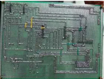
The loudspeaker is the German BOSCH-LBC3481/12 horn loudspeaker in this system, and the power of the exciter can reach 10W. The RIGOL DG1022 function signal generator provides a single-frequency sine wave which is the active excitation signal. The system shown in Figure 6 and the test results are shown in Table 1.
TABLE 1.Test results SNR/dB Speaker
status
Test results
error rate
0 normal R <0.01
-4 normal R <0.01
-8 normal R <0.01
0 error E <0.01
-4 error E <0.01
-8 error E <0.01
As can be seen from Table 1, the error rate of the speaker detection result is extremely low (<0.01), and the working status of the speaker can be automatically and effectively detected, and the detection data can be uploaded to the host.
Fig.6(c) System physical map of slave
6. CONCLUSION:
The system enables direct detection of damage to the speaker itself, rather than open circuit and short circuit conditions at the front end of the indirect detector. At the same time, a device for fully automatic detection of the speaker's health state is proposed in this paper, which overcomes the defects of the artificial judgment of speaker sound effects, and has the characteristics of high accuracy, timeliness, and safety. Therefore, the application of the system improves the reliability of the loudspeaker equipment in the nuclear power plant, and has great potential and practical value for passive loudspeakers in the field of automatic control and monitoring of nuclear power and other harsh environment without human supervision.
REFERENCES :
1. Zhang L G, Jing-Yuan Q U, Tong J J, et al. Study on Methodology for Evaluating the Capability of Nuclear Power Plants for Emergency Response. Science Technology & Engineering, 2015.
2. Bangda H U. On Transformation of U.S. Nuclear Safety Regulation Mode and Its Implications. Journal of Nanjing Tech University, 2017.
3. Gautama T, Hedebouw B. Control of a loudspeaker output: US, US 8577047 B2. 2015.
4. Chakravarty P, Zegers J, Tuytelaars T, et al. Active speaker detection with audio-visual co-training// ACM International Conference on Multimodal Interaction. ACM, 2016:312-316.
5. Guo Q, Yang D Q, Cui-Feng X U. Design Speaker Acoustic Parameters Automatic Test System. Science Technology & Engineering, 2015.
6. Mihelich R J, Hutt S W, House W N, et al. Directional loudspeaker to reduce direct sound: EP, EP1978776. 2018.
7. Min L, Chen R W, Dong J. The Low-power and Real-time Wireless Network Technology Based on MSP430. Science Technology & Engineering, 2012.
8. Guo Y, Yan Y, Gao F. Online identification system for illegal appliances based on MSP430. Application of Electronic Technique, 2017.
9. Long X, Huang M, Fan C. Weak signal detection device based on MSP430. Microcomputer & Its Applications, 2014.
10.Jung S N, Longtin A, Maler L. Weak signal amplification and detection by higher-order sensory neurons. Journal of Neurophysiology, 2016, 115(4):2158-2175.
11.Goh W, Hernitscheck C. This application note describes the implementation of I2C communication between the MSP430F16x USART or the MSP430F2xx USCI I2C hardware module and an external EEPROM (24xx128). Journal of Cleaner Production, 2015, 107:653-661
12.Qizhong Zhou,Yongle Xie,and Xuan Xie. Method for Analog Circuit Soft-Fault Diagnosis and Parameter Identification Based on Indictor of Phase Deviation and Spectral Radius. Journal of Electronic Science and Technology, 0, (): 1-10.
13.Zhang Y, Tang J, Zhao N, et al. A Design of Digital Dual-Phase Lock-in Amplifier Applied to Resonator Fiber Optic Gyro. Chinese Journal of Sensors & Actuators, 2018.
14.Li J. Design and realization on analog multiplication function of AD633. Experimental Technology & Management, 2015.
15.Sun C, Chen Y P, Zhang G, et al. Multipoint weak signal acquisition based on orthogonal vector of the lock-in amplifier// International Conference on Electronics, Electrical Engineering and Information Science. 2017. 16.Li H, Wang R, Cao S, et al. Weak signal detection using multiscale morphology in microseismic monitoring.
Journal of Applied Geophysics, 2016, 133:39-49.
17.Shen T A, Tu Y Q, Li M, et al. An improved method for phase difference measurement based on correlation theory. Journal of Vibration & Shock, 2014, 33(21):177-182.
18.Zhang G, Li H. Wavelet-EMD and stochastic resonance cascade weak signal detection. Journal of Electronic Measurement & Instrumentation, 2018.