Developing an Automatic Control System Based on the Neural Controller
Jun Su
Hubei University of Technology, Wuhan, China e-mail: [email protected]
Markiyan Nakonechnyi, Orest Ivakhiv
Lviv Polytechnic National University, 12 Bandera Street, Lviv, 79013, Ukraine
Anatoliy Sachenko
Ternopil National Economic University 3 Peremohy Square, Ternopil, 46020, Ukraine
e-mail: [email protected] Silesian University of Technology, Gliwice, 26 Roosevelta St, 41-800, Poland
http://dx.doi.org/10.5755/j01.itc.44.3.7717
Abstract. Mostly the dynamics of controlled objects is described by nonlinear equalizations. For nowadays the methodology of neural networks is engaged into designing the systems controlling nonlinear objects. These nonlinearities can be taken into account by nonlinear functions of the activation. Neural networks methodology brings some intelligence to the designed system.
We propose both the purposeful procedure of forming the structure of the neural controller according to the desired law of the control using the discrete transformation of the motion equation and proper combination an object with controller that provides the formation of a desired output signal. Requirements to the mathematical model of the reference and method of network training are determined, and the control quality is estimated both at traditional passing the disagreement error in the controller input and for the new configuration of its input circuit, namely with separated inputs, proposed in this paper. Simulation results confirmed the better quality of the system control in the last case.
Keywords: neural controller; dynamic object; neural networks; nonlinear systems.
1. Introduction
Any real dynamic object possesses some inertia characterized by a certain transient process that causes a bit delayed response of an object to the changes of the values of input signals. Furthermore, in some cases, different disturbances produce an effect on the object, which also leads to changes of the output value at the input value being constant. An appropriate mathematical model of an object is constructed based on the available information on the physical processes taking place therein. Frequently, the creation of such a mathematical model based on the known theoretical dependencies turns out to be a difficult task, and if the
characterristics of an object by applying sinusoids of different frequencies to the input, and further on, in order to build a proper controller, one can use representation of an object in the form of frequency characteristics [1]. The method of frequency characteristics uses the frequency characteristics both of the controller and the object. As well as the root hodograph method involves synthesizing a controller by placing into a defined region the roots of the characteristic equation of a system, formed by the controller and the model of an object, given in the form of a transfer function. In both cases, the requirements to the formed system are assigned indirectly, i.e., in the form of a specified zone of the location of the roots of a characteristic equation or in the form of a desired frequency characteristic of a system. Today, the linear dynamic objects appear to be quite thoroughly researched, and the methods of their control have been worked out.
Concerning the nonlinear dynamical systems, it is difficult to construct an analytical model in this case, so it is expedient to use a method that provides the capability of automatically building up the necessary models. This method is based on using artificial neural network (ANN) [2] as a universal approximating device, which in the process of training based on defined sequences, can accommodate to the input data in order to get at the output of the network the values as close as possible to the related output signals given in the form of the objective function. Nowadays the ANN methodology is implemented in the dynamic processes modeling [3-6], optimal control of chemical reactors [7], diagnostics [8, 9], drying processes and dynamics of products degradation [10, 11]. In the same time concrete procedures of the structure of the neural controller formation, the number of layers and delay lines selecting are not described (first case) or are considered as some art complemented by trial-and-error method enriched by researcher’s experience (second case). In the first case we formulated the objective towards a technique developing the conscious selection of the input circuit structure of a neural controller which should fit a desired law. The proposed technique is based on the discrete presentation of this law and determination of the required number of the delay lines. In the second case, on contrary to the traditional transmission of the error signal directly at the controller’s input, we have planned to test the effectiveness of the operation of the control system using the two-port input circuit of the controller. Namely, instead of the difference between the outputs signals of the system and input source to establish these signals separately, i.e. through the appropriate delay lines of the controller. Analysis of the differences between the output signals of the reference and controlled system confirmed the feasibility of such a procedure.
If we completed training sequences sufficiently and selected the tentative architecture of controller properly then neural network is capable to identify the
object correctly. However, the neural network is incapable to recreate ever fully a real object, which is caused not only by the imperfection of the model itself, but also by the impossibility to determine its parameters precisely. In general, the created model of the object can be used in designing the controller.
An alternative approach to the controller synthesis lies in the necessity to assign rigidly a reference to which the system should be reduced. In this case, the degree of approximating the designed system to the reference is evaluated by a mismatch between the outputs of the system and the reference, for example, using the criterion of a minimum of mean square error. It’s considered [2] the most accurate model of the object that reproduces its physical prototype based on input and output signals obtained experimentally. It is necessary therefore to synthesize the controller using appropriate input and output sequences and involving the neural networks methodology.
A goal of this work is to reduce the discrepancy between the output signals of a system and the reference by improving the architecture of the neural controller.
2. The study tasks
To reach the goal above, it is necessary to follow some important steps:
1. First of all, we need to have a real nonlinear object or create its mathematical model. So let’s assume we have a concrete nonlinear object or we created its mathematical model.
2. In accordance with the selected law of the control, we form the controller structure which is defined by delay lines.
3. We select the mathematical model of the reference based on the desirable dynamics of the controlled object which sets a duration of the transient process. There is possible overcontrol to reach necessary parameters of the control law.
4. A reference provides a creation of the proper sequence which is used for the controller training. It is necessary to have numerical sequences on both an input and output of the object. All numerical sequences are stored in the computer memory.
5. A goal of the training is to select such weighing coefficients for all neurons of the controller which provide a minimum of the possible divergence between the output signals of the object and the reference.
6. After completion of the training procedure a desired structure is prepared, and values of weighing coefficients and the duration of delays are carried in the Simulink environment.
8. Finally, the controller is joined with the object, and the duration of both the transient process and delays, and a quality of reacting on the indignation (working off) are observed as well.
Here we consider the nonlinear object as the shoulder (arm) of a robot that moves in one of the six possible directions (the so-called control channel), using the results [12, 13] of experimental researching its dynamics. It was established that robots motion can be described by a nonlinear equation of the second order, namely, having a free member of the sinusoidal character:
2
2 2 10sin ( )
d y dy
y u t dt
dt
, (1)
where y is the reaction of the controlled object to the input control signal u, i.e., in the steady state, the dependence between the input and the output variables is nonlinear:
1 10arcsin
y u. (2)
It is expedient to run training the neural controller with a selected architecture using a reference which is described by the mathematical model in a form of a linear differential equation. In order to ensure the equality between the input and the output signals in a static state, their coefficients are set to be the same. Namely:
2
2 6 9 9
rk rk
rk k
d y dy
y r
dt
dt
, (3)
where rk and yrk are the input and the output signals
of the reference at the
k
- th step.Note the reference is selected according to certain conditions:
the order of differential equation has coincide with the order of the dynamic equation for the controlled object (in this case, of the second order);
values of coefficients are chosen from the condition of convergence between the output
signal of the reference and the output signal of the object in the static state;
the value of constant coefficients at the first derivative and the free component of the equation are chosen from the condition of the desired form for the transition process.
3. Neural controller design
We apply the Artificial Intelligence to create a dynamic neural network that should serve as a controller under the proportional-integral-differential control law [1], recognized as the optimal one. The control signal contains the change in the current value of the object controlled variable and its prediction (i.e., a speed of change) and the previous state are described by the equation:
0 ( )
( ) ( ) ( )
i T
q n i
d y t
u t K K y t K y t dt
dt
, (4)where u(t) is the output signal of a controller; y(t) is the difference signal at the input of a controller (
k
y
is its discrete image at the
k
- th step); Ti is theintegration period (its value is chosen on the user’s demand); Kq , Kn and Ki are coefficients at
differential, current and integral components of the formal control signal, respectively.
In operator form, this equation will look as follows:
) ( )
( Y s
s K K s K s U i n q
. (5)
So, the neural controller transfer function can be described as follows:
s K K s K s Y s U s
W( ) ( ) ( ) q n i . (6)
Dynamic neural network operates as a discrete system with the sampling step
t
, so this law (rule) should be applied in a discrete form using the replacement of the operators
by the operatorz
, i.e.
1 1
s z t , namely:
1 11
1
q i nU z
K
z
K t
W z
K
t
z
Y z
(
)
(
)
( )
(
)
1 2 1
1
1
1
1
1
q n iK
z
K
z
K t
t
z
(
)
(
)
(
)
1 21 2 1
11 12 13 14
1
2
1
1
,
(1
)
q q q
n i n
K
K
K
K
K t
K
z
z
t
t
t
w
w z
w z
w z
z
(7)where w11
KqKntKit2
t ,w
12
Kq Knt
t 2 , w13Kq t and
w
14
1
areNote that the values of those coefficients above are determined during the training procedure and are related to the coefficients of the controller equation by following expressions: Kqw13t ,
w
122
w
13
K
n
,K
i
w
11
w
12
w
13
t
. At the k-th step the difference equation
k k
u y W z , which corresponds to the
expression (7), will look as follows:
1 14 2 13 1 12
11
k k k k
k w y w y w y w u
u . (8)
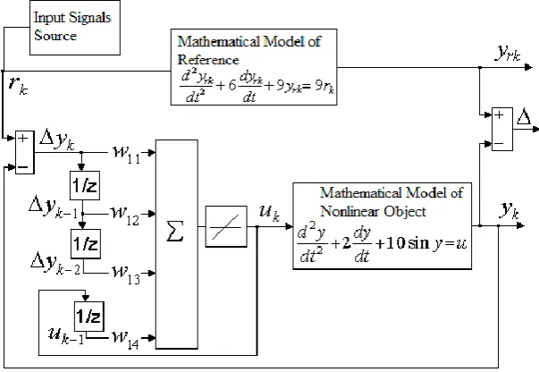
Equation (8) specifies a single-layer structure (Fig. 1) [14] of the four-input neural network with one adder and one linear circuit of activation.
Input signals to the adder are formed by four multipliers having weights 𝑤11, 𝑤12, 𝑤13 and 𝑤14,
respectively, and by three delay lines.
Figure 1. The scheme of the proportional-integral-differential discrete controller
4. Methods of Training the Neural Controllers
In the generalized structure of the automatic control system (Fig. 2), the neural controller supplements the non-linear object [15] in such a way that the output signal of the formed complex is thedesired one, i.e., should maximally correspond to an output signal of the reference (іdеаlly 𝑦𝑘= 𝑦𝑟𝑘) in
case of applying any acceptable sequence 𝑟𝑘.
Since it is necessary to know the input and output signals of a neural network in order to train it, the neural controller may be trained if we simultaneously know the reference signal at the input of the neural controller (sequence rk), the feedback signal from the
object output (sequence yk), and the output signal of
the neural controller (sequence uk, that is applied to the
object output). All three above mentioned sequences are simultaneously unknown prior to training the neural network. If one sets the input signal (sequence
k
r ), then assuming that ykyrk , based on the
mathematical model of the reference, one can determine the sequence
y
k, but then the sequenceu
kremains unknown. If we assume the sequence uk is
known and apply it to the object input, then we get the sequenceykat the object output, but the sequence rk
remains unknown.
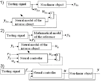
We have investigated different ways of controller training, namely using a neural model of the object, a neural inverse model of the object, and a neural inverse model of the reference.
4.1. Training the Controller Using a Neural Model of the Object
In this case (Fig. 3), a neural model of the object is formed through training the neural network and basing on sequences that are measured at the input and output of the object (uko and yko). This model is complemented
by a neural controller and it's closed by the feedback that corresponds to the real system.
A created neural network model reproduces the model combination of the controller and object. If we have a model equivalent to the reference then weight coefficients of the controller can be received by
Figure 3. Scheme of training the controller using the object neural model
а) b)
Figure 4. Dynamics of training controller using a neural model of the object (a) and a neural model of the inverse reference (b)
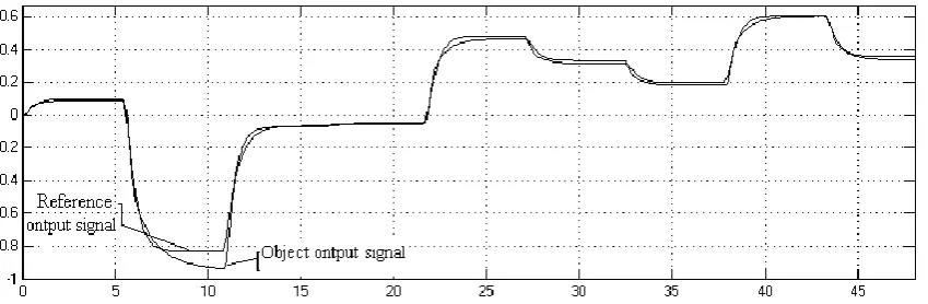
Figure 5. Comparing the output signals of a reference and an object managed by the synthesized neural controller
training of the joint network with input and output sequences of the reference (rk and yk). In this case, the
values of the coefficients, corresponding to the subnet of an object, have to be fixed, i.e., during training the coefficients of controller can change only. The
However, in this case, the neural network of the object is covered by feedback, and training of such networks usually does not provide the necessary convergence of the output signals. The dynamic analysis of training neural controller (Fig. 4,a) indicates that the duration of training (depending on the type of training se-quences) varies from 20 to 40 minutes, and its quality can be assessed by comparing the corresponding output signals (Fig. 5). Here we can see a significant distinction between signals at some controlling actions, and the larger is a deviation of the input signal from zero, the greater is the difference between the reference and output signals of the controlled object. The value of the mean error for the simulation system equals 0.023.
4.2. Training with Neural Inverse Model of the Object
With this method of training, all three sequences (rk, yk, uk) are used. The method is assigned to
deter-mine the sequence uk based on the values yk which
were obtained according to a reference sequence rk.
That is, in a normal model, a signal is passing from the input to the output, and in the inverse model, it passing in the opposite way, from the output to the input. This way requires using the object inverse model, the implementation of which is not always possible. If information about the controlled object is limited then constructing a mathematical model of the inverse object is a difficult task. Therefore, to form the input sequence of object uk based on the values of the
reference output sequence yk , one can use the neural
model of the inverse object. Training of this model is based on previously obtained experimental input uk0
and output yk0 sequences of the object (Fig. 6). Of
course, this model cannot function properly in the presence of delay and hysteresis phenomena in the object. Model creating is impossible or, at least, difficult if presented nonlinearities of the object are mixed during its inversion.
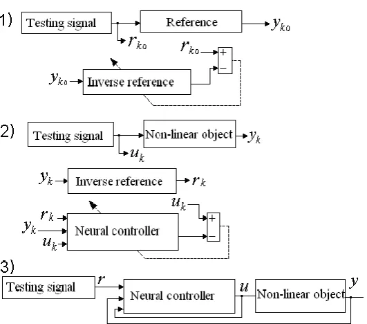
Figure 6. Scheme of the controller training with a neural model using the inverse object
For comparison purposes, the two heterogeneous controllers were constructed. For the first controller, the two-layer neural model of the inverse object was implemented including the twelve neurons with the activation functions tansig in the first layer and one neuron with the function purelin in the second layer. For the second controller, analogical models were used but with a different number of neurons in the first layer, in particular the five neurons. The simulation results confirmed that the second model of the controller provides the better convergence. The analysis of the controller training procedure using a neural model of the inverse object shows the satisfactory performance of the training process for
Figure 7. Scheme of the controller training with a neural model using the inverse reference
4.3. Training Controller using the Inverse Reference
The training is based on the sequence uk, applied to
the input object and the corresponding sequence yk,
which is taken from the object output (Fig. 7). Applying the model of the inverse reference, based on the sequence yk and taking into account the equality
yk= yrk , it is possible to get the input sequence of the
reference rk. The input sequence is transmitted to the
input of the implemented controller obtaining the control signal uk at the controller’s output. This
training scheme has a significant advantage over the previous one due to the fact that the reference is mostly simple. Therefore the procedure of construc-ting the model for the inverse reference is much simpler than for the inverse object. Reference inversion can be achieved in two ways: the first way is the solution of the reference equation towards the input variable, and the second one is the construction of the inverse model based on neural network using SIMULINK [13]. For example, let's run the reference inversion according to the equation (3) and rewrite it in the operator mode obtaining the relation
2
( ) 1
6 9
( ) 9
r r s
s s
y s . (9)
Using the substitution s
1 z1
t, we have:
21 2
2 2 2
3 1
( ) 6 2 1
( ) 9 9 9
r
t
r z t
z z
y z t t t
. (10)
For given sampling interval Δt = 0.1s, we get:
1 2
( )
18.78 28.89 11.11
( )
r r z
z z
y z
. (11)
In general, to create a model with the inverse reference it is better to use the neural network (see Fig. 7), which provides more efficient dynamics of training procedure (see Fig. 4, b).
We obtained simulation results of the automatic control system based on neural controller which was trained by using numerical sequences in the form of the different amplitude jumps(a first case) and the samples sequence of the frequency modulated sinusoid( a second case). Training for the second case was more effective than for the first one, in particular the mean square error was equal 7.0 × 10⁻³.
a)
b)
Figure 8. Comparing the output signals of the reference yr
and the system with the neural controller y (a – the
The comparison (Fig. 8, a) of output signals of the reference and the system with a neural controller trained by the ratio (8), points to a low efficiency of the system. That is, the controller, which uses signal differences
y
k for training the neural network, does not provide the required dynamic parameters of the controlled object.5. Neural Controller with Modified Input
Circuit
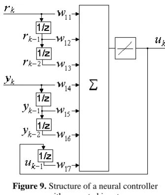
Obviously [16, 17], the difference signal created by the output signal of a system and the reference signal is applied to the input of a neural controller. In order to improve the dynamic characteristics, we use two separated inputs (ports), i.e., an output signal of a system is applied to one input (port), while the input signal of the reference is applied to other input (port). Simulation research has shown that in this case the discrepancy between the output signals of the reference and the system as well is smaller than in case of using a traditional architecture of input circuit of a neural controller. So, we proposed to feed in the controller adder separately the reference signal
r
kand its corresponding delaysr
k1,r
k2 , as well as the output signaly
kand its corresponding delaysy
k1,2
k
y
instead the error yk
rkyk
on k-th step ofthe controlling process and its previous (delayed) values yk1, yk2 in (к-1) and (к-2) steps.
The equation that describes the operation of the neural controller with two-port separated inputs (Fig. 9) looks as follows:
11 12 1 13 2
k k k k
u
w r
w r
w r
. (12) Obviously, at
w
14
w
11 ,w
15
w
12 ,13
16
w
w
this scheme(see Fig. 9) is equivalent to the scheme in Fig. 1. However during the training, the coefficients for individual inputs are set independently of each other, so it is possible to supply the control action to the object outside the circle of feedback. The value of the weight coefficientw
17 is assumed to be always fixed and equal to 1.Comparison of the output signals of the reference and the object controlled by such a controller (Fig. 8,b) shows that the system possesses better dynamic characteristics, so it confirms the feasibility of using the controller with separated inputs. In the worst case, the difference between output signals mentioned above, was equal 14,3% for the common structure of controller, and it was equal 7,1% for a controller with separate inputs. The training duration was the same for both structures and it didn't exceed 1 minute.
Figure 9. Structure of a neural controller with separated inputs
One of the perspective applications for a developed automatic control system based on the neural controller is the acquisition of multimedia data in wireless sensor networks as a segment of that system [18].
6. Conclusions
Creating the controller using the neural model of the object avoids the determination of the signal at the controller output. The structure of the input circuit of a neural controller corresponds to the selected control law. However, a training of the neural controller is characterized by the low accuracy because of feedbacks inside of the neural network. It's possible to reduce the training duration of the neural controller and improve its accuracy using a model of the inverse object or the inverse reference. The neural network with weighing coefficients, which were found during the training, supplements an object to provide a minimum of the possible difference between the output signals of an object and a reference.
Analysis of the simulation results shows that the system using the controller with separated inputs possesses better dynamic characteristics than the system with the traditional structure of controller’s input circuit, i.e., its response is closer to the one defined by the reference.
7. Acknowledgments
This work is supported by China International Science and Technology Cooperation Project (CU01-11) / State Agency on Science, Innovation and Informatization of Ukraine, Ukrainian-Chinese project No. М/23/2013 as well as Natural Science Foundation of Hubei Province of China (2014CFB605), Foundation of Wuhan Science and technology Bureau (2015030809020370).
1 17 2 16 1 15
14
References
[1] F. C. Goodwin, S. F. Fraebe, M. E. Salgado. Control System Design. Prentice Hall, Upper Saddle River, New Jercey, 2001.
[2] S. Haykin. Neural Networks – A comprehensive foundation. Pearson Education, 2001.
[3] V. G. Krishnapura, A. Jutan. ARMA Neuron Net-works for Modeling Nonlinear Dynamical Systems. Canadian Journal of Chemical Engineering, 1997, Vol. 75, No. 3, 574-582.
[4] T. W. Karjala, D. B. Himmelblau. Data Rectification for Dynamic Processes Using Artificial Neural Network. In: A.B.Bulsari (ed.). Computer Aided Chemical Engineearing. Vol. 6: Neural Networks for Chemical Engineers, Elsevier, Amsterdam, 1995, pp. 211-230.
[5] K. S. Narenda, K. Parthasarathy. Identification and Control of Dynamical Systems Using Neural Networks. IEEE Transactions on Neural Networks, 1990, Vol. 1, No. 1, 4-27.
[6] Z. Lubosny. Indentification of Dynamic Object by Neural Network. In: P.S. Szczepaniak (ed.). Computational. Intellidence and Applications, Physica-Verlag, Heidelberg – New York, 1999, pp. 228-233.
[7] N. Bhat, T. J. McAvoy. Use of Neural Nets for Dynamic Modeling and Control of Chemical Process Systems. Computers and Chemical Engineering, 1990, 14, Issue 4/5, 573-582.
[8] D. H. Wolpert, Kagan Tumer. An introduction to collective intelligence. NASA Ames Research Center, 2000.
[9] J. C. Hoskins, D. M. Himmelblau. Artificial Neural Network Models of Knowledge Representation in Chemical Engineering. Computers and Chemical
Engineering, 1988, Vol. 12, Issue 9/10, 881-890. [10] G. Jinescu, V. Lavric. The Artificial Neural Networks
and the Drying Process Modeling. Drying Technology, 1995, Vol. 13, No. 5-7, 1579-1586.
[11] W. Kaminski, P. Strumillo. Kernel Orthonormaliza-tion in Radial Basis FuncOrthonormaliza-tion Neural Networks. IEEE Transactions on Neural Networks, 1997, Vol. 8, No. 5, 1177-1183.
[12] K. S. Fu, R. C. Gonzalez, C. S. G. Lee. Robotics: Control, Sensing, Vision and Intelligence. McGraw-Hill Education (India) Pvt Limited, 1988.
[13] Neural Network Toolbox Documentation, [Online] The MathWorks Inc., Available: http://www.mathworks.com/help/nnet/index.html. [14] O. Ivakhiv, M. Nakonechnyi, T. Repetylo. System of
Neural Control by Robot Using Adaptive Methods of Training. Journal of Methods and Instrumentation for Quality Control, 2013, Vol. 1, Issue 30, 64-71. (in Ukrainian).
[15] J. B. Dabney, T. L. Harmen Mastering Simulink. Prentice Hall, Upper Saddle River, New Jercey, 2001. [16] S. M. Sharun, M. Y. Mashor, W. N. H. Wan Jaafar,
N. Mohd Nazid, S. Yaacob. Adaptive Neuro-Controller Based on Hybrid Multi Layered Perceptron Network for Dynamic Systems. International Journal of Control Science and Engineering, 2012, Vol. 2, No. 3, 34-41.
[17] H. Al-Duwaish, S. Z. Rizvi. Design of a Neuro-Controller for Multivariable Nonlinear Time-Varying Systems. WSEAS Transactions on Systems and Control, 2010, Vol. 5, No. 9, 711-720.
[18] J. Su. Method of Encoding and Transmitting the Multimedia Data in Wireless Sensor Networks. Journal of Measuring and Computing Devices in Technological Processes, 2010, 2, 203-206. (in Russian).