Volume 01, No.4, April 2015
P
age
1
Thermodynamic and Hydrodynamic Performance of Double Pipe
Heat Exchanger through Bended Strips
Mr. Amol Chaudhari* & Prof. Priyanka Jhavar*
*
ME Student, Department of Mechanical Engineering, SRI Satya Sai Institute of Science and Technology M.P., India
Professor, Department of Mechanical Engineering, SRI Satya Sai Institute of Science and Technology M.P., India
ABSTRACT:
A variety of methods for achieving improved heat transfer are usually referred to as “heat transfer augmentation” or “heat transfer enhancement” and the heat exchanger provided by means of heat transfer enhancement techniques as “Augmented Heat Exchanger”. The objective is to reduce as many of the factors as possible: Capital Cost, Power Cost, Maintenance Cost, Space and Weight, Consistent by means of safety and reliability. Present work describes the principal techniques of industrial importance for the augmentation of single phase heat transfer on the inside of tubes namely “Bended strip’’. So Bended strips should be used in heat exchanger when high heat transfer rate is required and pressure drop is of no significance. This study investigates the heat transfer characteristics of a horizontal tube-in-tube heat exchanger for single phase heat transfer by means of water as the working fluid. The material used for the construction of heat exchanger is copper, owing to its high thermal conductivity. Bended strips of varying pitches ranging from 10mm, 15mm, 20mm and 25mm respectively inserted in the inner tube. Experiments were carried out for plain tube by means of by means of out Bended strip insert at constant wall heat flux and different mass flow rates. The Reynolds number varied from 500 to 6000. Both heat transfer coefficient and pressure drop are calculated and the results are compared by means of those of plain tube.
INTRODUCTION
Volume 01, No.4, April 2015
P
age
2
by means of and by means of out pin fins under the cylindrical coordinate system. Pong jet Promvonge et.al [5] experimentally investigated the turbulent convective heat transfer characteristics in a helical-ribbed tube fitted by means of twin twisted tapes. The work has been conducted in the turbulent flow regime, Re from 6000 to 60,000 using water as the test fluid The experiment was carried out in a double tube heat exchanger using the helical-ribbed tube having a single rib-height to tube-diameter ratio, e/DH= 0.06 and rib-pitch to diameter ratio, P/DH= 0.27 as the tested section. Chii-Dong Ho [6] presents the work on efficiency improvement in heat transfer through double-pass concentric circular tubes by means of an impermeable sheet of negligible thermal resistance to divide a circular tube into two sub channels by means of uniform wall temperature and external refluxes at the ends. The introduction of reflux has position effects on the heat transfer for large Graetz number and the outlet temperature as well as transfer coefficient increases by means of increasing reflux ratio. Z. Iqbal [7] presents the optimal configurations of finned annulus by means of parabolic fins have been investigated for maximum convection by employing trust-region and genetic algorithms. Prabhata K. Swamee [8] presents the optimal design of the exchanger has been formulated as a geometric programming by means of a single degree of difficulty. M. A. Akhavan Behabadi et.al [9] presents the experimental investigation has been carried out to study the enhancement in heat transfer coefficient by coiled wire inserts during heating of engine oil inside a horizontal tube in a laminar flow heat exchanger. In present experimentation two different coiled wire insert of 2.0 mm and 3.5 mm wire thickness are used and results are carried out. The test-section was a double pipe counter-flow heat exchanger. The engine oil flowed inside the internal copper tube; while saturated steam, used for heating the oil, flowed in the annulus. The effects of Reynolds number and coiled wire geometry on the heat transfer augmentation and fanning friction factor were studied. In present work, the bended strips are used in the inner pipe having a hot water region. Therefore the design and manufacture the bended strip and study of heat transfer through them have been a problem of great interest for designer of different disciplines. The proposed study is concerned by means of experimental investigation of convective heat transfer from tube in tube heat exchanger by means of and by means of out various bended strips.
The effect of various geometries on performance characteristics of double pipe heat exchanger such as heat transfer, friction factor and pressure drop
OBJECTIVES:
i. Experimentally investigated the double pipe heat exchanger by means of bended strips having angles 15, 30, 45 and 60° by means of the central axis of the inner tube.
ii. To study thermodynamic and hydrodynamic performance of the double pipe heat exchanger.
EXPERIMENTAL SET-UP
Volume 01, No.4, April 2015
P
age
3
3.1 Experimental Apparatus
Figure 1 illustrates the experimental set-up used in the present study. The test section is a tube in tube heat exchanger. An experimental apparatus is conducted to study the heat transfer performance and friction factor in a tube by means of bended strips inserts. It is composed of cold water tank, hot water tank, temperature sensors, flow control valve, temperature display, mono block pump, thermostatic water heater, annulus and four different geometries of bended strips.
A double pipe heat exchanger is utilized as the main heat transfer test section which is insulated using asbestos to minimize heat loss to the surrounding. It consists of two concentric tubes in which hot water flows through the inner tube and cold water flows in counter flow through annulus. The outer tube made of a stainless steel having inside and outside diameters of 23 mm and 24.5 mm respectively. The inner tube made of a cupper having inside and outside diameters of 11.2 mm and12.6 mm respectively. It has a heat transfer section of a length of 1.25m. In the experimentation, the various bended strips having different pitch 10, 15, 20, 25 and plain tube by means of the central axis of the inner tube are inserted inside the inner tube. The inserted strips create turbulence inside the inner pipe which enhances the heat transfer rate.
The two flow meters are used to maintain shell side and tube side mass flow rates of water. The working range of flow meter is from 0.003kg/sec to 0.024kg/sec. The two FCV is used to controlled tube side and annulus side mass flow rate. One flow meter used to measure hot water mass flow rate and another flow meter is to measure annulus side cold-water mass flow rates. A PT100 type temperature sensor is directly inserted into inner and outer tube to measure inlet and outlet temperatures of both the fluids. Temperature data was recorded using data acquisition/switch unit.
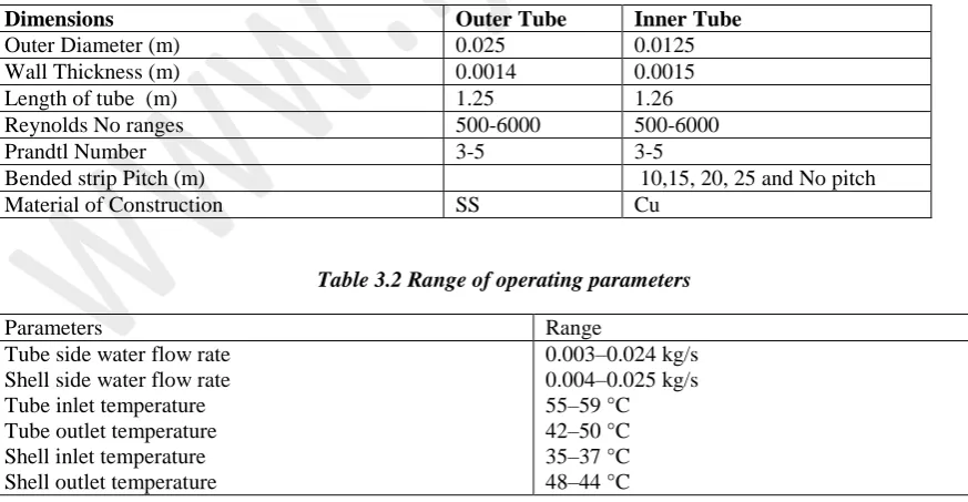
Table No 3.1 Dimensions of Double heat exchanger
Dimensions Outer Tube Inner Tube
Outer Diameter (m) 0.025 0.0125
Wall Thickness (m) 0.0014 0.0015
Length of tube (m) 1.25 1.26
Reynolds No ranges 500-6000 500-6000
Prandtl Number 3-5 3-5
Bended strip Pitch (m) 10,15, 20, 25 and No pitch
Material of Construction SS Cu
Table 3.2 Range of operating parameters
Parameters Range
Tube side water flow rate Shell side water flow rate Tube inlet temperature Tube outlet temperature Shell inlet temperature Shell outlet temperature
Volume 01, No.4, April 2015
P
age
4
A schematic diagram of the experimental apparatus is shown in Fig. 1. It consists of a test section, hot water tank, and cold water tank and data acquisition system. The close-loops of hot and cold water consist of the electric heaters controlled by adjusting the temperature. Water is used as the medium for cooling the hot water. The hot water is adjusted to the desired level and controlled by a temperature controller. The temperatures of the cold and hot water are adjusted to achieve the desired level. The water and tube wall temperatures at the inlet, middle and outlet sections are measured by four K type thermocouples.
Fig.1 experimental setup of double pipe heat exchanger
3.2 Test procedure
Experiments were performed by means of various inlet temperatures and flow rates of hot water entering the test section. In the experiments, the hot water flow rate was increased in inner tube, while the cold water flow rate, and were kept constant. The inlet hot water temperatures were adjusted to achieve the desired level of temperature by using electric heaters controlled by temperature controllers and kept cold water temperature constant. Before any data were recorded, the system was allowed to approach the steady state. The flow rates of the water are controlled by adjusting the valve and measured by two calibrated flow meters by means of a range of 0–0.020 kg/s. The four heat exchangers made by means of different potions of the bended strip inside the inner tube. The inclination angles are 15, 30, 45 and 60° by means of the central axis of the inner tube. For various bended strips we take inlet/outlet temperatures of inner tube and outer tube. Also we will take hydrodynamic performance of the bended strip.
Experimental Procedure is as follows,
a. First filled water in hot water tank up to certain level, and switch ON electric supply to water heater.
b. After 15 minutes thermostatic water heater heat the water up to 60oC. Thermostatic valve maintain the constant 60oC water temperature.
c. Start monoblock to pump hot water from hot water tank and circulate in inner tube. The mass flow rate of hot water is controlled by the flow control valve (FCV) and flow measured by the Rotameter.
Volume 01, No.4, April 2015
P
age
5
e. The test was conducted for counter-flow configuration.
f. Inner tube inlet-outlet and annulus side inlet-outlet temperature measured by temperature indicator in steady state condition of the temperatures.
g. Initially both side mass flow rate varies and taken the observations.
h. For first observation, keep tube side mass flow rate is 15 LPH and Shell side mass flow rate maintained 30 LPH. Likewise vary the tube side mass flow rate and keep shell side mass flow rates is constant. Take inlet-outlet temperatures, pressure drop (mercury difference) and mass flow rates in observation table. i. For next observation, likewise vary the tube side mass flow rate and keep
annulus side mass flow rate is constant. Take inlet-outlet temperatures, mass flow rates and head loss due to friction in observation table. This procedure is continuous for all readings.
j. Hot water outlet again circulates to hot water tank, so that water heater conserves the energy.
k. Next, change heat exchanger, repeat it above procedure for various mass flow rates, and take observations.
3.3 Calculation of tube side heat transfer coefficients
In present investigation, the heat transfer coefficient was determined based on the measured temperature data. The operating parameter range is given in Table 1,
Tube Side Heat transfer
Q=m_t Cp_t (T_hi-T_ho) (1)
Shell Side Heat Transfer
Q=m_s Cp_s (T_co-T_ci) (2)
The physical properties of taken on average temperature
T_m=(T_in+T_out)/2 (3)
The heat transfer coefficient was calculated by means of,
U_o=Q/(A_o ∆T_LMTD ) (4)
The overall heat transfer surface area was determined based on the tube diameter and developed area of tube diameter,A_total=πLd_o is the total convective area of the tube (πLd ) constant for various geometries of inserted bended strips heat exchanger.
A(total convective area )=πLd_o=0.01 mm^2
LMTD is the log mean temperature difference, based on the inlet temperature difference∆T_1, and outlet temperature difference ∆T_2[18, 19],
"LMTD=" ("(" 〖"∆T" 〗_"2" "-" 〖"∆T" 〗_"1" ")" )/("In(" 〖"∆T" 〗_"2" "/" 〖"∆T"
Volume 01, No.4, April 2015
P
age
6
The flow rate in shell side was varying by means of combination to tube side flow rate. The overall heat transfer coefficient can be related to the inner and outer heat transfer coefficient from following equation [4, 5],
1/U_0 =A_o/(A_i h_i )+(A_0 In(d_o/d_i))/2πKL+1/h_o (6)
Where, di and do are inner and outer diameters of the tube respectively. k is thermal conductivity of wall material and L, length of tube (stretch length) of heat exchanger. After calculating overall heat transfer coefficient, only unknown variables are hi and ho convective heat transfer coefficient inner and outer side respectively, by keeping mass flow rate in annulus side is constant and tube side mass flow rate varying.
h_i=CV_i^n (7)
Where Vi are the tube side fluid velocity m/sec. Substituting Equation 4.7 into Equation 4.6, the values for the constant, C, and the exponent, n, were determined through curve fitting. The inner heat transfer could be calculated for both circular and square coil by using Wilson plot method. This procedure is repeated for tube side and annulus side for each mass flow rate on both helical coils
Result and Discussion
The results obtained from the experimental investigation of heat exchanger operated at various operating conditions are studied in detail and presented.
4.1 Thermal Performance
The thermal performance of the double pipe heat exchanger is evaluated in heat transfer rate, overall heat transfer coefficients and Nusselt numbers. The tube side flow rate is varied from the 0.008 kg/s to 0.023 Kg/s, same time annulus side flow rate is maintained constant. The test is conducted for only the counter flow configuration. For each strip geometries, five annulus side flow rates taken i.e. 30, 60, 90, 120, and 150 LPH.
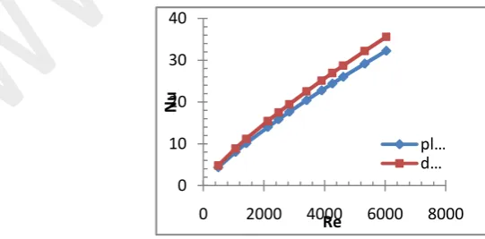
The nusselt number of the plain tube is matches by means of the Detus Bolter equation. The experimental nusselt number of the plain tube is closely matches by means of the available literature. Detus Bolter equation is refered from the lierature and compared the the present data and it found 9% variation shown in figure 2.
Fig. 2 Comparison of the plain tube Nusselt number and Detus Bolter equation 0
10 20 30 40
0 2000 4000 6000 8000
Nu
Re
Volume 01, No.4, April 2015
P
age
7
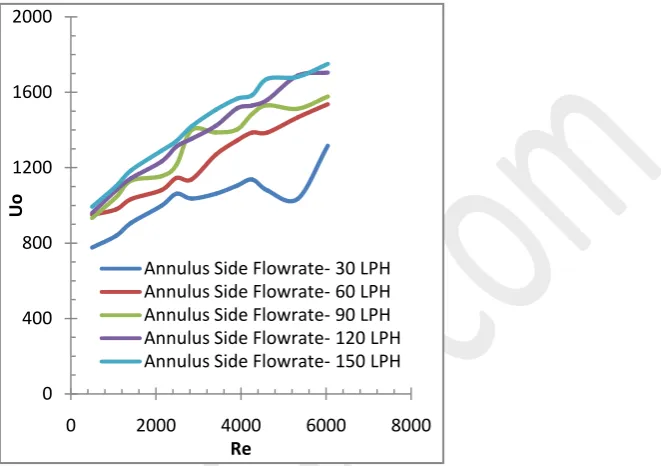
Figure 3 shows the overall heat transfer coefficients changes by means of the tube side hot water flow rate. The convective heat transfer area is constent for all the insrts geometries. In presents study found that the overall heat transfer coeeficient increases by means of increase in the tube side flow rate.
Fig. 3 Variation of overall heat transfer coefficient by means of Reynolds Number for 10mm pitch
Fig. 4 Variation of heat transfer rate by means of Reynolds Number for 10mm pitch
The overall heat transfer coefficient variation by means of respect to the Reynolds number is presented in the figure 4. Heat transfer rate and heat duty also increasing by means of reducing the pitch length. The inserted strip manufactured in the workshop and maintained the uniform pitch throughout the strip. From the one end inserts the strip and condcted the experiment on the various geometries.
0 400 800 1200 1600 2000
0 2000 4000 6000 8000
Uo
Re
Annulus Side Flowrate- 30 LPH Annulus Side Flowrate- 60 LPH Annulus Side Flowrate- 90 LPH Annulus Side Flowrate- 120 LPH Annulus Side Flowrate- 150 LPH
0 400 800 1200 1600 2000
0 2000 4000 6000 8000
Qavg
.
Re
Volume 01, No.4, April 2015
P
age
8
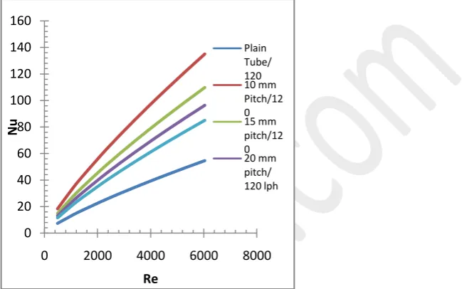
It is found that, the value of Nussult number is maximum for 10 mm pitch per 120 LPH by means of increase in Reynold number. The value of Nussult Number is minimum for Plain Tube . In experimental results shows that, as increases the flow obstruction, its affect on the flow pattern. The flow obstacles generate turbulence inside the inner tube. The turbulence plays important role in the heat transfer enhancement. This is a one of the passive heat transfer technique.
Fig. 5 Variation of inner Nusselt Number by means of Reynolds Number for 120 LPH constant annulus flow rate
Fig. 6 Variation of inner Nusselt Number by means of Reynolds Number for 90 LPH constant annulus flow rate
Figure 5 and 6 presents the Nusselt number variation for the annulus side flow rate i.e. 120 and 90 LPH respectively. The test procedure is same for the all the five annulus side flow rates. Change the bended strip from the other end of the inner tube of the heat exchanger.
0 20 40 60 80 100 120 140 160
0 2000 4000 6000 8000
Nu
Re
Plain Tube/ 120 10 mm Pitch/12 0 15 mm pitch/12 0 20 mm pitch/ 120 lph
0 20 40 60 80 100 120 140
0 2000 4000 6000 8000
Nu
Re
Volume 01, No.4, April 2015
P
age
9
Tube side Reynolds number is varied from the 400 to 7000 and operating hot and cold water temperature is ranges from the 500C to 610C and 250C to 300C respectively. The tube side flow rate is varied by using flow control valve. The Rotameter is used to measure the tube side flow rate and annulus side flow rate.
4.2 Hydrodynamic Performance
The tube side friction factor can be calculated by using the formula,
f= (∆Pd_h)/(2ρv^2 L) (5.1)
Where, dh is the hydraulic diameter in mm, L, length of heat exchanger in mm, v, velocity of the flowing fluid. As changes the geometry of the strip it directly affect on the hydraulic diameter because the volume of material required is more for the 10 mm pitch strip and volume of material required is less for the 25 mm pitch strip.
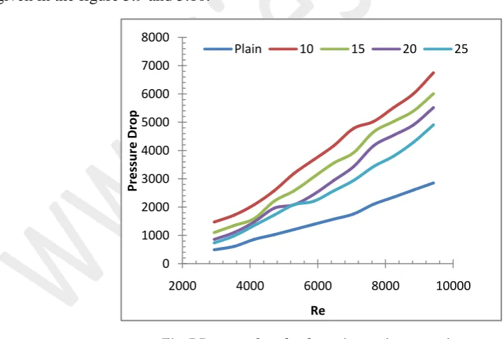
For measurement of the pressure drop U tube manometer is used having the range 150-0-150 mm. The mercury is an media used in the U tube manometer to measure the height of mercury across the heat exchanger. Pressure drop and friction factor is calculated for the various strips geometries, for various mass flow rates. Pressure drop is increases by means of increase in the velocity of the flow. The pressure drop reduces by means of increasing strip pitch and very less pressure drop found in the plain tube. The height and length of the inserted strip is same. The effect of bended strip on the pressure drop and friction factor is given in the figure 5.9 and 5.10.
Fig. 7 Pressure drop for the various strip geometries 0
1000 2000 3000 4000 5000 6000 7000 8000
2000 4000 6000 8000 10000
Pr
e
ssur
e
D
ro
p
Re
Volume 01, No.4, April 2015
P
age
10
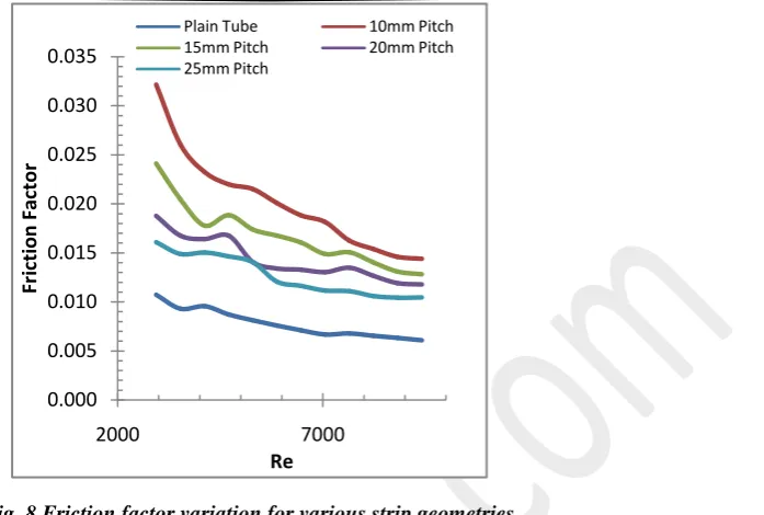
Fig. 8 Friction factor variation for various strip geometries
Pressure drop of the plain tube is less as compared to the other inserted geometries. The plain tube has less obstraction to flow pattern and less turbulence are occurred hence this effect on the heat transfer performance. In tube-in tube heat exchanger various patterns and geometries are inserted for the enhancing heat transfer rate but same time its affect on the pressure drop. Figure 7 and 8 presented the variation of the pressure drop and friction factor by means of change in inner tube side mass flow rate.
CONCLUSION
Experimental study of tube in tube pipe heat exchanger was performed using various bended strip patterns. The mass flow rates in inner tube and in the annulus were both varied. Single-phase water-to-water heat transfer study performed and tested for counter flow configuration. The heat transfer rates in 10 mm pitch were higher than other bended strip. As increases the strip pitch, reduces the heat transfer rate. In present study found that, very low overall heat transfer in plain tube, tube side heat transfer rate progressively increases by means of decreasing inserted strip pitch. In hydrodynamic analysis large pressure drop for the minimum pitch i.e. 10mm and very less pressure drop found in the plain tube. In results, various bended strip patterns compared by means of each other for various operating parameters like heat transfer rate, overall heat transfer coefficients, LMTD and Nusselt number by means of varying tube side hot water flow rates. The friction factor is on higher side for the minimum pitch of bended strip.
REFERENCES
i. Ru Yang, Fan Pin Chiang, “An experimental heat transfer study for periodically varying-curvature curved-pipe”, International Journal of Heat and Mass Transfer, 45 (2002), pp. 3199–3204.
ii. N. Sahiti, F. Krasniqi, Xh. Fejzullahu, J. Bunjaku, A. Muriqi, “Entropy generation minimization of a double-pipe pin fin heat exchanger”, Applied Thermal Engineering, 28, (2008), pp. 2337–2344.
0.000 0.005 0.010 0.015 0.020 0.025 0.030 0.035
2000 7000
Fr
ic
tion
Fact
o
r
Re
Volume 01, No.4, April 2015
P
age
11
iii. Mansoor Siddique, Majed Alhazmy, “Experimental study of turbulent single-phase flow and heat transfer inside a micro-finned tube”, international journal of
iv. Refrigeration, 31, (2008), pp. 234-341.
v. Li Zhang, Wenjuan Du, Jianhua Wub, Yaxia Li, Yanwei Xing, “Fluid flow characteristics for shell side of double-pipe heat exchanger by means of helical fins and pin fins” Experimental Thermal and Fluid Science, 36, (2012), pp 30–43.
vi. Pongjet Promvonge, Somsak Pethkool, Monsak Pimsarn, Chinaruk Thianpong ,“Heat transfer augmentation in a helical-ribbed tube by means of double twisted tape inserts”, International Communications in Heat and Mass Transfer, 39, (2012), pp 953–959.
vii. Chii-Dong Ho, Ho-Ming Yeh, Wen-Yi Yang, “Improvement in performance on laminar counter-flow concentric circular heat exchangers by means of external refluxes” International Journal of Heat and Mass Transfer, 45, (2002), pp. 3559–3569.
viii. Z. Iqbal ⇑, K.S. Syed, M. Ishaq, “Optimal convective heat transfer in double pipe by means of parabolic fins”, International Journal of Heat and Mass Transfer, 54, (2011), pp 5415–5426.
ix. Prabhata K. Swamee, Nitin Aggarwal, Vijay Aggarwal , “Optimum design of double pipe heat exchanger” International Journal of Heat and Mass Transfer 51 (2008) 2260–2266. x. Smith Eiamsa-ard, Somsak Pethkool, Chinaruk Thianpong b, Pongjet Promvonge