F´ed´eration Denis Poisson (Orl´eans-Tours) et E. Tr´elat (UPMC), Editors
ITERATIVE RECONSTRUCTION METHODS FOR WAVE EQUATIONS
S´
ebastien Marinesque
1Abstract. Some new iterative techniques are defined to solve reversible inverse problems and a com-mon formulation is explained. Numerical improvements are suggested and tests validate the methods.
R´esum´e. Nous d´efinissons des techniques it´eratives in´edites pour la r´esolution de probl`emes inverses r´eversibles et en fournissons une formulation commune. Apr`es avoir sugg´er´e des am´eliorations pour leur impl´ementation, des exp´erimentations sont pr´esent´ees qui valident ces m´ethodes.
Introduction
The classical ThermoAcoustic Tomography (TAT) problem formulates as follows. Consider an object f0 contained in an open set Ω ofRn which emits an acoustic pressure wave att= 0, considered as a Dirac pulse. This wave is modeled as a solution of:
Lp= 0 in (0, T)×Ω, p(0) =f0,
∂tp(0) = 0,
(1)
where L is an operator modeling an acoustic wave phenomenon. Then this pressure wave is observed (e.g. thanks to piezoelectric sensors) and a set of observations is obtained from the solutionp. That can be expressed thanks to an observation operator C mapping a solution p to observations Cp. The inverse TAT problem consists in developing and studying methods to reconstructf0 fromCp and to define situations in which this reconstruction is possible. In the three past decades many techniques have been developed, offering effectual results (see works from authors of [1], [5] [11], [13], [16] among others).
The new techniques we propose in section 1 rely on the following ideas, influenced by [2]: if the system we consider is reversible in time, then the initial state to reconstruct can be seen, backward in time, as a state to reach, so that usual control and filtering techniques can be used to solve this inverse problem. For this purpose, we first used the Back and Forth Nudging algorithm (see [2]) in [4]. With filtering techniques, as the Kalman filter defined in [7] and one of its reduced rank formulations, the SEEK filter (cf. [12]), we introduce now possible improvements of this method (in subsection 2.2) and test them (in subsection 2.3). In subsection 1.3, we explain too a common way to formulate and study these iterative reconstruction techniques.
Of course, many assumptions are necessary to obtain a favorable observation situation: the way the wave propagates, depending on the media and on the kind of the wave, the final time and the number, size and position of the sensors command the information contained in the data (see e.g. [9], [10] and the references therein). Moreover, even if the continuous problem is well set, numerical issues still put up some resistance, as considering noisy data, algorithmic complexity or apparition of spurious high-frequency oscillations during
1 Universit´e Paul Sabatier, Institut de Math´ematiques de Toulouse, 118 route de Narbonne, F-31062 Toulouse Cedex
c
EDP Sciences, SMAI 2012
numerical implementations (the paper [18] surveys this point). We deal here with this issue, as done in [14]: we introduce an artificial attenuation term that not only yields a regularization of the solution but corrects degenerated observation configurations for which filtering techniques are not helpful.
1.
Iterative stabilization and filtering for wave equations
This section is devoted to main results about stabilization of the wave equation and Kalman-Bucy filter. Then we define iterative stabilizing methods.
1.1.
Observation and stabilization of the wave equation
We assume that L = ∂tt−∆ is the D’Alembert operator. If necessary, we can suppose that f0 = 0 and consider the stabilization problem for the initial value problem related toLinstead of the inverse TAT problem. Similar considerations are also valid for linear variable speed (reversible) wave equations.
Define p =
p p′
, for any p ∈ C0((0, T);H1 0)∩ C
1((0, T);L2), and A =
0 I
∆ 0
on H = H1 0 ×L
2,
thenD(A) = (H1
0∩H2)×H01and equation (1) writes:
p′=Ap,
p(0) =p0= (f0 0)T,
(2)
for which we consider usual weak, classical or mild solutions, according to the regularity of the initial state. The observations are defined in a Hilbert space U. It is convenient, when working with wave equations, to consider the time derivative of the observations, so that we assume that C ∈ L(L2, U) and use equally Cp′ or Cp. In the practice of TAT, we only get observations frompand use its time derivative when needed.
Concerning stabilizability and controllability of wave equations, we have the fundamental criterion:
Definition 1.1. Theobservation inequality is satisfied if there existsT, M >0 such that:
Z T
0 kCp′
k2Udt≥Mkp0k
2
H, (3)
for allp0∈H, wherepis the solution of (1) with initial datap0. ScalarM is calledobservability constant. Indeed, in [10], one finds the following result:
Proposition 1.2. The three following propositions are equivalent: (i) The observation inequality (3)is satisfied.
(ii) For every positive-definite self-adjoint operator T ∈L(U), the operator A−C⋆T C generates an
expo-nentially stable C0-semigroup on H. (iii) The system (A, C⋆)is exactly controllable.
Many geometrical interpretations to the observation inequality have been presented, mostly known as Geo-metric Optics Condition (GOC from [3]). In particular, these results explain this heuristic situation: whenCp′=
1ωp′, whereω is an open subset of Ω, then enough energy fromp0 has to pass throughω to get enough infor-mation to reconstruct p0. It depends on many parameters such as the position of the sensors, the speed map of the wave equation, the final time T, etc.
In this context, we introduce a first reconstruction method, the Kalman-Bucy filter.
1.2.
The Kalman-Bucy filter
Assume that the true state solves the linear differential equation xt′
=Mxt
+ν and the theoretical model is governed byxf′
=Mxf
. Given datayo, we denote the observation error byε, so asε=yo−Cxt
. Errorsε andν are null mean white Gaussian noise processes and their respective covariance matrices areQandR. Definition 1.3. Given xf
(0) and Pf
(0), the Kalman-Bucy filter consists in the two following differential equations, one to estimate the statexand one for the covariance matrixP, of a differential Riccati type:
x′ = Mx+PCTR−1(yo−Cx),
P′ = MP+PMT+Q
−PCTR−1CPT, and the Kalman gainKis given byK=PCTR−1.
Let us explain some links between subsections 1.1 and 1.2. In the filters formulations, the feedback is realized thanks to an operator written P C⋆T C as feedbacks write C⋆T C and P = Id
H in subsection 1.1. Thus one can consider here thatP weights the feedback in comparison to the model. See [17] for some results similar to Proposition 1.2 about feedbacksP C⋆T C.
We are studying different ways to define the stabilizing operatorP, first with the nudging operatorP C⋆T C=
kC⋆C, wherek >0, that is in the framework of Proposition 1.2, then with filters. It leads to the following back and forth reconstruction algorithms.
1.3.
Iterative initial data reconstruction methods for inverse problems
We get benefits from the reversibility of the wave equations, go back in time and use data again during a backward evolution, fromt=T to t= 0, to deduce an approximation off0. Such an idea has lead D. Auroux and J. Blum to define the Back and Forth Nudging algorithm in [2], then D. Auroux and E. Cosme improved it with the Back and Forth SEEK (from private communication, see below for a description of the BF-SEEK). These techniques can be formulated for any sequences of positive operators (Pkf),(Tkf),(Pb
k),(Tkb) as follows:
Definition 1.4. Given a set of observations Cpo and a rough estimate p
0, define pb0(0) = p0. An iterative reconstruction method consists in iterating a back and forth process. The forward solution is given by:
∂ttpfk= ∆p f k−P
f kC⋆T
f kC(p
f
k−po) in (0, T)×Ω, (4)
with initial datapfk(0) =p f
k−1(0) andp
f
k′(0) = 0 and the backward solution solves:
∂ttpbk= ∆pbk+PkbC⋆TkbC(pbk−po) in (0, T)×Ω, (5)
withfinal datapb
k(T) =p f
k(T) andpbk′(T) =p f
k′(T). The process is iterated fork≥1.
Concerning P C⋆T C, it is left implicit that time or space derivatives of (pf
k −po) and (pbk −po) can be considered. The sign precedingPb
kC⋆TkbC(pbk−po) changes for convenience of notation as one can notice that, whenT contains a first-order time derivative, then the backward equation (5) writes forward:
∂ttpbk= ∆pbk−PkbC⋆TkbC(pbk−po),
thanks to the variable substitutiont7→T−t. Finally, the correcting term still helps to stabilize the system. Note that unlike many usual methods, the model is considered here as a weak constraint, which can be useful since it may not be well known (e.g. refer to [6] about simulation of inhomogeneous acoustic speed model and relative issues in TAT).
Finally, this kind of algorithms yields successive estimates (pb
2.
Numerical experiments
2.1.
Discretization and numerical considerations
Consider the 1-D domain Ω = (−1/2,1/2) and (0, T) = (0,1) both uniformly gridded with stepsδx= 1/100 and δt= 1/200. We deal with the classical finite difference time domain theta-scheme (θ-FDTD) to simulate the wave equation. Sensors are located periodically everyδdatagrid points from the first one.
Upper discussion about observability, stabilizability and controllability have their matching in this situation: a discrete observation condition occur, similar to (3), which is equivalent too to the discrete stabilizability of the system (we omit details, see [18] and the reference therein whenθ= 0). In order to compensate for possibly damaged observation conditions, due either to sensors configuration or to noise, we carry out the solution suggested in [14], adding an artificial viscous heating attenuation term in the θ-FDTD, that leads to:
pn+1−2pn+pn−1
δt2 = ∆
θ
δx(pn−1, pn, pn+1) +ε∆δxpn−pn−1
δt ±P C
⋆T C
pn−1−pon−1
pn−pon
,
where ∆θ
δx(pn−1, pn, pn+1) =θ∆δxpn−1+ (1−2θ)∆δxpn+θ∆δxpn+1,θ= 0.25,ε= 0 orε= (δx)α,α∈(1,2), and±stands to express both forward and backward implementations.
The term pn−1−pon−1 pn−pon
T
allows us to consider derivatives of the correcting term in the feedbacks.
2.2.
From Kalman to SEEK filter
Only main results about the Kalman filter are given and we describe then how to derive the SEEK filter from it (as in [15]). These algorithms divide into two steps, a forecast one and an analysis one, in which are taken account the observations to correct the forecast, and two different kinds of parameters are considered, first the states (xf
andxa
), then the relative error covariance matrices (Pf
andPa
) or their square root (Sf
andSa
). Definitions of the Kalman and SEEK filters are explained respectively on left and right columns below. Definition 2.1. Givenxf
0,P
f
0andS
f
0=P
f1/2
0 , one iterates:
Kalman Filter (KF) SEEK Filter
Analysis step Analysis step
Kn=Pfn−1+CTR−1C
−1
CTR−1, K
n=Sfn
Ir+ (CSfn)TR−1(CS
f
n)
−1
(CSf
n)TR−1,
xa
n=x
f
−KnCxfn−yon
, xa
n=x
f
n−KnCxfn−yon
,
Pa
n = [In−KnC]Pfn, S
a
n=S
f
n
Ir+ (CSfn)TR−1(CS
f
n)
−1/2 ,
Forecast step Forecast step
xf
n+1=Mx
a
n, x
f
n+1=Mx
a
i,
Pf
n+1=MP
a
nMT+Q. S
f
n+1=MS
a
n.
whereIk is thek×kidentity matrix (in the discrete state space ifk=nand in the reduced rank space ifk=r) and Kn is the Kalman gain, minimizing the trace of the error covariance onx
a
i, or the reduced rank Kalman gain in SEEK.
Theoretically, one hasPf
n=S
f
nS
fT
n +Qin SEEK, but sinceQis not well known, we defineP
f
n= (1+γ)S
f
nS
fT n , whereγ∈(0,1), which avoids an additional decomposition in SEEK. It is set similarly in KF.
In KF, if the state space has a range ofn, the forecast step necessitates 2nmodel evolution steps to get the forecast error covariance matrix from the analysis error covariance matrix, such that a less optimal gain may be considered to reduce calculation cost. This is the purpose of the SEEK to yield such a gain by considering a reduced rank gain more simple to obtain. Since the error covariance matrices are symmetric and positive-definite, Pham et al. [12] suggested to consider the following decomposition: ifP is a symmetric positive-definiten×n
2.3.
Results
Four methods are compared: Time Reversal (TR), Back and Forth Nudging (BFN), Back and Forth SEEK (BF-SEEK) and Kalman Filter (KF). Let us set R = 0.3I, γ = 0.01 for both BF-SEEK and KF, and the reduced rankr= 120, which is reduced when Rank
I+ (CSf
i)TR−1(CS
f
i)
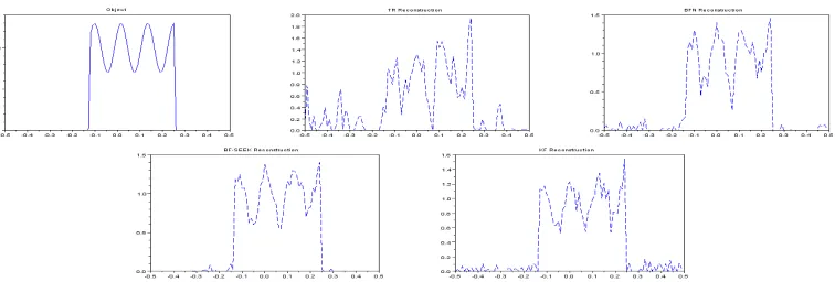
< r. An additive white Gaussian noise of levelν is added to the data when said. The nudging gain is set to 0.9δtfor implementation limitations. Table 1 and Fig. 1 and 2 show RMS errors and some relative reconstructions obtained in various situations. The object to reconstruct is shown on the upper left part of figure 1 then, to the right, one sees TR and BFN reconstructions, followed by BF-SEEK and KF reconstructions.
Settings TR BFN BF-SEEK SEEK KF
δdata= 10 5.4 0.5 (100) 0.6 (3) 5.8 6
δdata= 10, ν= 30% 38.8 16.3 (5) 10.3 (2) 12.4 15.7
δdata= 99 8.3 2.6 (100) 6.3 (1) 15.9 44.2
δdata= 99, ν= 30% 14.1 10.8 (14) 19.9 (1) 23.7 46.4
δdata= 99, ν= 30%, α= 2 9.8 20.7 (8) 12.2 (1) 20.1 42
δdata>99 51.1 20.7(7) 31.8 if83α.3 (3)= 1.8 (3) 92.7 95
Table 1. RMS errors and number of iterations to converge (in brackets) for 10 (δdata= 10), 2 (δdata = 99) and 1 (δdata>99) sensor(s), noisy (ν = 30%) or noiseless data, with or without the numerical attenuationδxα.
Figure 1. Object to reconstruct and reconstructions by TR, BFN, BF-SEEK and KF forδdata= 10 andν= 30%.
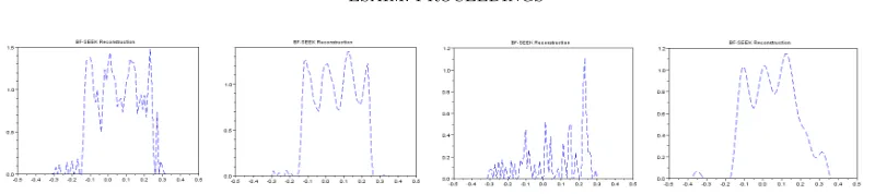
As KF reacts quite well to noise addition, it shows much more sensitivity to the number of sensors and easily fails. SEEK and BF-SEEK offer obvious improvements for both calculation cost and reconstruction error (Fig. 1). When 2 sensors are left, one can observe possible interesting effects of the attenuation term against noise with TR and BF-SEEK. Nevertheless, it may damage the reconstruction (with BFN). When only 1 sensor is left, only BFN and BF-SEEK are robust enough to yield a good approximation of the object, but BF-SEEK needs to be corrected with the attenuation to keep stable (Fig. 2).
All in all, interests in Back and Forth techniques are justified since BF-SEEK improves significantly the SEEK filter in any situation we test.
3.
Conclusions
Figure 2. BF-SEEK reconstructions. Caseδdata= 99 andν = 30%: α= 0 (a) andα= 2 (b). Caseδdata>99: α= 0 (c) andα= 1.8 (d).
introduced may offer an alternative to usual inverse methods for TAT problem. In applications, knowledge about the quality of the sensors, the background and the model approximations can be used by filters, but in this case they need to be precisely tuned.
The use of an artificial attenuation is motivated by good results, and allows one to consider lossy medium in back and forth implementations when the physical loss does not exceed the numerical attenuation.
When space dimension increases, we first face an excessive calculation cost (one BF-SEEK iteration with rank 60 equals almost one thousand BFN in computation time). So one would get interested in hybrid methods, e.g. getting first estimates with TR and BFN and then reconstructing the solution with filters. A solution is offered by Perfectly Matched Layers to reduce the space domain of calculation and for which a first order discrete scheme formulation is necessary for the filters.
References
[1] M. Agranovsky, P. Kuchment and L. Kunyansky, 2009,On reconstruction formulas and algorithms for the thermoacoustic and photoacoustic tomography, Ch. 8inL. H. Wang (Editor) ”Photoacoustic imaging and spectroscopy”, CRC Press, pp. 89-101. [2] D. Auroux and J. Blum, 2005, Back and Forth Nudging algorithm for data assimilation problems, C. R. Acad. Sci. Paris,
Ser. I, 340, pp. 873-878.
[3] C. Bardos, G. Lebeau and J. Rauch, 1992,Sharp sufficient conditions for the observation, control and stabilization of waves from the boundary, SIAM J. Control Optim., Vol. 30, pp. 1024-1065.
[4] X. Bonnefond and S. Marinesque, 2010,Application of a nudging technique for thermoacoustic tomography, Preprint. [5] D. Finch, S. Patch and Rakesh, 2004, Determining a function from its mean values over a family of spheres, SIAM
J. Math. Anal., Vol. 35 (5), pp. 1213-1240.
[6] X. Jin and L. V. Wang, 2006, Thermoacoustic tomography with correction for acoustic speed variations, Med. Biol., Vol. 51, pp. 6437-6448.
[7] R. E. Kalman, 1960,A new approach to linear filtering and prediction problems, Transactions of the ASME - Journal of Basic Engineering, Vol. 82, pp. 35-45.
[8] R. E. Kalman and R. S. Bucy, 1961,New result in linear filtering and production theory, J. Basic Eng., Maroh., pp. 95-108. [9] P. Kuchment and L. Kunyansky, 2010, Mathematics of thermoacoustic tomography, Chapter 19 in Vol. 2 of ”Handbook of
Mathematical Methods in Imaging”, pp. 817-866, Springer Verlag, arXiv: 0912.2022v1.
[10] K. Liu, Locally distributed control and damping for the conservative systems, SIAM J. Control Optim., 1997, Vol. 35 (5), pp. 1574-1590.
[11] G. Paltauf, R. Nuster, M. Haltmeier and P. Burgholzer, 2007,Photoacoustic tomography using a Mach-Zehnder interferometer as acoustic line detector, Appl. Opt., Vol. 46, pp. 3352-3358.
[12] D. T. Pham, J. Verron and M. C. Roubaud, 1998, A singular evolutive extended Kalman filter for data assimilation in oceanography, J. Marine Sys., Vol. 16, pp. 323-340.
[13] J. Qian, P. Stefanov, G. Uhlmann and H. Zhao, 2010, A new numerical algorithm for thermoacoustic and photoacoustic tomography with variable sound speed, arxiv.org/abs/1101.3729.
[14] K. Ramdani, T. Takahashi and M. Tucsnak, 2007,Uniformly exponentially stable approximations for a class of second order evolution equations, Application to LQR problems, ESAIM: COCV, Vol. 13 (3), pp. 503-527.
[15] D. Rozier, F. Birol, E. Cosme, P. Brasseur, J. M. Brankart and J. Verron, 2007, A reduced-order Kalman filter for data assimilation in physical oceanography, SIAM Rev., Vol. 49 (3), pp. 449-465.
[16] M. Xu and L.V. Wang, 2006,Photoacoustic imaging in biomedecine, Rev. Sci. Instrum., Vol. 77 (4), 041101.
[17] J. Zabczyk, 1976,Remarks on the algebraic Riccati equation in Hilbert space, Appl. Math. Optim., Vol. 2 (3), pp. 251-258. [18] E. Zuazua, 2005, Propagation, observation, and control of waves approximated by finite difference methods, SIAM Rev.,