Optimization of a Wideband Tapped-Delay Line Array
Antenna
N. Noori*
Abstract: In this paper, an optimal approach to design wideband Tapped-Delay Line(TDL) array antenna is proposed. This approach lets us control the array angular and frequency response over a wide frequency band. To this end, some design restrictions are defined and a multi-objective optimization problem is constructed by putting the individual restrictions together. The optimal weights of the TDL processor are determined through solving this multi-objective problem. A design example is presented to show performance of the proposed method and compare the array response with those previously published in the literature.
Keywords: Beamforming, Multi-Objective Optimization, Tapped-Delay Line (TDL),
Wideband Array.
1 Introduction1
Array beamforming as a signal processing technique is widely used in wireless communication systems for directional transmission or reception of signals [1-4]. This technique is applied in various areas from medicine to military and communications. In a conventional narrowband beamformer, the array output is formed by multiplying the corresponding signal of each array element by a complex weight [5]. However, the narrowband beamformers with a single constant weight for each array element, are only useful for sinusoidal or narrowband signals and do not work efficiently for wideband signals consist of different frequency components. Thus, a set of frequency dependent weights is necessary to form a wideband beamformer with the same response for different frequencies. A wideband beamforming structure can be achieved by different techniques [6]. An easy way to form such a beamformer is to use a tapped-delay line (TDL) filter on each branch of the array. The TDL arrays are widely used in wideband and ultra wideband communications [7-9]. These structures employ a combination of special and temporal filtering to form a frequency dependent response and allow adjusting the beamformer response as desired over the band of interest.
In TDL arrays, the filter coefficients are determined by solving some constrained beamforming problem [10-12]. In [10], a receiving array which simultaneously
Iranian Journal of Electrical & Electronic Engineering, 2014. Paper first received 7 Oct. 2013 and in revised form 1 Feb. 2014. * The Author is with the Department of Communication Technology, ICT Research Institute (ITRC), Tehran, Iran.
E-mail: [email protected].
minimizes output noise power and satisfies certain robustness and bandwidth criteria is considered. Several broadband beamforming design methods based on the least squares formulation have been proposed in [11]. In [12], authors derive a set of convolution constraints to obtain desired frequency response of the TDL processor. The method of vector space projections is applied in [13] to design a broadband TDL array. This array provides promising angular and frequency response, however, as authors point out, the optimality of the design is not guaranteed.
The optimal designs with respect to some criterions are intensively considered for array antennas. These kinds of design provide the best fit for the required needs. However, to the author's best knowledge, it has not been reported any optimal design for TDL array antenna. In this paper, we propose an approach based on the multi-objective optimization to optimize the design of a wideband TDL array antenna. This approach determines the weights of the TDL processor by taking into account all the design constraints and results in an optimal desired angle and frequency response. The performance of the proposed method is investigated by a design example and the numericalresults are compared with those reported in [13].
The organization of this paper is as follows. In Section 2, the structure of the TDL array antenna is reviewed. In Section 3, a multi-objective optimization problem is defined to design the array. Some numerical simulation results including a design example are presented in Section 4 and finally Section 5 concludes the paper.
2 Wideband TDL Array Antenna
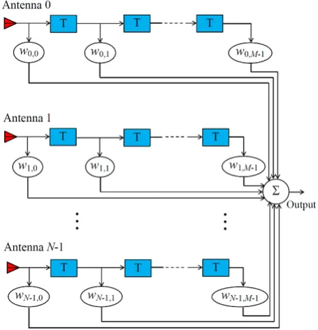
A wideband TDL array antenna forms a finite impulse response (FIR) filter that can be constrained to provide the desired frequency response for the broadband beamformer. This frequency dependent response provides a temporal filtering to compensate the phase difference for different frequency components [7]. In this structure, the propagating wave is received by N omni-directional antenna elements. As shown in Fig. 1, each antenna is connected to M delay lines with the delay of T between adjacent taps. The output of this beamformer which samples the propagating wave in both space and time, can be written as [14]:
1 1
, 0 0
( ) N M n m n( ), n m
y t − − w x t mT
= =
=
∑ ∑
−
(1)
where w is a complex beamformer weight at the n m, mth tap position of the nth delay line and ( )x tn is the input signal to the
n
th antenna element. According to Eq. (1), the received signals on the TDL processor are multiplied by a set of complex weights before summing to produce the array output.In a uniform one-dimensional linear array with inter-element spacing d , the delay time exists between the signal received at thenth antenna element and the signal received at the reference element (with n=0), can be expressed as:
sin ,
n
d n
c
=
τ θ (2)
where c is the propagation speed and θ is the incoming signal angle. To avoid aliasing,dmust be less than
min 2
λ , where λmin is the wavelength of the highest frequency component of the input signal. In a narrowband beamformer, the main beam can be steered to a desired direction by adding phase shift to the array elements. The relationship between the steered response and the original one is simple for a half wavelength spaced linear array. While, adding phase shift for wideband beamformers can steer the main beam to a specific direction, but in general there is not a one-to-one correspondence between the original beam response and the steered one [6].
Now, for an impinging signal 0( ) j t
x t =eω , the output
signal is [6]. 1 1
( ) ,
0 0
( ) n ( , ),
N M
j mT
j t j t
n m n m
y t e − − w e− + e H
= =
= ω
∑ ∑
ω τ = ω × θ ω (3)where H( , )θ ω is the angle and frequency dependent response of the beamformer and is expressed by:
1 1 sin
, 0 0
( , ) .
d
N M jn
jm T c n m
n m
H − − w e− e−
= =
=
∑ ∑
ω ω θθ ω
(4)
Assuming the normalized frequency Ω=ωT and if
μ=(d/cT), Eq. (4) can be re-written as:
Fig. 1 General structure of a wideband TDL array antenna.
1 1
sin ,
0 0
( , ) N M jm jn .
n m n m
H − − w e− Ω − Ωe
= =
Ω =
∑ ∑
μ θθ (5)
For simplicity, we assume that μ=1 or d =cT. In wideband pattern synthesis, the weights of the TDL processor should be determined so that all design constraints in the angular and frequency domains are met. These constraints are defined to obtain a desired frequency response in a particular direction while simultaneously cancel the unwanted signals impinging on the array from other directions. Different methods can be utilized to compute the weights of the beamformer and meet the design constraints. In the next section, a multi-objective based optimization problem is proposed to optimize the solution of the problem. In this approach, the array weights are obtained such that the best fit to the desired response is provided.
3 Optimal Design of Wideband Beamformer A multi-objective optimization problem is concerned with the minimization of a vector of objectives that may be the subject of a number of constraints or bounds. The general form of this problem is defined as follows:
min ( )
n X∈ℜ F X
subject to :
( ) 0, 1,..., , p
f X ≤ p= P
( ) 0, 1,..., , q
h X = q= Q (6)
,
l u
X ≤X X≤
where F X( )=
{
F X F X1( ), ( ),..., ( )2 F Xk}
is the vector of objectives.We need to consider all design constraints to formulate the vector of objective functions for our array design problem. First, since a relative flat beamformer response is required in the passband, the passband main-lobe level constraints are defined as follows
:
1: ( , ) MLL, , P BML,
C H θ Ω ≥H ∀θ Ω ∈ ℜ
(7)
2 : ( , ) MLU, , P BML,
C H θ Ω ≤ H ∀θ Ω ∈ ℜ (8)
where HMLL and HMLU are the lower and upper bounds of H( , )θ Ω within the main-lobe region, respectively. Also, ℜPBML is the set of normalized passband frequencies and main-lobe spatial angles. The lower and upper bounds of the beamformer frequency response should be selected as HMLL ≤ HMLU .
Next, the stopband sidelobe level constraint is defined as follows:
3 : ( , ) SLU, , SBSL,
C H θ Ω ≤H ∀θ Ω ∈ ℜ (9)
where HSLU is the upper bound of H( , )θ Ω within the sidelobe region and ℜSBSL is the set of normalized stopband frequencies and sidelobe spatial angles.
The total power constraint, implies the minimum required power level for the beamformer operation, can be expressed as:
1 1 2
4 ,
0 0
:N M n m .
n m
C − − w N M
= =
≥ ×
∑ ∑
(10)Since C3 and C4 are the upper and lower bounds of the radiated power, the beamformer parameters must be selected so that C3∩C4 is not empty.
Finally, the excitation of each antenna element is bounded as follows:
5: n m, max, 0,..., 1; 0,..., 1,
C w <w m= M − n= N− (11)
where, the maximum excitation of each element is specified by wmax
.
The vector of objectives, ( , )F θ Ω ={
F1( , ),θ Ω F2( , ) ,θ Ω F3( , ),θ Ω F4( , )θ Ω}
is defined as follows to handle the above constraints:1
( , )
( , ) max 0, 1 ,
PBML MLL
H
F d d
H ℜ
⎧ ⎛ Ω ⎞⎫
⎪ ⎪
Ω = ⎨ −⎜ − ⎟⎬ Ω
⎪ ⎝ ⎠⎪
⎩ ⎭
∫∫
θθ θ (12)
2
( , )
( , ) max 0, 1 ,
PBML MLU H
F d d
H
ℜ
⎛ Ω ⎞
Ω = ⎜ − ⎟ Ω
⎝ ⎠
∫∫
θθ θ (13)
3
( , )
( , ) max 0, 1 ,
SBSL SLU H
F d d
H
ℜ
⎛ Ω ⎞
Ω = ⎜ − ⎟ Ω
⎝ ⎠
∫∫
θθ θ (14)
1 1 2
4 ,
0 0
1
( , ) max 0, 1 .
N M
n m n m
F w
N M
− −
= =
⎧ ⎛ ⎞⎫
Ω = ⎨ −⎜ × − ⎟⎬
⎝ ⎠
⎩
∑ ∑
⎭θ (15)
Then, the weighted sum strategy is applied to obtain the optimal beamformer weights:
,
4
1
min ( , ) ( , ),
subject to :
n m i i
w F θ Ω =
∑
i= α F θ Ω, max, 0,..., 1; 0,..., 1, n m
w <w m= M− n= N− (16)
where F1 and F2 express the passband main-lobe level constraints, C1 and C2. Also, F3 implies the stopband sidelobe level constraint,C3 and F4 expresses the total power constraint, C4. This approach converts the multi-objective optimization problem into a scalar problem by constructing a weighted sum of all the objectives. In this approach, C1 to C4 are converted to a weighted sum of objectives. Also, C5 is considered as a constraint for defined optimization problem. Note that in Eq. (16),
i
α s are the weight of the objective function Fi. These weights are defined as follows:
1= 2 = 4 =1,
α α α 3 PBML PBML,
SBSL SBSL
Δ ΔΩ
=
Δ ΔΩ
θ α
θ (17)
where ΔθPBML and ΔθSBSL are the total main-lobe and sidelobe angular widths of the beamformer, respectively. Also, ΔΩPBML and ΔΩSBSL are the total passband and stopband frequency widths, respectively. Therefore, α3 is set to the ratio of ℜPBML to ℜSBSL.
4 Numerical Simulations
To investigate performance of the optimal design approach, we compare our results with those of the vector space projections method published in [13]. For this purpose, a TDL beamformer is designed to operate in two frequency ranges 1.6-2.56 GHz and 5.44-6.72 GHz. The main-lobe width is 14˚ and it is centered at 30 . The array parameters are N=31 and M=31 where the inter-element spacing is equal to 0.0187 cmand the time delay is T=6.25 10 s× −11 (or μ =1). The lower and upper bounds of the main-lobe magnitude levels are set in arbitrary units to 450 and 500, respectively, while the sidelobe upper bound magnitude level is set to 35. The maximum excitation of each antenna element is
max 2
w = . It should be noted that the array response is not controlled outside the region specified by
PBML SBSL
ℜ ∪ℜ .
The simulated annealing algorithm is used to find the optimal beamformer weights. The starting point of the algorithm can be any 31×31 vector,w0, where its elements are generated by uniform amplitude and phase distributions on the intervals [0,2] and [0,2π], respectively. The initial temperature for simulated annealing is set to 100 and the algorithm is stopped after 300 iterations. The optimization process is repeated several times to make sure that the algorithm converges to the same solution.
Fig. 2 Beamformer response in the lower passband.
Fig. 3 Beamformer response in the stopband.
Fig. 4 Beamformer response in the upper passband.
The results of the beamformer design are shown in Figs. 2-4. The ratios of the main-lobe to maximum sidelobe level achieved by the optimal design are more than 18 dB and 21 dB in the lower and upper passbands, respectively. These ratios are 14 dB and 16 dB, respectively for vector space projections design [13].
Note that, the response of the optimal beamformer is flat in both passbands. Furthermore, the ripple is less than 2 dB which is equal to the ripple reported for vector space projections design. The resulted frequency response in the stopband is 23 dB down from the main-lobe level in the passbands. This difference is 19 dB for the vector space projections design.
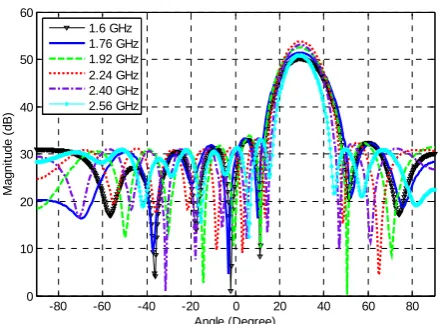
We also investigate performance of the proposed approach for another TDL beamformer with N=20 and M=15 which is designed to operate in the frequency ranges 2.24-2.56 GHz and 5.76-6.4 GHz. In this case, the lower and upper bounds of the main-lobe magnitude levels are set to 195 and 205, respectively. Also the sidelobe upper bound magnitude level is set to 35. The other parameters of this beamformer are the same as the previous one.
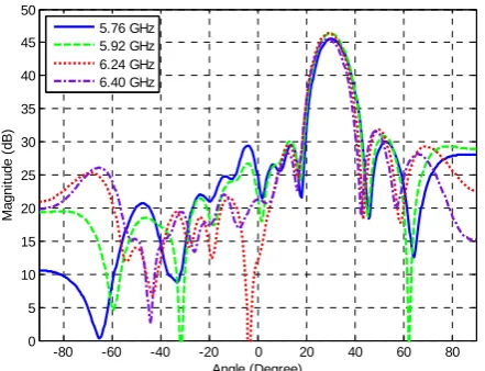
The results of the beamformer design are shown in Figs. 5-7. In this case, the ratios of the main-lobe to maximum sidelobe level are more than 13 dB and 16 dB in the lower and upper passbands, respectively. The response of the beamformer has a ripple is less than 1 dB in the passbands.
Fig. 5 Beamformer response in the lower passband.
Fig. 6 Beamformer response in the stopband.
-80 -60 -40 -20 0 20 40 60 80 0
10 20 30 40 50 60
Angle (Degree)
M
agni
tude (
d
B)
1.6 GHz 1.76 GHz 1.92 GHz 2.24 GHz 2.40 GHz 2.56 GHz
-80 -60 -40 -20 0 20 40 60 80 0
10 20 30 40 50 60
Angle (Degree)
Ma
g
n
it
u
d
e
(
d
B
)
3.36 GHz 3.84 GHz 4.16 GHz 4.64 GHz
-80 -60 -40 -20 0 20 40 60 80 0
10 20 30 40 50 60
Angle (Degree)
M
agni
tu
de (
d
B)
5.44 GHz 5.76 GHz 5.92 GHz 6.24 GHz 6.40 GHz
6.72 GHz -80 -60 -40 -20 0 20 40 60 80
0 5 10 15 20 25 30 35 40 45 50
Angle (Degree)
M
agn
it
u
d
e
(
d
B)
2.24 GHz 2.40 GHz 2.56 GHz
-80 -60 -40 -20 0 20 40 60 80 0
5 10 15 20 25 30 35 40 45 50
Angle (Degree)
M
a
gni
tude
(
d
B
)
3.36 GHz 3.84 GHz 4.16 GHz 4.64 GHz
Fig. 7 Beamformer response in the upper passband.
5 Conclusion
In this paper, the optimal design of the wideband TDL beamformer was presented using a multi-objective optimization problem. The optimal weights of the TDL processor are determined through solving this multi-objective problem. The simulated annealing algorithm was then applied to solve the optimization problem and find the optimal bemformer weights. A comparison between the optimal bemformer responses with those reported for the vector space projections method showed the superiority of our proposed approach over vector space projections. It was shown that in the optimal design, the achieved main-lobe to maximum sidelobe level is at least 4 dB better than the values reported for vector space projections design. Moreover, numerical simulation results showed that in the optimal design, the difference between the passband main-lobe level and stopband frequency response of the beam former is about 4 dB more than the values obtained by vector space projections.
Acknowledgment
This work is supported by ICT Research Institute.
References
[1] S.-J. Yu and J.-H. Lee, “Adaptive array beamforming based on an efficient technique”, IEEE Trans. on Antennas and Propagat., Vol. 44, No. 8, pp. 1094-1101, 1996.
[2] B. Liao and S.-C. Chan, “Adaptive Beamforming for Uniform Linear Arrays with Unknown Mutual Coupling”, IEEE Antennas and Wireless Propagation Letters, Vol. 11, pp. 464-467, 2012. [3] S. Farzaneh and A.-R. Sebak, “An optimum
adaptive single-port microwave beamformer based on array signal vector estimation”, IEEE Trans. on Antennas and Propagat., Vol. 58, No. 3, pp. 738-746, 2010.
[4] J. Montesinos, O. Besson and C. Larue de Tournemine, “Adaptive beamforming for large arrays in satellite communications systems with
dispersed coverage”, IET Communications, Vol. 5, No. 3, pp. 350-361, 2011.
[5] J. Litva, Digital Beamforming in Wireless Communications, Artech House, 1996.
[6] W. Liu and S. Weiss, Wideband Beamforming Concepts and Techniques. Wiley, 2010.
[7] S. Obote, Y. Ichikawa and K. Kagoshima, “A design methodology of a tapped delay line adaptive array antenna”, in Proc. IEEE Antennas and Propagation Society International Symposium, Vol. 4A, pp. 30-33, 2005.
[8] N. Ramli, W. N. Shazwanie, W. M. Zuferi, A. Daud and H. Mohamad, “Pre-FFT tapped delay line adaptive array for STBCOFDM transmission in CR network”, in Proc. IEEE TENCON Spring Conference, pp. 242-246, 2013.
[9] J. R. Adleman, C. L. Lin, B. M. N. Pascoguin, B. Neuner, A. Hening, M. Lasher, E. W. Jacobs and J. S. Rodgers, “Two-layer integrated optical tapped delay line for RF spectrum analysis”, Proc. IEEE Photonics Conf. (IPC), pp. 90-91, 2012. [10] K. M. Ahmed and R. J. Evans, “An adaptive array
processor with robustness and broad-band capabilities”, IEEE Trans. On Antennas and Propagat., Vol. 32, No. 9, pp. 944-950, 1984. [11] S. Doclo and M. Moonen, “Design of broadband
beamformers robust against gain and phase errors in the microphone array characteristics”, IEEE Transactions on Signal Processing, Vol. 51, No. 10, pp. 2511- 2526, 2003.
[12] L. C. Godara and M. R. SayyahJahromi, “Convolution Constraints for Broadband Antenna Arrays”, IEEE Trans. Antennas Propagat., Vol. 55, No. 11, pp. 3146-3154, 2007.
[13] J. Gu, H. Stark and Y. Yongyi, “Design of tapped-delay line antenna array using vector space projections”, IEEE Trans. Antennas Prop., Vol. 53, No. 12, pp. 4178-4182, Dec. 2005. [14] M. Ghavami, L. B. Michael and R. Kohno,
Ultra-Wideband Signals and Systems in Communication Engineering, Wiley, 2004.
Narges Noori received B.Sc., M.Sc. and Ph. D. degrees (with honours) from Iran University of Science and Technology (IUST), Tehran, Iran, all in Electrical Engineering, in 1998, 2000 and 2006, respectively. From June 2004 to April 2005, she was with the RF/Microwave and Photonics Group, University of Waterloo, Waterloo, Ontario, Canada as a visiting scholar. In May 2005, she joined ICT Research Institute (Iran Telecommunication Research Center), Tehran, Iran, where she is now working as a research assistant professor. In 2008, she received the best researcher award from Iran ministry of ICT. She has participated and managed several research projects in radio communication group of ITRC. Her research interests include beamforming and power control in cognitive radio networks, radio propagation modeling, ultra wideband communications and numerical methods in electromagnetics.
-80 -60 -40 -20 0 20 40 60 80 0
5 10 15 20 25 30 35 40 45 50
Angle (Degree)
M
a
gn
it
ud
e
(
d
B)
5.76 GHz 5.92 GHz 6.24 GHz 6.40 GHz